door lock Ram 3500 2018 Owner's Manual
[x] Cancel search | Manufacturer: RAM, Model Year: 2018, Model line: 3500, Model: Ram 3500 2018Pages: 372, PDF Size: 7.1 MB
Page 32 of 372
This feature can be programmed through the
Uconnect system. Refer to “Uconnect Set-
tings” in “Multimedia” in the Owner’s
Manual for further information.
WARNING!
• Persons who are unable to feel pain tothe skin because of advanced age,
chronic illness, diabetes, spinal cord in-
jury, medication, alcohol use, exhaus-
tion, or other physical conditions must
exercise care when using the steering
wheel heater. It may cause burns even at
low temperatures, especially if used for
long periods.
• Do not place anything on the steering
wheel that insulates against heat, such
as a blanket or steering wheel covers of
any type and material. This may cause
the steering wheel heater to overheat.
DRIVER ADJUSTABLE PEDALS — IF
EQUIPPED
The adjustable pedals system is designed to
allow a greater range of driver comfort for
steering wheel tilt and seat position. This
feature allows the brake, accelerator, and
clutch pedals (if equipped) to move toward or
away from the driver to provide improved
position with the steering wheel.
The adjustable pedal switch is located to the
left side of the steering column.
• The pedals can be adjusted with the igni-
tion OFF.
• The pedals cannotbe adjusted when the
vehicle is in REVERSE or when the Speed
Control System is on. The following mes-
sages will appear on vehicles equipped with
an instrument cluster display if the pedals
are attempted to be adjusted when the
system is locked out: “Adjustable Pedal
Disabled — Cruise Control Engaged” or
“Adjustable Pedal Disabled — Vehicle In
Reverse”. NOTE:
• Always adjust the pedals to a position that
allows full pedal travel.
• Further small adjustments may be neces- sary to find the best possible seat/pedal
position.
• For vehicles equipped with Driver Memory Seat, you can use your remote keyless entry
key fob or the memory switch on the driver’s
door trim panel to return the adjustable
pedals to pre-programmed positions. Refer
to “Driver Memory Seat” in “Getting To
Know Your Vehicle” for further information.
WARNING!
Do not adjust the pedals while the vehicle
is moving. You could lose control and have
an accident. Always adjust the pedals
while the vehicle is parked.
CAUTION!
Do not place any article under the adjust-
able pedals or impede its ability to move,
as it may cause damage to the pedal con-
GETTING TO KNOW YOUR VEHICLE
30
Page 53 of 372

2. Reach into the opening beneath the cen-ter of the hood and push the safety latch
lever to the left to release it, before raising
the hood.
To Close The Hood
Lower the hood to approximately 12 inches
(30 cm) from the engine compartment and
drop it. Make sure that the hood is completely
closed.
WARNING!
Be sure the hood is fully latched before
driving your vehicle. If the hood is not fully
latched, it could open when the vehicle is
in motion and block your vision. Failure to
follow this warning could result in serious
injury or death.
CAUTION!
To prevent possible damage, do not slam
the hood to close it. Use a firm downward
push at the front center of the hood to
ensure that both latches engage.
UNIVERSAL GARAGE DOOR OPENER
(HOMELINK)
• HomeLink replaces up to three hand-heldtransmitters that operate devices such as
garage door openers, motorized gates,
lighting or home security systems. The
HomeLink unit is powered by your vehicles
12 Volt battery. • The HomeLink buttons that are located in
the overhead console or sunvisor designate
the three different HomeLink channels.
• To operate HomeLink, push and release any of the programmed HomeLink buttons.
These buttons will activate the devices they
are programmed to with each press of the
corresponding HomeLink button.
Before You Begin Programming
HomeLink
For efficient programming and accurate
transmission of the radio-frequency signal, it
is recommended that a new battery be placed
in the hand-held transmitter of the device
that is being programmed to the HomeLink
system. Make sure your hand-held transmit-
ter is programmed to activate the device you
are trying to program your HomeLink button
to.
Ensure that your vehicle is parked outside of
the garage before you begin programming.
It is recommended that you erase all the
channels of your HomeLink before you use it
for the first time.
HomeLink Buttons
51
Page 62 of 372
CAUTION!
Leaving the lid open for extended periods
of time could cause the vehicle battery to
discharge. If the lid is required to stay
open for extended periods of time, it is
recommended that the bin lights be
turned off manually using the on/off
switch.
The interior of the RamBox will automatically
illuminate when the lid is opened. In addition
to the automatic illumination switch, there is
a manual on/off switch located at the rear of
each storage bin. Pushing the switch once
will turn off the bin lights, pushing the switch
again will turn the lights back on.
Cargo bins feature two removable drain plugs
(to allow water to drain from bins). To remove
plug, pull up on the edge. To install push plug
downward into drain hole.
NOTE:
Provisions are provided in the bins for cargo
dividers and shelf supports. These accesso-
ries (in addition to other RamBox accesso-
ries) are available from Mopar.
Locking And Unlocking RamBox
Push and release the lock or unlock button on
the key fob to lock and unlock all doors, the
tailgate and the RamBox (if equipped). Refer
to “Keys” in “Getting To Know Your Vehicle”
in the Owner’s Manual for further details. The
RamBox storage bins can be locked using the
vehicle key. To lock and unlock the storage
bin, insert the key into the keyhole on the
push button and turn clockwise to lock or
counterclockwise to unlock. Always return
the key to the upright (vertical) position be-
fore removing the key from the push button.
CAUTION!
• Ensure cargo bin lids are closed and latched before moving or driving vehicle.
• Loads applied to the top of the bin lid
should be minimized to prevent damage
to the lid and latching/hinging mecha-
nisms.
• Damage to the RamBox bin may occur
due to heavy/sharp objects placed in bin
that shift due to vehicle motion. In order
to minimize potential for damage, se-
CAUTION!
cure all cargo to prevent movement and
protect inside surfaces of bin from
heavy/sharp objects with appropriate
padding.
RamBox Safety Warning
Carefully follow these warnings to help pre-
vent personal injury or damage to your
vehicle:
WARNING!
• Always close the storage bin coverswhen your vehicle is unattended.
• Do not allow children to have access to
the storage bins. Once in the storage
bin, young children may not be able to
escape. If trapped in the storage bin,
children can die from suffocation or heat
stroke.
• In an accident, serious injury could re-
sult if the storage bin covers are not
properly latched.
GETTING TO KNOW YOUR VEHICLE
60
Page 77 of 372
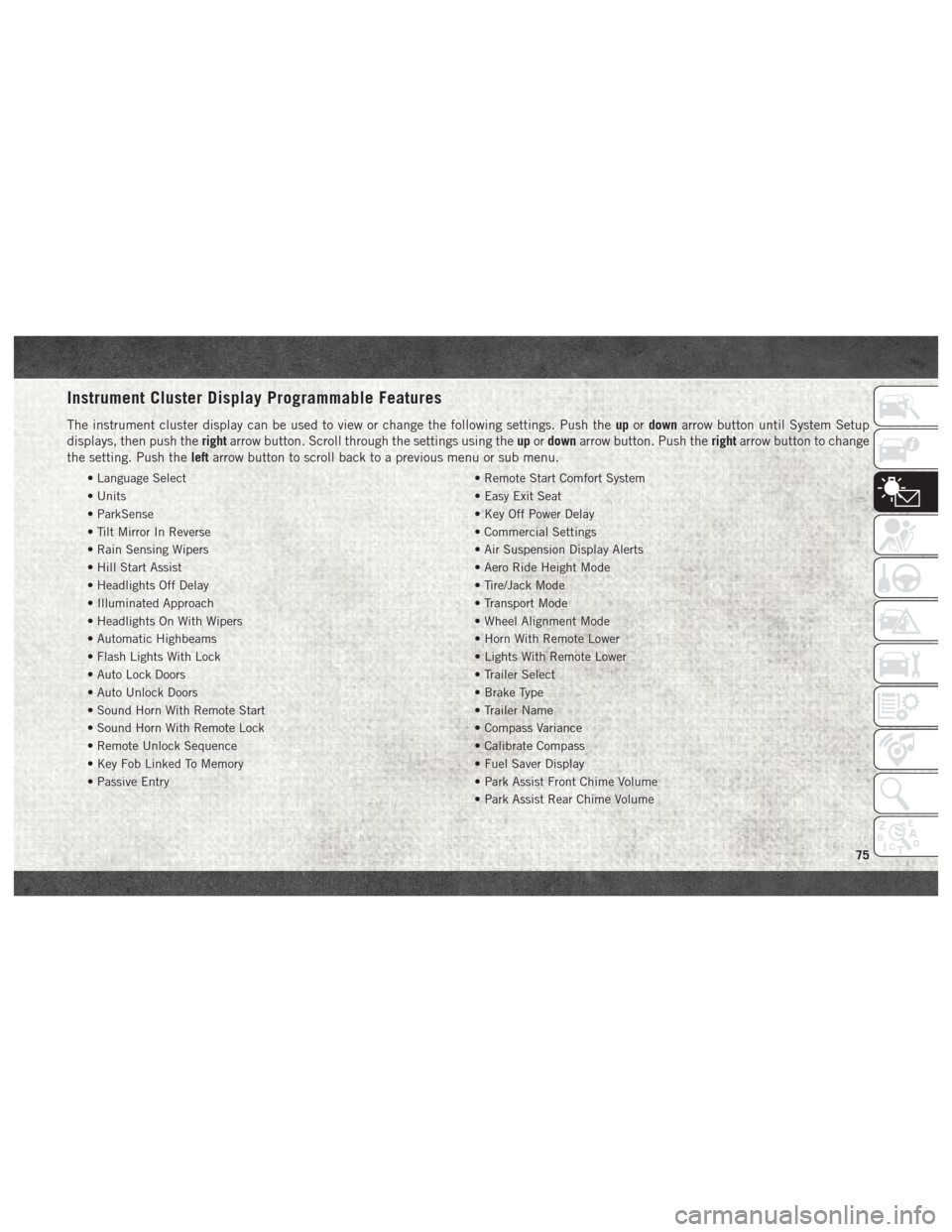
Instrument Cluster Display Programmable Features
The instrument cluster display can be used to view or change the following settings. Push theupordown arrow button until System Setup
displays, then push the rightarrow button. Scroll through the settings using the upordown arrow button. Push the rightarrow button to change
the setting. Push the leftarrow button to scroll back to a previous menu or sub menu.
• Language Select • Remote Start Comfort System
• Units • Easy Exit Seat
• ParkSense • Key Off Power Delay
• Tilt Mirror In Reverse • Commercial Settings
• Rain Sensing Wipers • Air Suspension Display Alerts
• Hill Start Assist • Aero Ride Height Mode
• Headlights Off Delay • Tire/Jack Mode
• Illuminated Approach • Transport Mode
• Headlights On With Wipers • Wheel Alignment Mode
• Automatic Highbeams • Horn With Remote Lower
• Flash Lights With Lock • Lights With Remote Lower
• Auto Lock Doors • Trailer Select
• Auto Unlock Doors • Brake Type
• Sound Horn With Remote Start • Trailer Name
• Sound Horn With Remote Lock • Compass Variance
• Remote Unlock Sequence • Calibrate Compass
• Key Fob Linked To Memory • Fuel Saver Display
• Passive Entry • Park Assist Front Chime Volume
• Park Assist Rear Chime Volume
75
Page 116 of 372
have skin or eye irritation, rinse the area
with cool water. For nose or throat irritation,
move to fresh air. If the irritation continues,
see your doctor. If these particles settle on
your clothing, follow the garment manufac-
turer’s instructions for cleaning.
Do not drive your vehicle after the air bags
have deployed. If you are involved in another
collision, the air bags will not be in place to
protect you.
WARNING!
Deployed air bags and seat belt preten-
sioners cannot protect you in another col-
lision. Have the air bags, seat belt preten-
sioners, and the seat belt retractor
assemblies replaced by an authorized
dealer immediately. Also, have the Occu-
pant Restraint Controller System serviced
as well.
NOTE:
• Air bag covers may not be obvious in the interior trim, but they will open during air
bag deployment. • After any collision, the vehicle should be
taken to an authorized dealer immediately.
Enhanced Accident Response System
In the event of an impact, if the communica-
tion network remains intact, and the power
remains intact, depending on the nature of
the event, the ORC will determine whether to
have the Enhanced Accident Response Sys-
tem perform the following functions:
• Cut off fuel to the engine.
• Flash hazard lights as long as the batteryhas power or until the hazard light button is
pressed. The hazard lights can be deacti-
vated by pressing the hazard light button.
• Turn on the interior lights, which remain on as long as the battery has power.
• Unlock the power door locks.
Enhanced Accident Response System Reset
Procedure
In order to reset the Enhanced Accident Re-
sponse System functions after an event, the
ignition switch must be changed from igni-
tion START or ON/RUN to ignition OFF. Care-
fully check the vehicle for fuel leaks in the engine compartment and on the ground near
the engine compartment and fuel tank before
resetting the system and starting the engine.
Maintaining Your Air Bag System
WARNING!
• Modifications to any part of the air bag
system could cause it to fail when you
need it. You could be injured if the air
bag system is not there to protect you.
Do not modify the components or wiring,
including adding any kind of badges or
stickers to the steering wheel hub trim
cover or the upper right side of the
instrument panel. Do not modify the
front bumper, vehicle body structure, or
add aftermarket side steps or running
boards.
• It is dangerous to try to repair any part of
the air bag system yourself. Be sure to
tell anyone who works on your vehicle
that it has an air bag system.
• Do not attempt to modify any part of your
air bag system. The air bag may inflate
accidentally or may not function prop-
SAFETY
114
Page 138 of 372
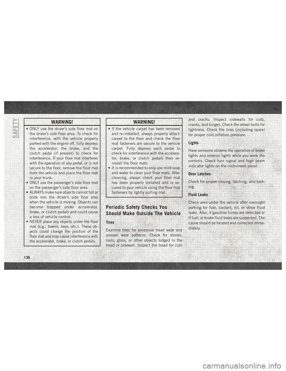
WARNING!
• ONLY use the driver’s side floor mat onthe driver’s side floor area. To check for
interference, with the vehicle properly
parked with the engine off, fully depress
the accelerator, the brake, and the
clutch pedal (if present) to check for
interference. If your floor mat interferes
with the operation of any pedal, or is not
secure to the floor, remove the floor mat
from the vehicle and place the floor mat
in your trunk.
• ONLY use the passenger’s side floor mat
on the passenger’s side floor area.
• ALWAYS make sure objects cannot fall or
slide into the driver’s side floor area
when the vehicle is moving. Objects can
become trapped under accelerator,
brake, or clutch pedals and could cause
a loss of vehicle control.
•
NEVER place any objects under the floor
mat (e.g., towels, keys, etc.). These ob-
jects could change the position of the
floor mat and may cause interference with
the accelerator, brake, or clutch pedals.
WARNING!
• If the vehicle carpet has been removed
and re-installed, always properly attach
carpet to the floor and check the floor
mat fasteners are secure to the vehicle
carpet. Fully depress each pedal to
check for interference with the accelera-
tor, brake, or clutch pedals then re-
install the floor mats.
• It is recommended to only use mild soap
and water to clean your floor mats. After
cleaning, always check your floor mat
has been properly installed and is se-
cured to your vehicle using the floor mat
fasteners by lightly pulling mat.
Periodic Safety Checks You
Should Make Outside The Vehicle
Tires
Examine tires for excessive tread wear and
uneven wear patterns. Check for stones,
nails, glass, or other objects lodged in the
tread or sidewall. Inspect the tread for cuts and cracks. Inspect sidewalls for cuts,
cracks, and bulges. Check the wheel bolts for
tightness. Check the tires (including spare)
for proper cold inflation pressure.
Lights
Have someone observe the operation of brake
lights and exterior lights while you work the
controls. Check turn signal and high beam
indicator lights on the instrument panel.
Door Latches
Check for proper closing, latching, and lock-
ing.
Fluid Leaks
Check area under the vehicle after overnight
parking for fuel, coolant, oil, or other fluid
leaks. Also, if gasoline fumes are detected or
if fuel, or brake fluid leaks are suspected. The
cause should be located and corrected imme-
diately.
SAFETY
136
Page 147 of 372
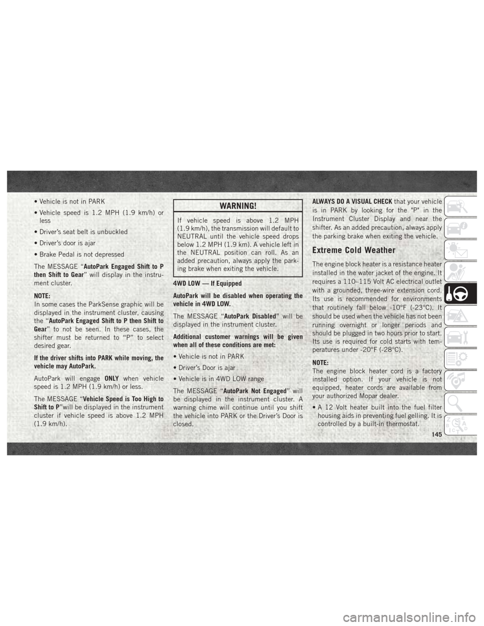
• Vehicle is not in PARK
• Vehicle speed is 1.2 MPH (1.9 km/h) orless
• Driver’s seat belt is unbuckled
• Driver’s door is ajar
• Brake Pedal is not depressed
The MESSAGE “AutoPark Engaged Shift to P
then Shift to Gear” will display in the instru-
ment cluster.
NOTE:
In some cases the ParkSense graphic will be
displayed in the instrument cluster, causing
the “AutoPark Engaged Shift to P then Shift to
Gear” to not be seen. In these cases, the
shifter must be returned to “P” to select
desired gear.
If the driver shifts into PARK while moving, the
vehicle may AutoPark.
AutoPark will engage ONLYwhen vehicle
speed is 1.2 MPH (1.9 km/h) or less.
The MESSAGE “Vehicle Speed is Too High to
Shift to P”will be displayed in the instrument
cluster if vehicle speed is above 1.2 MPH
(1.9 km/h).WARNING!
If vehicle speed is above 1.2 MPH
(1.9 km/h), the transmission will default to
NEUTRAL until the vehicle speed drops
below 1.2 MPH (1.9 km). A vehicle left in
the NEUTRAL position can roll. As an
added precaution, always apply the park-
ing brake when exiting the vehicle.
4WD LOW — If Equipped
AutoPark will be disabled when operating the
vehicle in 4WD LOW.
The MESSAGE “AutoPark Disabled” will be
displayed in the instrument cluster.
Additional customer warnings will be given
when all of these conditions are met:
• Vehicle is not in PARK
• Driver’s Door is ajar
• Vehicle is in 4WD LOW range
The MESSAGE “AutoPark Not Engaged” will
be displayed in the instrument cluster. A
warning chime will continue until you shift
the vehicle into PARK or the Driver’s Door is
closed. ALWAYS DO A VISUAL CHECK
that your vehicle
is in PARK by looking for the "P" in the
Instrument Cluster Display and near the
shifter. As an added precaution, always apply
the parking brake when exiting the vehicle.
Extreme Cold Weather
The engine block heater is a resistance heater
installed in the water jacket of the engine. It
requires a 110–115 Volt AC electrical outlet
with a grounded, three-wire extension cord.
Its use is recommended for environments
that routinely fall below -10°F (-23°C). It
should be used when the vehicle has not been
running overnight or longer periods and
should be plugged in two hours prior to start.
Its use is required for cold starts with tem-
peratures under -20°F (-28°C).
NOTE:
The engine block heater cord is a factory
installed option. If your vehicle is not
equipped, heater cords are available from
your authorized Mopar dealer.
• A 12 Volt heater built into the fuel filter housing aids in preventing fuel gelling. It is
controlled by a built-in thermostat.
145
Page 150 of 372
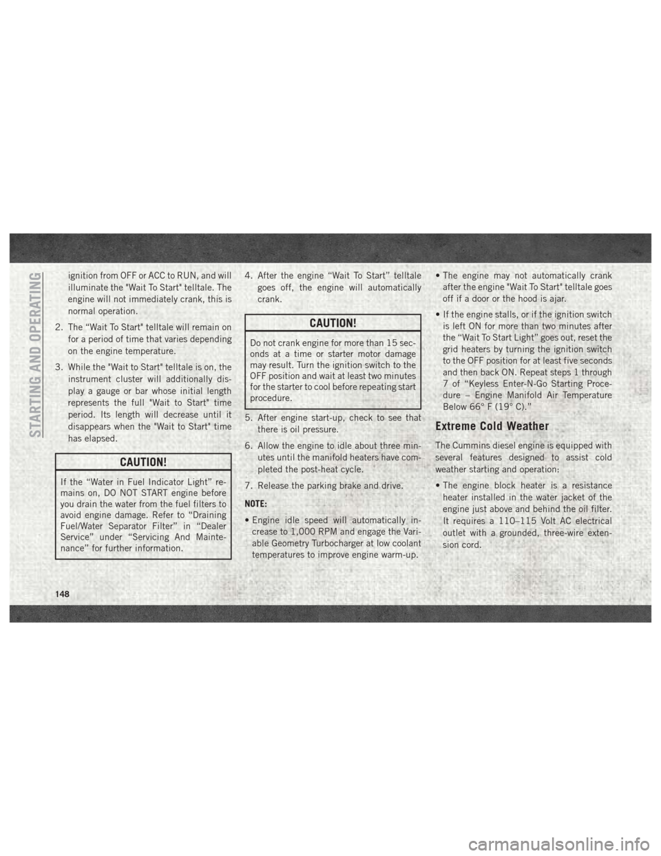
ignition from OFF or ACC to RUN, and will
illuminate the "Wait To Start" telltale. The
engine will not immediately crank, this is
normal operation.
2. The “Wait To Start" telltale will remain on for a period of time that varies depending
on the engine temperature.
3. While the "Wait to Start" telltale is on, the instrument cluster will additionally dis-
play a gauge or bar whose initial length
represents the full "Wait to Start" time
period. Its length will decrease until it
disappears when the "Wait to Start" time
has elapsed.
CAUTION!
If the “Water in Fuel Indicator Light” re-
mains on, DO NOT START engine before
you drain the water from the fuel filters to
avoid engine damage. Refer to “Draining
Fuel/Water Separator Filter” in “Dealer
Service” under “Servicing And Mainte-
nance” for further information. 4. After the engine “Wait To Start” telltale
goes off, the engine will automatically
crank.
CAUTION!
Do not crank engine for more than 15 sec-
onds at a time or starter motor damage
may result. Turn the ignition switch to the
OFF position and wait at least two minutes
for the starter to cool before repeating start
procedure.
5. After engine start-up, check to see that there is oil pressure.
6. Allow the engine to idle about three min- utes until the manifold heaters have com-
pleted the post-heat cycle.
7. Release the parking brake and drive.
NOTE:
• Engine idle speed will automatically in- crease to 1,000 RPM and engage the Vari-
able Geometry Turbocharger at low coolant
temperatures to improve engine warm-up. • The engine may not automatically crank
after the engine "Wait To Start" telltale goes
off if a door or the hood is ajar.
• If the engine stalls, or if the ignition switch is left ON for more than two minutes after
the “Wait To Start Light” goes out, reset the
grid heaters by turning the ignition switch
to the OFF position for at least five seconds
and then back ON. Repeat steps 1 through
7 of “Keyless Enter-N-Go Starting Proce-
dure – Engine Manifold Air Temperature
Below 66° F (19° C).”
Extreme Cold Weather
The Cummins diesel engine is equipped with
several features designed to assist cold
weather starting and operation:
• The engine block heater is a resistance
heater installed in the water jacket of the
engine just above and behind the oil filter.
It requires a 110–115 Volt AC electrical
outlet with a grounded, three-wire exten-
sion cord.STARTING AND OPERATING
148
Page 183 of 372

REFUELING THE VEHICLE — GAS
ENGINE
The fuel filler cap (gas cap) is located behind
the fuel filler door, on the left side of the
vehicle. Open the fuel door and remove the
fuel cap by turning it counter-clockwise.
NOTE:
When removing the fuel filler cap, lay the cap
tether in the hook, located on the fuel filler
door.
WARNING!
• Never have any smoking materials lit inor near the vehicle when the gas cap is
removed or the tank is being filled.
• Never add fuel to the vehicle when the
engine is running.
• A fire may result if gasoline is pumped
into a portable container that is inside of
a vehicle. You could be burned. Always
place gas containers on the ground while
filling.
CAUTION!
• Damage to the fuel system or emissionscontrol system could result from using
an improper fuel tank filler tube cap.
• A poorly fitting fuel filler cap could let
impurities into the fuel system.
• A poorly fitting fuel filler cap may cause
the “Malfunction Indicator Light (MIL)”
to turn on.
• To avoid fuel spillage and overfilling, do
not “top off” the fuel tank after filling.
When the fuel nozzle “clicks” or shuts
off, the fuel tank is full.
NOTE:
• When the fuel nozzle “clicks” or shuts off, the fuel tank is full.
• Tighten the gas cap until you hear a “click- ing” sound. This is an indication that the
gas cap is tightened properly. The MIL in
the instrument cluster may turn on if the
gas cap is not secured properly. Make sure
that the gas cap is tightened each time the
vehicle is refueled.
WARNING!
Static electricity can cause an ignition of
flammable liquid, vapor or gas in any ve-
hicle or trailer. To reduce risk of serious
injury or death when filling containers:
• Always place container on the ground before filling.
• Keep the pump nozzle in contact with
the container when you are filling it.
• Use only approved containers for flam-
mable liquid.
• Do not leave container unattended while
filling.
• A static electric charge could cause a
spark and fire hazard.
181
Page 206 of 372

CavityCartridge Fuse Micro Fuse Description
F07 40 Amp Green – Starter Solenoid
F08 20 Amp Blue (1500 LD/
Cummins Diesel) –
Emissions Diesel – If Equipped
F09 40 Amp Green (Special
Services Vehicle & Cum- mins Diesel) –
Diesel Fuel Heater – If Equipped
F10 40 Amp Green –Body Controller / Exterior Lighting #2
F10 50 Amp Red –Body Controller / Exterior Lighting #2 – If Equipped with
Stop/Start
F11 30 Amp Pink –Integrated Trailer Brake Module – If Equipped
F12 40 Amp Green –Body Controller #3 / Power Locks
F13 40 Amp Green – Blower Motor
F14 40 Amp Green –Body Controller #4 / Interior Lighting
F16 30 Amp Pink –Smart Bar – If Equipped
F19 20 Amp Blue (1500 LD
Diesel)
30 Amp Pink (Cummins Diesel) –
SCR – If Equipped
F20 30 Amp Pink –Passenger Door Module
F21 30 Amp Pink –Drive Train Control Module
F22 20 Amp Blue
30 Amp Pink (Cummins Diesel) –
Engine Control Module
F23 30 Amp Pink –Body Controller #1 / Interior Lighting
F24 30 Amp Pink –Driver Door Module
IN CASE OF EMERGENCY
204