ABS Ram 3500 2018 User Guide
[x] Cancel search | Manufacturer: RAM, Model Year: 2018, Model line: 3500, Model: Ram 3500 2018Pages: 372, PDF Size: 7.1 MB
Page 4 of 372
HOW TO USE THIS MANUAL
Essential Information
Each time direction instructions (left/right or
forwards/backwards) about the vehicle are
given, these must be intended as regarding
an occupant in the driver's seat. Special
cases not complying with this rule will be
properly specified in the text.
The figures in this User Guide are provided by
way of example only: this might imply that
some details of the image do not correspond
to the actual arrangement of your vehicle.
In addition, the User Guide has been conceived
considering vehicles with steering wheel on the
left side; it is therefore possible that on vehicles
with steering wheel on the right side, the posi-
tion or construction of some controls is not
exactly mirror-like with respect to the figure.
To identify the chapter with the information
needed you can consult the index at the end
of this User Guide.
Chapters can be rapidly identified with dedi-
cated graphic tabs, at the side of each oddpage. A few pages further there is a key for
getting to know the chapter order and the
relevant symbols in the tabs. There is anyway
a textual indication of the current chapter at
the side of each even page.
Symbols
Some vehicle components have colored la-
bels whose symbols indicate precautions to
be observed when using this component.
WARNINGS AND CAUTIONS
While reading this User Guide you will find a
series of WARNINGS to be followed to pre-
vent incorrect use of components which
could cause accidents or injuries.
There are also CAUTIONS that must be fol-
lowed to prevent against procedures that
could result in damage to your vehicle.
VAN CONVERSIONS/CAMPERS
The New Vehicle Limited Warranty does not
apply to body modifications or special equip-
ment installed by van conversion/camper
manufacturers/body builders. U.S. residents
refer to the Warranty Information book, Section
2.1.C. Canadian residents refer to the “What Is
Not Covered” section of the Warranty Informa-
tion book. Such equipment includes video
monitors, VCRs, heaters, stoves, refrigerators,
etc. For warranty coverage and service on these
items, contact the applicable manufacturer.
Operating instructions for the special equip-
ment installed by the conversion/camper
manufacturer should also be supplied with
your vehicle. If these instructions are miss-
ing, please contact your authorized dealer for
assistance in obtaining replacement docu-
ments from the applicable manufacturer.
For information on the Body Builder’s Guide
refer to www.rambodybuilder.com. This web-
site contains dimensional and technical
specifications for your vehicle. It is intended
for Second Stage Manufacturer's technical
support. For service issues, contact your au-
thorized dealer.
INTRODUCTION
2
Page 78 of 372
WARNING LIGHTS AND MESSAGES
Red Warning Lights
— Seat Belt Reminder Warning Light
This light indicates when the driver or pas-
senger seat belt is unbuckled. When the
ignition is first placed in the ON/RUN or
ACC/ON/RUN position and if the driver’s seat
belt is unbuckled, a chime will sound and the
light will turn on. When driving, if the driver
or front passenger seat belt remains unbuck-
led, the Seat Belt Reminder Light will flash or
remain on continuously and a chime will
sound. Refer to “Occupant Restraints Sys-
tems” in “Safety” for further information.
— Air Bag Warning Light
This light indicates a fault with the air bag,
and will turn on for four to eight seconds as a
bulb check when the ignition is placed in the
ON/RUN or ACC/ON/RUN position. This light
will illuminate with a single chime when a
fault with the air bag has been detected, it
will stay on until the fault is cleared. If thelight is either not on during startup, stays on,
or turns on while driving, have the system
inspected at an authorized dealer as soon as
possible.
— Brake Warning Light
This light monitors various brake functions,
including brake fluid level and parking brake
application. If the brake light turns on it may
indicate that the parking brake is applied,
that the brake fluid level is low, or that there
is a problem with the anti-lock brake system
reservoir.
If the light remains on when the parking brake
has been disengaged, and the fluid level is at
the full mark on the master cylinder reservoir, it
indicates a possible brake hydraulic system
malfunction or that a problem with the Brake
Booster has been detected by the Anti-Lock
Brake System (ABS) / Electronic Stability Con-
trol (ESC) system. In this case, the light will
remain on until the condition has been cor-
rected. If the problem is related to the brake
booster, the ABS pump will run when applying
the brake, and a brake pedal pulsation may be
felt during each stop.
The dual brake system provides a reserve
braking capacity in the event of a failure to a
portion of the hydraulic system. A leak in
either half of the dual brake system is indi-
cated by the Brake Warning Light, which will
turn on when the brake fluid level in the
master cylinder has dropped below a speci-
fied level.
The light will remain on until the cause is
corrected.
NOTE:
The light may flash momentarily during sharp
cornering maneuvers, which change fluid level
conditions. The vehicle should have service
performed, and the brake fluid level checked.
If brake failure is indicated, immediate repair
is necessary.
WARNING!
Driving a vehicle with the red brake light
on is dangerous. Part of the brake system
may have failed. It will take longer to stop
the vehicle. You could have a collision.
Have the vehicle checked immediately.
GETTING TO KNOW YOUR INSTRUMENT PANEL
76
Page 79 of 372
Vehicles equipped with the Anti-Lock Brake
System (ABS) are also equipped with Elec-
tronic Brake Force Distribution (EBD). In the
event of an EBD failure, the Brake Warning
Light will turn on along with the ABS Light.
Immediate repair to the ABS system is re-
quired.
Operation of the Brake Warning Light can be
checked by turning the ignition switch from
the OFF position to the ON/RUN position.
The light should illuminate for approximately
two seconds. The light should then turn off
unless the parking brake is applied or a brake
fault is detected. If the light does not illumi-
nate, have the light inspected by your autho-
rized dealer.
The light also will turn on when the parking
brake is applied with the ignition switch in
the ON/RUN position.
NOTE:
This light shows only that the parking brake is
applied. It does not show the degree of brake
application.— Vehicle Security Warning Light — If
Equipped
This light will flash at a fast rate for approxi-
mately 15 seconds when the vehicle security
alarm is arming, and then will flash slowly
until the vehicle is disarmed.
— Engine Coolant Temperature Warn-
ing Light
This light warns of an overheated engine
condition. If the engine coolant temperature
is too high, this indicator will illuminate and a
single chime will sound. If the temperature
reaches the upper limit, a continuous chime
will be sound for four minutes or until the
engine is able to cool: whichever comes first.
If the light turns on while driving, safely pull
over and stop the vehicle. If the A/C system is
on, turn it off. Also, shift the transmission
into NEUTRAL and idle the vehicle. If the
temperature reading does not return to nor-
mal, turn the engine off immediately and call
for service. Refer to “If Your Engine Over-
heats” in “In Case Of Emergency” for further
information.
— Battery Charge Warning Light
This light illuminates when the battery is not
charging properly. If it stays on while the
engine is running, there may be a malfunc-
tion with the charging system. Contact your
authorized dealer as soon as possible.
This indicates a possible problem with the
electrical system or a related component.
— Oil Pressure Warning Light
This light indicates low engine oil pressure. If
the light turns on while driving, stop the
vehicle and shut off the engine as soon as
possible. A chime will sound when this light
turns on.
Do not operate the vehicle until the cause is
corrected. This light does not indicate how
much oil is in the engine. The engine oil level
must be checked under the hood.
— Electronic Throttle Control (ETC)
Warning Light
This light informs you of a problem with the
Electronic Throttle Control (ETC) system. If a
problem is detected while the vehicle is run-
ning, the light will either stay on or flash
77
Page 83 of 372
CAUTION!
of the same size, type, and/or style. After-
market wheels can cause sensor damage.
Using aftermarket tire sealants may cause
the Tire Pressure Monitoring System
(TPMS) sensor to become inoperable. Af-
ter using an aftermarket tire sealant it is
recommended that you take your vehicle
to your authorized dealer to have your
sensor function checked.
— Low Fuel Indicator Light
When the fuel level reaches approximately
3.0 gal (11.0 L) this light will turn on, and
remain on until fuel is added.
— Anti-Lock Brake (ABS) Warning
Light
This light monitors the Anti-Lock Brake Sys-
tem (ABS). The light will turn on when the
ignition is placed in the ON/RUN or ACC/ON/
RUN position and may stay on for as long as
four seconds. If the ABS light remains on or turns on while
driving, then the Anti-Lock portion of the
brake system is not functioning and service is
required as soon as possible. However, the
conventional brake system will continue to
operate normally, assuming the Brake Warn-
ing Light is not also on.
If the ABS light does not turn on when the
ignition is placed in the ON/RUN or ACC/ON/
RUN position, have the brake system in-
spected by an authorized dealer.
— Low Coolant Level Warning Light
This telltale will turn on to indicate the ve-
hicle coolant level is low.
— Loose Fuel Filler Cap Warning Light
— If Equipped
This light will illuminate when the fuel filler
cap is loose. Properly close the filler cap to
disengage the light. If the light does not turn
off, please see your authorized dealer.
SERV4WD— Service 4WD Warning Light — If
Equipped
If the light stays on or comes on during driving,
it means that the 4WD system is not functioning
properly and that service is required. We recom-
mend you drive to the nearest service center and
have the vehicle serviced immediately.
— Transmission Temperature Warning
Light
This light indicates that the transmission
fluid temperature is running hot. This may
occur with severe usage, such as trailer tow-
ing. If this light turns on, safely pull over and
stop the vehicle. Then, shift the transmission
into PARK and run the engine at idle or
slightly higher until the light turns off.
WARNING!
If you continue operating the vehicle when
the Transmission Temperature Warning
Light is illuminated you could cause the
fluid to boil over, come in contact with hot
engine or exhaust components and cause a
fire.
81
Page 109 of 372
Because air bag sensors measure vehicle de-
celeration over time, vehicle speed and dam-
age by themselves are not good indicators of
whether or not an air bag should have de-
ployed.
Seat belts are necessary for your protection in
all collisions, and also are needed to help
keep you in position, away from an inflating
air bag.
When the ORC detects a collision requiring
the front air bags, it signals the inflator units.
A large quantity of non-toxic gas is generated
to inflate the front air bags.
The steering wheel hub trim cover and the
upper right side of the instrument panel
separate and fold out of the way as the air
bags inflate to their full size. The front air
bags fully inflate in less time than it takes to
blink your eyes. The front air bags then
quickly deflate while helping to restrain the
driver and front passenger.Knee Impact Bolsters
The Knee Impact Bolsters help protect the
knees of the driver and front passenger, and
position the front occupants for improved
interaction with the front air bags.
WARNING!
• Do not drill, cut, or tamper with the kneeimpact bolsters in any way.
• Do not mount any accessories to the
knee impact bolsters such as alarm
lights, stereos, citizen band radios, etc.
Supplemental Side Air Bags
Ram 1500
Supplemental Seat-Mounted Side Air Bags
(SABs)
This vehicle is equipped with Supplemental
Seat-Mounted Side Air Bags (SABs).
Supplemental Seat-Mounted Side Air Bags
(SABs) are located in the outboard side of the
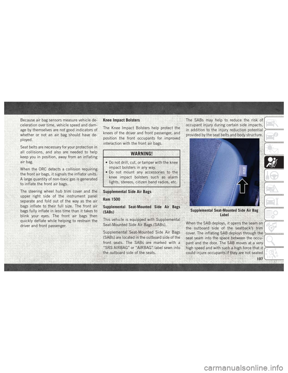
front seats. The SABs are marked with a
“SRS AIRBAG” or “AIRBAG” label sewn into
the outboard side of the seats. The SABs may help to reduce the risk of
occupant injury during certain side impacts,
in addition to the injury reduction potential
provided by the seat belts and body structure.
When the SAB deploys, it opens the seam on
the outboard side of the seatback’s trim
cover. The inflating SAB deploys through the
seat seam into the space between the occu-
pant and the door. The SAB moves at a very
high speed and with such a high force that it
could injure occupants if they are not seated
Supplemental Seat-Mounted Side Air Bag
Label
107
Page 112 of 372

Rollover Events
Side Air Bags are designed to activate in
certain rollover events. The Occupant Re-
straint Controller (ORC) determines whether
the deployment of the Side Air Bags in a
particular rollover event is appropriate, based
on the severity and type of collision. Vehicle
damage by itself is not a good indicator of
whether or not Side Air Bags should have
deployed.
The Side Air Bags will not deploy in all
rollover events. The rollover sensing-system
determines if a rollover event may be in
progress and whether deployment is appro-
priate. A slower-developing event may deploy
the seat belt pretensioners on both sides of
the vehicle. A faster-developing event may
deploy the seat belt pretensioners as well as
the Side Air Bags on both sides of the vehicle.
The rollover sensing-system may also deploy
the seat belt pretensioners, with or without
the Side Air Bags, on both sides of the vehicle
if the vehicle experiences a near rollover
event.The SABICs may help reduce the risk of
partial or complete ejection of vehicle occu-
pants through side windows in certain roll-
over or side impact events.
Ram 2500 And 3500
Supplemental Seat-Mounted Side Air Bags
(SABs) — If Equipped
Your vehicle may be equipped with Supple-
mental Seat-Mounted Side Air Bags (SABs).
If your vehicle is equipped with Supplemen-
tal Seat-Mounted Side Air Bags (SABs),
please refer to the information below.
Supplemental Seat-Mounted Side Air Bags
(SABs) are located in the outboard side of the
front seats. The SABs are marked with a
“SRS AIRBAG” or “AIRBAG” label sewn into
the outboard side of the seats.
The SABs (if equipped with SABs) may help
to reduce the risk of occupant injury during
certain side impacts, in addition to the injury
reduction potential provided by the seat belts
and body structure.
When the SAB deploys, it opens the seam on
the outboard side of the seatback’s trim
cover. The inflating SAB deploys through the
seat seam into the space between the occu-
pant and the door. The SAB moves at a very
Supplemental Seat-Mounted Side Air Bag
Label
SAFETY
110
Page 123 of 372

Frequently Asked Questions About Installing Child Restraints With LATCH
What is the weight limit (child’s weight +
weight of the child restraint) for using the
LATCH anchorage system to attach the child restraint? 65 lbs (29.5 kg)Use the LATCH anchorage system until the
combined weight of the child and the child
restraint is 65 lbs (29.5 kg). Use the seat belt
and tether anchor instead of the LATCH system once the combined weight is more than 65 lbs (29.5 kg).
Quad Cab 60/40 Split Bench LATCHPositions
Lower Anchorage Symbol (2 An-
chorages Per Seating Position)
Top Tether Anchorage SymbolCrew/Mega Cabs 60/40 Split Bench
LATCH Positions
Lower Anchorage Symbol (2 An-
chorages Per Seating Position)
Top Tether Anchorage Symbol
Quad/Crew Cabs Full Bench LATCH
Positions
Lower Anchorage Symbol (2 An-
chorages Per Seating Position)
Top Tether Anchorage Symbol
121
Page 215 of 372
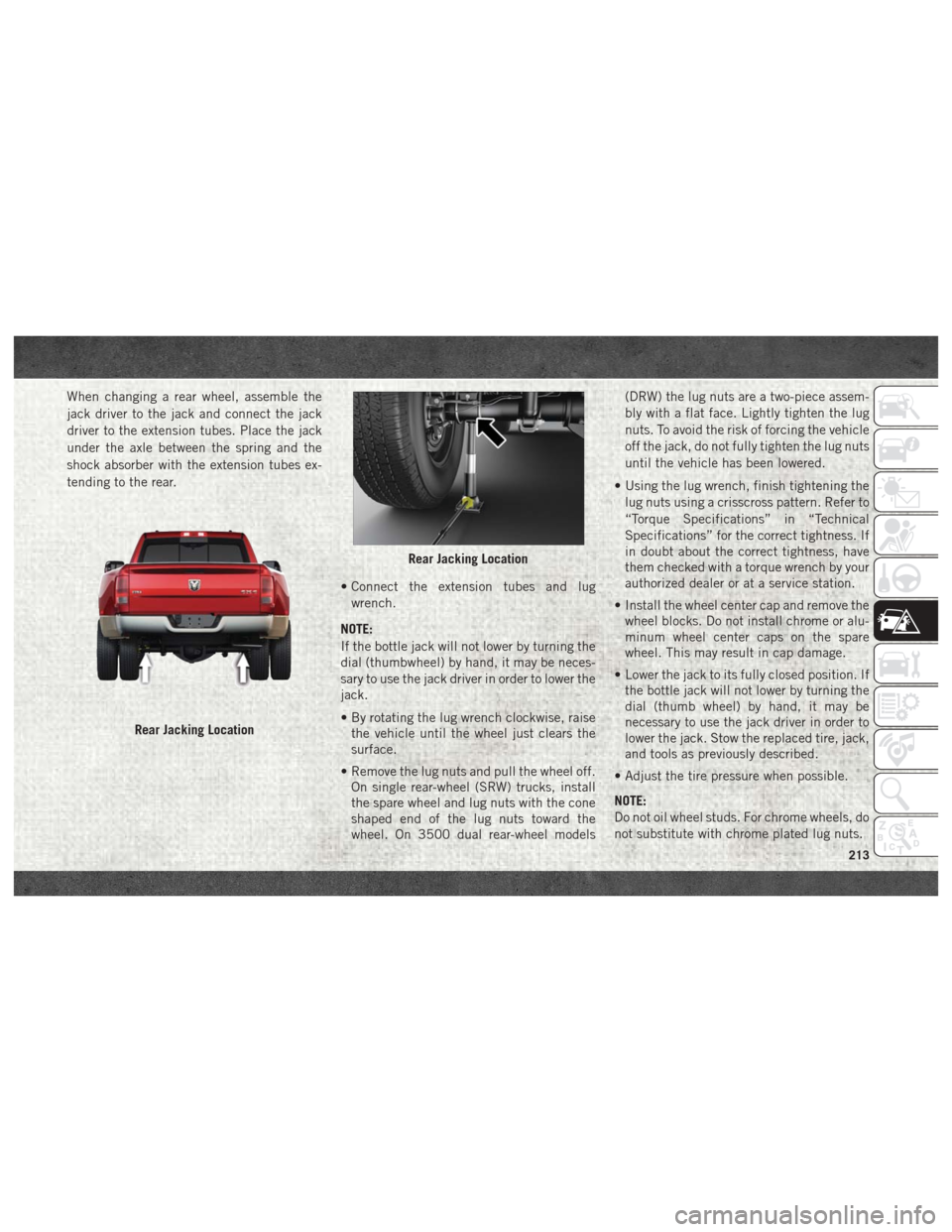
When changing a rear wheel, assemble the
jack driver to the jack and connect the jack
driver to the extension tubes. Place the jack
under the axle between the spring and the
shock absorber with the extension tubes ex-
tending to the rear.• Connect the extension tubes and lugwrench.
NOTE:
If the bottle jack will not lower by turning the
dial (thumbwheel) by hand, it may be neces-
sary to use the jack driver in order to lower the
jack.
• By rotating the lug wrench clockwise, raise the vehicle until the wheel just clears the
surface.
• Remove the lug nuts and pull the wheel off. On single rear-wheel (SRW) trucks, install
the spare wheel and lug nuts with the cone
shaped end of the lug nuts toward the
wheel. On 3500 dual rear-wheel models (DRW) the lug nuts are a two-piece assem-
bly with a flat face. Lightly tighten the lug
nuts. To avoid the risk of forcing the vehicle
off the jack, do not fully tighten the lug nuts
until the vehicle has been lowered.
• Using the lug wrench, finish tightening the lug nuts using a crisscross pattern. Refer to
“Torque Specifications” in “Technical
Specifications” for the correct tightness. If
in doubt about the correct tightness, have
them checked with a torque wrench by your
authorized dealer or at a service station.
• Install the wheel center cap and remove the wheel blocks. Do not install chrome or alu-
minum wheel center caps on the spare
wheel. This may result in cap damage.
• Lower the jack to its fully closed position. If the bottle jack will not lower by turning the
dial (thumb wheel) by hand, it may be
necessary to use the jack driver in order to
lower the jack. Stow the replaced tire, jack,
and tools as previously described.
• Adjust the tire pressure when possible.
NOTE:
Do not oil wheel studs. For chrome wheels, do
not substitute with chrome plated lug nuts.
Rear Jacking Location
Rear Jacking Location
213
Page 259 of 372

HOISTING
A conventional floor jack may be used at the
jacking locations. Refer to the graphics that
show jacking locations. However, a floor jack
or frame hoist must never be used on any
other parts of the underbody.
CAUTION!
Never use a floor jack directly under the
differential housing of a loaded truck or
damage to your vehicle may result.
TIRES
Tire Safety Information
Tire safety information will cover aspects of
the following information: Tire Markings, Tire
Identification Numbers, Tire Terminology and
Definitions, Tire Pressures, and Tire Loading.
Tire MarkingsNOTE:
• P (Passenger) — Metric tire sizing is basedon U.S. design standards. P-Metric tires
have the letter “P” molded into the sidewall
preceding the size designation. Example:
P215/65R15 95H.
• European — Metric tire sizing is based on European design standards. Tires designed
to this standard have the tire size molded
into the sidewall beginning with the section
width. The letter "P" is absent from this tire
size designation. Example: 215/
65R15 96H.
• LT (Light Truck) — Metric tire sizing is based on U.S. design standards. The size
designation for LT-Metric tires is the same
as for P-Metric tires except for the letters
“LT” that are molded into the sidewall pre-
ceding the size designation. Example:
LT235/85R16.
• Temporary spare tires are designed for tem- porary emergency use only. Temporary high
pressure compact spare tires have the letter
“T” or “S” molded into the sidewall preced-
ing the size designation. Example: T145/
80D18 103M.
Tire Markings
1 — U.S. DOT
Safety Stan-
dards Code
(TIN) 4 — Maximum
Load
2 — Size Desig-
nation 5 — Maximum
Pressure
3 — Service
Description 6 — Treadwear,
Traction and
Temperature
Grades
257
Page 261 of 372

EXAMPLE:
H = Speed Symbol
• A symbol indicating the range of speeds at which a tire can carry a load corresponding to its load index under certain operating conditions
• The maximum speed corresponding to the speed symbol should only be achieved under specified operating conditions (i.e., tire pressure, vehicle
loading, road conditions, and posted speed limits)
Load Identification:
Absence of the following load identification symbols on the sidewall of the tire indicates a Standard Load (SL) tire:
• XL= Extra load (or reinforced) tire, or
• LL= Light load tire or
• C, D, E, F, G = Load range associated with the maximum load a tire can carry at a specified pressure
Maximum Load – Maximum load indicates the maximum load this tire is designed to carry
Maximum Pressure – Maximum pressure indicates the maximum permissible cold tire inflation pressure for this tire
Tire Identification Number (TIN)
The TIN may be found on one or both sides of
the tire; however, the date code may only be
on one side. Tires with white sidewalls will
have the full TIN, including the date code, located on the white sidewall side of the tire.
Look for the TIN on the outboard side of black
sidewall tires as mounted on the vehicle. If
the TIN is not found on the outboard side,
then you will find it on the inboard side of the
tire.
EXAMPLE:
DOT MA L9 ABCD 0301
DOT = Department of Transportation
• This symbol certifies that the tire is in compliance with the U.S. Department of Transportation tire safety standards and is approved for highway
use
MA = Code representing the tire manufacturing location (two digits)
L9 = Code representing the tire size (two digits)
259