bulb Ram 3500 2018 User Guide
[x] Cancel search | Manufacturer: RAM, Model Year: 2018, Model line: 3500, Model: Ram 3500 2018Pages: 372, PDF Size: 7.1 MB
Page 35 of 372
Automatic High Beam Headlamp
Control — If Equipped
The Automatic High Beam Headlamp Control
system provides increased forward lighting at
night by automating high beam control
through the use of a digital camera mounted
on the inside rearview mirror. This camera
detects vehicle specific light and automati-
cally switches from high beams to low beams
until the approaching vehicle is out of view.
NOTE:
• The Automatic High Beam Headlamp Con-trol can be turned on or off by selecting
“ON” under “Auto High Beam” within your
Uconnect settings, as well as turning the
headlight switch to the AUTO position. Re-
fer to “Uconnect Settings” in “Multimedia”
in the Owner’s Manual for further informa-
tion.
• Broken, muddy, or obstructed headlights and taillights of vehicles in the field of view
will cause headlights to remain on longer
(closer to the vehicle). Also, dirt, film, and
other obstructions on the windshield or
camera lens will cause the system to func-
tion improperly. If the windshield or Automatic High Beam
Headlamp Control mirror is replaced, the
mirror must be re-aimed to ensure proper
performance. See a local authorized dealer.
Automatic Headlights — If
Equipped
This system automatically turns the head-
lights on or off according to ambient light
levels. To turn the system on, rotate the
headlight switch counterclockwise to the
AUTO position. When the system is on, the
headlight time delay feature is also on. This
means the headlights will stay on for up to
90 seconds after you place the ignition into
the OFF position. The headlight time delay
can be programmed 0/30/60/90 seconds.
Refer to “Uconnect Settings” in “Multime-
dia” in the Owner’s Manual for further infor-
mation.
To turn the automatic system off, move the
headlight switch out of the AUTO position.
NOTE:
The engine must be running before the head-
lights will turn on in the Automatic Mode.
Parking Lights And Panel Lights
To turn on the parking lights and instrument
panel lights, rotate the headlight switch
clockwise. To turn off the parking lights,
rotate the headlight switch back to the O (off)
position.
Turn Signals
Move the multifunction lever up or down and
the arrows on each side of the instrument
cluster display will flash to show proper op-
eration of the front and rear turn signal lights.
NOTE:
If either light remains on and does not flash,
or there is a very fast flash rate, check for a
defective outside light bulb. If an indicator
fails to light when the lever is moved, it would
suggest that the indicator bulb is defective.
33
Page 78 of 372
WARNING LIGHTS AND MESSAGES
Red Warning Lights
— Seat Belt Reminder Warning Light
This light indicates when the driver or pas-
senger seat belt is unbuckled. When the
ignition is first placed in the ON/RUN or
ACC/ON/RUN position and if the driver’s seat
belt is unbuckled, a chime will sound and the
light will turn on. When driving, if the driver
or front passenger seat belt remains unbuck-
led, the Seat Belt Reminder Light will flash or
remain on continuously and a chime will
sound. Refer to “Occupant Restraints Sys-
tems” in “Safety” for further information.
— Air Bag Warning Light
This light indicates a fault with the air bag,
and will turn on for four to eight seconds as a
bulb check when the ignition is placed in the
ON/RUN or ACC/ON/RUN position. This light
will illuminate with a single chime when a
fault with the air bag has been detected, it
will stay on until the fault is cleared. If thelight is either not on during startup, stays on,
or turns on while driving, have the system
inspected at an authorized dealer as soon as
possible.
— Brake Warning Light
This light monitors various brake functions,
including brake fluid level and parking brake
application. If the brake light turns on it may
indicate that the parking brake is applied,
that the brake fluid level is low, or that there
is a problem with the anti-lock brake system
reservoir.
If the light remains on when the parking brake
has been disengaged, and the fluid level is at
the full mark on the master cylinder reservoir, it
indicates a possible brake hydraulic system
malfunction or that a problem with the Brake
Booster has been detected by the Anti-Lock
Brake System (ABS) / Electronic Stability Con-
trol (ESC) system. In this case, the light will
remain on until the condition has been cor-
rected. If the problem is related to the brake
booster, the ABS pump will run when applying
the brake, and a brake pedal pulsation may be
felt during each stop.
The dual brake system provides a reserve
braking capacity in the event of a failure to a
portion of the hydraulic system. A leak in
either half of the dual brake system is indi-
cated by the Brake Warning Light, which will
turn on when the brake fluid level in the
master cylinder has dropped below a speci-
fied level.
The light will remain on until the cause is
corrected.
NOTE:
The light may flash momentarily during sharp
cornering maneuvers, which change fluid level
conditions. The vehicle should have service
performed, and the brake fluid level checked.
If brake failure is indicated, immediate repair
is necessary.
WARNING!
Driving a vehicle with the red brake light
on is dangerous. Part of the brake system
may have failed. It will take longer to stop
the vehicle. You could have a collision.
Have the vehicle checked immediately.
GETTING TO KNOW YOUR INSTRUMENT PANEL
76
Page 80 of 372
depending on the nature of the problem.
Cycle the ignition when the vehicle is safely
and completely stopped and the transmission
is placed in the PARK position. The light
should turn off. If the light remains on with
the vehicle running, your vehicle will usually
be drivable; however, see an authorized
dealer for service as soon as possible.
NOTE:
This light may turn on if the accelerator and
brake pedals are pressed at the same time.
If the light continues to flash when the ve-
hicle is running, immediate service is re-
quired and you may experience reduced per-
formance, an elevated/rough idle, or engine
stall and your vehicle may require towing.
The light will come on when the ignition is
placed in the ON/RUN or ACC/ON/RUN posi-
tion and remain on briefly as a bulb check. If
the light does not come on during starting,
have the system checked by an authorized
dealer.— Electric Power Steering Fault
Warning Light
This light will turn on when there's a
fault with the EPS (Electric Power Steering)
system. Refer to “Power Steering” in
“Starting And Operating” in the Owner’s
Manual at
https://www.mopar.com/en-us/care/
owners-manual.html
(U.S. Residents) or
www.owners.mopar.ca (Canadian Residents)
for further information.
WARNING!
Continued operation with reduced assist
could pose a safety risk to yourself and
others. Service should be obtained as soon
as possible.
— Trailer Brake Disconnected Warn-
ing Light
This telltale is on when the Trailer Brake has
been disconnected.
— Door Open Warning Light
This indicator will illuminate when a door is
ajar/open and not fully closed. NOTE:
If the vehicle is moving there will also be a
single chime.
Yellow Warning Lights
— Engine Check/Malfunction Indica-
tor Warning Light (MIL)
The Engine Check/Malfunction Indicator
Light (MIL) is a part of an Onboard Diagnostic
System called OBD II that monitors engine
and automatic transmission control systems.
The light will illuminate when the ignition is
in the ON/RUN position before engine start.
If the bulb does not come on when turning
the ignition switch from OFF to ON/RUN,
have the condition checked promptly.
Certain conditions, such as a loose or missing
gas cap, poor quality fuel, etc., may illumi-
nate the light after engine start. The vehicle
should be serviced if the light stays on
through several typical driving styles. In most
situations, the vehicle will drive normally and
will not require towing.
When the engine is running, the MIL may
flash to alert serious conditions that could
lead to immediate loss of power or severe
GETTING TO KNOW YOUR INSTRUMENT PANEL
78
Page 85 of 372

rotate at the same speed. Low range provides
a greater gear reduction ratio to provide in-
creased torque at the wheels.
Refer to “Four-Wheel Drive Operation — If
Equipped” in “Starting And Operating” for
further information on four-wheel drive op-
eration and proper use.
— Wait To Start Light — If Equipped
The “Wait To Start” telltale will illuminate for
approximately two seconds when the ignition
is turned to the RUN position. It’s duration
may be longer based on colder operating
conditions. Vehicle will not initiate start until
telltale is no longer displayed. Refer to
“Starting The Engine” in “Starting And Op-
erating” for further information.
NOTE:
The “Wait To Start” telltale may not illumi-
nate if the intake manifold temperature is
warm enough.
— Water In Fuel Indicator Light — If
Equipped
The “Water In Fuel Indicator Light” will illu-
minate when there is water detected in the
fuel filters. If this light remains on, DO NOT
start the vehicle before you drain the water
from the fuel filters to prevent engine dam-
age. Refer to the “Draining Fuel/Water Sepa-
rator Filter” section in “Dealer Service” in
“Servicing And Maintenance” for further in-
formation.
— Low Diesel Exhaust Fluid (DEF) Indi-
cator Light — If Equipped
The Low Diesel Exhaust Fluid (DEF) Indicator
will illuminate if the vehicle is low on Diesel
Exhaust Fluid (DEF). Refer to “Starting And
Operating” for further information.
Green Indicator Lights
— Park/Headlight On Indicator Light
This indicator will illuminate when the park
lights or headlights are turned on.
— Front Fog Indicator Light — If
Equipped
This indicator will illuminate when the front
fog lights are on.
— Turn Signal Indicator Lights
When the left or right turn signal is activated,
the turn signal indicator will flash indepen-
dently and the corresponding exterior turn
signal lamps will flash. Turn signals can be
activated when the multifunction lever is
moved down (left) or up (right).
NOTE:
• A continuous chime will sound if the ve- hicle is driven more than 1 mile (1.6 km)
with either turn signal on.
• Check for an inoperative outside light bulb if either indicator flashes at a rapid rate.
—Cruise Control Set Indicator Light —
If Equipped
This light will turn on when the speed control
is set to the desired speed. Refer to “Speed
Control” in “Starting And Operating” for fur-
ther information.
83
Page 107 of 372

• The Air Bag Warning Light does not comeon during the four to eight seconds when
the ignition switch is first in the ON/RUN
position.
• The Air Bag Warning Light remains on after the four to eight-second interval.
• The Air Bag Warning Light comes on inter- mittently or remains on while driving.
NOTE:
If the speedometer, tachometer, or any en-
gine related gauges are not working, the Oc-
cupant Restraint Controller (ORC) may also
be disabled. In this condition the air bags
may not be ready to inflate for your protec-
tion. Have an authorized dealer service the air
bag system immediately.WARNING!
Ignoring the Air Bag Warning Light in your
instrument panel could mean you won’t
have the air bag system to protect you in a
collision. If the light does not come on as a
bulb check when the ignition is first turned
on, stays on after you start the vehicle, or if
it comes on as you drive, have an autho-
rized dealer service the air bag system
immediately.
Front Air Bags
This vehicle has front air bags and lap/
shoulder belts for both the driver and front
passenger. The front air bags are a supple-
ment to the seat belt restraint systems. The
driver front air bag is mounted in the center of
the steering wheel. The passenger front air
bag is mounted in the instrument panel,
above the glove compartment. The words
“SRS AIRBAG” or “AIRBAG” are embossed
on the air bag covers.
WARNING!
• Being too close to the steering wheel or instrument panel during front air bag
deployment could cause serious injury,
Front Air Bag/Knee Bolster Locations
1 — Driver And Passenger Front Air
Bags
2 — Driver And Passenger Knee Impact
Bolsters
105
Page 137 of 372

Front seat belt assemblies must be replaced
after a collision. Rear seat belt assemblies
must be replaced after a collision if they have
been damaged (i.e., bent retractor, torn web-
bing, etc.). If there is any question regarding
seat belt or retractor condition, replace the
seat belt.
Air Bag Warning Light
The Air Bag warning lightwill turn on for
four to eight seconds as a bulb check when
the ignition switch is first turned to ON/RUN.
If the light is either not on during starting,
stays on, or turns on while driving, have the
system inspected at your authorized dealer as
soon as possible. After the bulb check, this
light will illuminate with a single chime when
a fault with the Air Bag System has been
detected. It will stay on until the fault is
cleared. If the light comes on intermittently
or remains on while driving, have your autho-
rized dealer service the vehicle immediately.
Refer to “Occupant Restraint Systems” in
“Safety” for further information.
Defroster
Check operation by selecting the defrost
mode and place the blower control on high
speed. You should be able to feel the air
directed against the windshield. See your
authorized dealer for service if your defroster
is inoperable.
Floor Mat Safety Information
Always use floor mats designed to fit your
vehicle. Only use a floor mat that does not
interfere with the operation of the accelera-
tor, brake or clutch pedals. Only use a floor
mat that is securely attached using the floor
mat fasteners so it cannot slip out of position
and interfere with the accelerator, brake or
clutch pedals or impair safe operation of your
vehicle in other ways.
WARNING!
An improperly attached, damaged, folded,
or stacked floor mat, or damaged floor mat
fasteners may cause your floor mat to in-
terfere with the accelerator, brake, or
clutch pedals and cause a loss of vehicle
control. To prevent SERIOUS INJURY or
DEATH:
• ALWAYS securely attach
your floor
mat using the floor mat fasteners. DO
NOT install your floor mat upside down
or turn your floor mat over. Lightly pull to
confirm mat is secured using the floor
mat fasteners on a regular basis.
• ALWAYS REMOVE THE EXISTING
FLOOR MAT FROM THE VEHICLE
before installing any other floor mat.
NEVER install or stack an additional
floor mat on top of an existing floor mat.
• ONLY install floor mats designed to fit
your vehicle. NEVER install a floor mat
that cannot be properly attached and
secured to your vehicle. If a floor mat
needs to be replaced, only use a FCA
approved floor mat for the specific
make, model, and year of your vehicle.
135
Page 203 of 372
IN CASE OF EMERGENCY
HAZARD WARNING FLASHERS.....202
BULB REPLACEMENT ...........202
Replacement Bulbs.............202
FUSES.................... .203
Power Distribution Center.........203
JACKING AND TIRE CHANGING ......208
Jack Location................208
Removal Of Jack And Tools ........208
Removing The Spare Tire ..........209
Preparations For Jacking ..........210
Jacking Instructions ............211 To Stow The Flat Or Spare
........214
Reinstalling The Jack And Tools .....215
Hub Caps/Wheel Covers —
If Equipped .................217
JUMP STARTING ..............218
Preparations For Jump Start ........218
Jump Starting Procedure ..........219
IF YOUR ENGINE OVERHEATS ......220
GEAR SELECTOR OVERRIDE —
6-SPEED TRANSMISSION .........221
Column Gear Selector — If Equipped . .221
Center Console Gear Selector — If
Equipped...................222
MANUAL PARK RELEASE — 8 SPEED
TRANSMISSION ..............222
FREEING A STUCK VEHICLE .......224
TOWING A DISABLED VEHICLE .....225
Two-Wheel Drive Models..........226
Four-Wheel Drive Models ..........226
Emergency Tow Hooks — If Equipped . .227
ENHANCED ACCIDENT RESPONSE
SYSTEM (EARS) ...............227
EVENT DATA RECORDER (EDR) ......227
IN CASE OF EMERGENCY
201
Page 204 of 372
HAZARD WARNING FLASHERS
The Hazard Warning flasher switch is located
on the upper switch bank just below the
radio.
Push the switch to turn on the Hazard Warn-
ing flasher. When the switch is activated, all
directional turn signals will flash on and off to
warn oncoming traffic of an emergency. Push
the switch a second time to turn off the
Hazard Warning flashers.
This is an emergency warning system and it
should not be used when the vehicle is in
motion. Use it when your vehicle is disabled
and it is creating a safety hazard for other
motorists.
When you must leave the vehicle to seek
assistance, the Hazard Warning flashers will
continue to operate even though the ignition
is placed in the OFF position.
NOTE:
With extended use the Hazard Warning flash-
ers may wear down your battery.
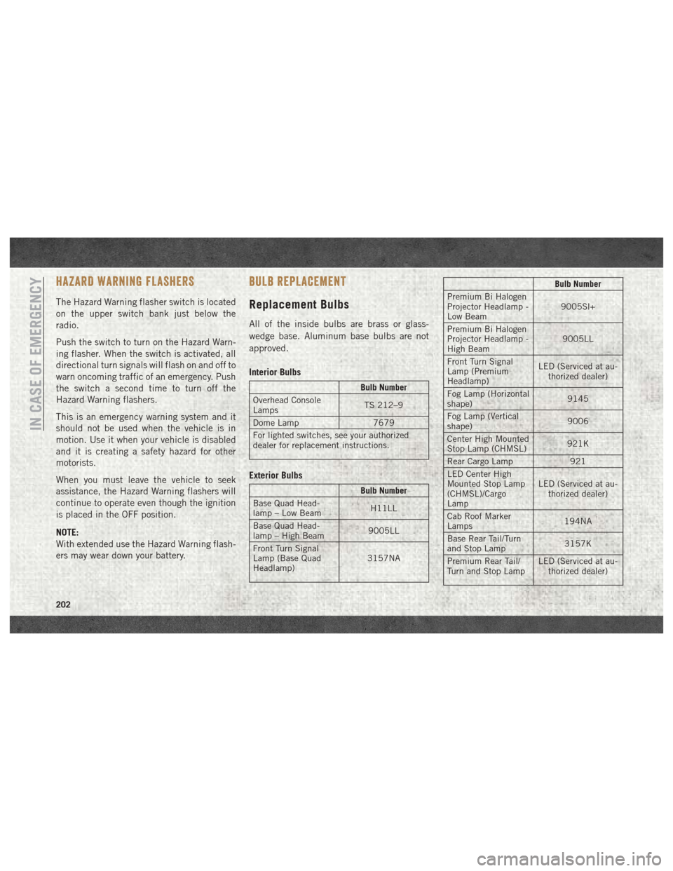
BULB REPLACEMENT
Replacement Bulbs
All of the inside bulbs are brass or glass-
wedge base. Aluminum base bulbs are not
approved.
Interior Bulbs
Bulb Number
Overhead Console
Lamps TS 212–9
Dome Lamp 7679
For lighted switches, see your authorized
dealer for replacement instructions.
Exterior Bulbs
Bulb Number
Base Quad Head-
lamp – Low Beam H11LL
Base Quad Head-
lamp – High Beam 9005LL
Front Turn Signal
Lamp (Base Quad
Headlamp) 3157NA
Bulb Number
Premium Bi Halogen
Projector Headlamp -
Low Beam 9005Sl+
Premium Bi Halogen
Projector Headlamp -
High Beam 9005LL
Front Turn Signal
Lamp (Premium
Headlamp) LED (Serviced at au-
thorized dealer)
Fog Lamp (Horizontal
shape) 9145
Fog Lamp (Vertical
shape) 9006
Center High Mounted
Stop Lamp (CHMSL) 921K
Rear Cargo Lamp 921
LED Center High
Mounted Stop Lamp
(CHMSL)/Cargo
Lamp LED (Serviced at au-
thorized dealer)
Cab Roof Marker
Lamps 194NA
Base Rear Tail/Turn
and Stop Lamp 3157K
Premium Rear Tail/
Turn and Stop Lamp LED (Serviced at au-
thorized dealer)
IN CASE OF EMERGENCY
202
Page 205 of 372

Bulb Number
Premium Backup
Lamp 7440/W21W
Rear Lamp Bar ID
Marker Lamp 194
Side Marker Lamps
(Dual Rear Wheels) 194
Backup Lamp 921
Rear License Plate
Lamp 194
FUSES
WARNING!
• When replacing a blown fuse, always use
an appropriate replacement fuse with
the same amp rating as the original fuse.
Never replace a fuse with another fuse of
WARNING!
higher amp rating. Never replace a
blown fuse with metal wires or any other
material. Do not place a fuse inside a
circuit breaker cavity or vice versa. Fail-
ure to use proper fuses may result in
serious personal injury, fire and/or prop-
erty damage.
• Before replacing a fuse, make sure that
the ignition is off and that all the other
services are switched off and/or disen-
gaged.
• If the replaced fuse blows again, contact
an authorized dealer.
• If a general protection fuse for safety
systems (air bag system, braking sys-
tem), power unit systems (engine sys-
tem, transmission system) or steering
WARNING!
system blows, contact an authorized
dealer.
Power Distribution Center
The Power Distribution Center is located in
the engine compartment near the battery.
This center contains cartridge fuses, micro
fuses, relays, and circuit breakers. A descrip-
tion of each fuse and component may be
stamped on the inside cover, otherwise the
cavity number of each fuse is stamped on the
inside cover that corresponds to the following
chart.
Cavity Cartridge Fuse Micro Fuse Description
F01 80 Amp Black –Rad Fan Control Module – If Equipped
F03 60 Amp Yellow –Rad Fan – If Equipped
F05 40 Amp Green –Compressor for Air Suspension – If Equipped
F06 40 Amp Green –Antilock Brakes/Electronic Stability Control Pump
203
Page 359 of 372
Accessories..................287
Mopar ...................287
Adding Fuel ..........181, 182, 186
Additives, Fuel ................182
Adjustable Pedals ...............30
Air Bag Air Bag Operation ............106
Air Bag Warning Light .........104
Enhanced Accident Response .114, 227
Event Data Recorder (EDR) ......227
If A Deployment Occurs ........113
Knee Impact Bolsters .........107
Maintaining Your Air Bag System . .114
Transporting Pets ............133
Air Bag Light ...........76, 104, 135
Air Bag Maintenance ............114
Air Cleaner, Engine (Engine Air Cleaner Filter) ...........249, 252
Air Conditioning Filter ............48
Air Conditioning, Operating Tips ......48
Air Conditioning System ...........47
Air Filter ...................252
Air Pressure, Tires ..............265
Air Suspension ............170, 172
Alarm, Panic ..................15 Alarm (Security Alarm)
.........18, 77
Alarm System (Security Alarm) .......18
Antifreeze (Engine Coolant) ........278
Capacities ................279
Anti-Lock Warning Light ...........81
Audio Jack ..................325
Automatic Headlights ............33
Automatic High Beams ...........33
Automatic Temperature Control (ATC) . . .47
Automatic Transmission ..........156
Fluid Type .........282, 284, 286
Shifting ..............158, 160
Automatic Transmission Limp Home Mode ....................157
Axle Fluid ............282, 284, 286
Back-Up ...................179
Back-Up Camera ..............179
Battery .....................
77
Charging System Light .........77
Belts, Seat ..................134
Body Builders Guide ..............2
B-Pillar Location ..............261
Brake Fluid ..............282, 284 Brake System
Warning Light ...............76
Brake/Transmission Interlock .......156
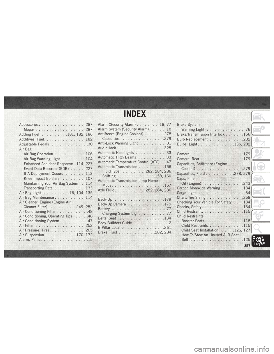
Bulb Replacement .............202
Bulbs, Light ..............136, 202
Camera ....................179
Camera, Rear ................179
Capacities, Antifreeze (Engine Coolant) ..................279
Capacities, Fluid ...........278, 279
Caps, Filler Oil (Engine) ...............243
Carbon Monoxide Warning .........134
Cargo Light ...................34
Chart, Tire Sizing ..............258
Checking Your Vehicle For Safety . . . .134
Checks, Safety ................134
Child Restraint ................115
Child Restraints Booster Seats ..............118
Child Restraints .............115
Child Seat Installation .....126, 127
How To Stow An Unused ALR Seat
Belt ....................125
INDEX
357