heater Ram 3500 2018 User Guide
[x] Cancel search | Manufacturer: RAM, Model Year: 2018, Model line: 3500, Model: Ram 3500 2018Pages: 372, PDF Size: 7.1 MB
Page 4 of 372
HOW TO USE THIS MANUAL
Essential Information
Each time direction instructions (left/right or
forwards/backwards) about the vehicle are
given, these must be intended as regarding
an occupant in the driver's seat. Special
cases not complying with this rule will be
properly specified in the text.
The figures in this User Guide are provided by
way of example only: this might imply that
some details of the image do not correspond
to the actual arrangement of your vehicle.
In addition, the User Guide has been conceived
considering vehicles with steering wheel on the
left side; it is therefore possible that on vehicles
with steering wheel on the right side, the posi-
tion or construction of some controls is not
exactly mirror-like with respect to the figure.
To identify the chapter with the information
needed you can consult the index at the end
of this User Guide.
Chapters can be rapidly identified with dedi-
cated graphic tabs, at the side of each oddpage. A few pages further there is a key for
getting to know the chapter order and the
relevant symbols in the tabs. There is anyway
a textual indication of the current chapter at
the side of each even page.
Symbols
Some vehicle components have colored la-
bels whose symbols indicate precautions to
be observed when using this component.
WARNINGS AND CAUTIONS
While reading this User Guide you will find a
series of WARNINGS to be followed to pre-
vent incorrect use of components which
could cause accidents or injuries.
There are also CAUTIONS that must be fol-
lowed to prevent against procedures that
could result in damage to your vehicle.
VAN CONVERSIONS/CAMPERS
The New Vehicle Limited Warranty does not
apply to body modifications or special equip-
ment installed by van conversion/camper
manufacturers/body builders. U.S. residents
refer to the Warranty Information book, Section
2.1.C. Canadian residents refer to the “What Is
Not Covered” section of the Warranty Informa-
tion book. Such equipment includes video
monitors, VCRs, heaters, stoves, refrigerators,
etc. For warranty coverage and service on these
items, contact the applicable manufacturer.
Operating instructions for the special equip-
ment installed by the conversion/camper
manufacturer should also be supplied with
your vehicle. If these instructions are miss-
ing, please contact your authorized dealer for
assistance in obtaining replacement docu-
ments from the applicable manufacturer.
For information on the Body Builder’s Guide
refer to www.rambodybuilder.com. This web-
site contains dimensional and technical
specifications for your vehicle. It is intended
for Second Stage Manufacturer's technical
support. For service issues, contact your au-
thorized dealer.
INTRODUCTION
2
Page 27 of 372
Each stored memory setting will have an
associated Easy Entry and Easy Exit position.
NOTE:
The Easy Entry/Exit feature is not enabled
when the vehicle is delivered from the fac-
tory. The Easy Entry/Exit feature is enabled
(or later disabled) through the programmable
features in the Uconnect system. Refer to
“Uconnect Settings” in “Multimedia” in the
Owner’s Manual for further information.
Heated Seats
On some models, the front and rear seats may
be equipped with heaters located in the seat
cushions and seat backs.
WARNING!
• Persons who are unable to feel pain tothe skin because of advanced age,
chronic illness, diabetes, spinal cord in-
jury, medication, alcohol use, exhaus-
tion or other physical condition must
exercise care when using the seat
heater. It may cause burns even at low
WARNING!
temperatures, especially if used for long
periods of time.
•
Do not place anything on the seat or
seatback that insulates against heat, such
as a blanket or cushion. This may cause
the seat heater to overheat. Sitting in a
seat that has been overheated could
cause serious burns due to the increased
surface temperature of the seat.
Front Heated Seats
The front heated seats control buttons are
located on the center instrument panel below
the climate controls.
If your vehicle is equipped with a touch-
screen, the front heated seats control buttons
are also located within the climate or controls
screen of the touchscreen.
• Press the heated seat button
once to
turn the HI setting on.
• Press the heated seat button
a second
time to turn the LO setting on.
• Press the heated seat button
a third
time to turn the heating elements off. When the HI-level setting is selected, the
heater will provide a boosted heat level dur-
ing the first four minutes of operation. Then,
the heat output will drop to the normal HI-
level. If the HI-level setting is selected, the
system will automatically switch to LO-level
after approximately 60 minutes of continu-
ous operation. At that time, the display will
change from HI to LO, indicating the change.
The LO-level setting will turn off automati-
cally after approximately 45 minutes.
NOTE:
The engine must be running for the heated
seats to operate.
Vehicles Equipped With Remote Start
On models that are equipped with remote
start, the driver’s seat can be programmed to
come on during a remote start.
If your vehicle is equipped with a touch-
screen, this feature can be programmed
through the Uconnect system. Refer to
“Uconnect Settings” in “Multimedia” in the
Owner’s Manual for further information.
If your vehicle is not equipped with a touch-
screen, this feature can be programmed
through the instrument cluster display. Refer
25
Page 28 of 372
to “Instrument Cluster Display” in “Getting
To Know Your Instrument Panel” in the Own-
er’s Manual for further information.
Rear Heated Seats
On some models, the two outboard seats are
equipped with heated seats. The heated seat
switches for these seats are located on the
rear of the center console.
There are two heated seat switches that allow
the rear passengers to operate the seats in-
dependently. You can choose from HI, LO or
OFF heat settings. Amber indicator lights in
each switch indicate the level of heat in use.
Two indicator lights will illuminate for HI, one
for LO and none for OFF.Push the switch once
to select HI-level heat-
ing. Push the switch a
second time to select
LO-level heating. Push
the switch a third time
to shut the heating el-
ements OFF. NOTE:
• Once a heat setting is selected, heat will be
felt within two to five minutes.
• The engine must be running for the heated seats to operate.
When the HI-level setting is selected, the
heater will provide a boosted heat level dur-
ing the first four minutes of operation. Then,
the heat output will drop to the normal HI-
level. If the HI-level setting is selected, the
system will automatically switch to LO-level
after approximately 60 minutes of continu-
ous operation. At that time, the number of
illuminated LEDs changes from two to one,
indicating the change. The LO-level setting
will turn OFF automatically after approxi-
mately 45 minutes.
Ventilated Seats — If Equipped
Located in the seat cushion are small fans
that draw the air from the passenger compart-
ment and move air through fine perforations
in the seat cover to help keep the driver and
front passenger cooler in higher ambient
temperatures. The fans operate at two
speeds, HI and LO. The front ventilated seats control buttons are
located on the center instrument panel below
the climate controls.
If your vehicle is equipped with a touch-
screen, the front ventilated seats control but-
tons are also located within the climate or
controls screen of the touchscreen.
• Press the ventilated seat button
once to
choose HI.
• Press the ventilated seat button
a
second time to choose LO.
• Press the ventilated seat button
a third
time to turn the ventilated seat OFF.
NOTE:
The engine must be running for the venti-
lated seats to operate.
Vehicles Equipped With Remote Start
On models that are equipped with remote
start, the ventilated seats can be pro-
grammed to come on during a remote start.
GETTING TO KNOW YOUR VEHICLE
26
Page 32 of 372
This feature can be programmed through the
Uconnect system. Refer to “Uconnect Set-
tings” in “Multimedia” in the Owner’s
Manual for further information.
WARNING!
• Persons who are unable to feel pain tothe skin because of advanced age,
chronic illness, diabetes, spinal cord in-
jury, medication, alcohol use, exhaus-
tion, or other physical conditions must
exercise care when using the steering
wheel heater. It may cause burns even at
low temperatures, especially if used for
long periods.
• Do not place anything on the steering
wheel that insulates against heat, such
as a blanket or steering wheel covers of
any type and material. This may cause
the steering wheel heater to overheat.
DRIVER ADJUSTABLE PEDALS — IF
EQUIPPED
The adjustable pedals system is designed to
allow a greater range of driver comfort for
steering wheel tilt and seat position. This
feature allows the brake, accelerator, and
clutch pedals (if equipped) to move toward or
away from the driver to provide improved
position with the steering wheel.
The adjustable pedal switch is located to the
left side of the steering column.
• The pedals can be adjusted with the igni-
tion OFF.
• The pedals cannotbe adjusted when the
vehicle is in REVERSE or when the Speed
Control System is on. The following mes-
sages will appear on vehicles equipped with
an instrument cluster display if the pedals
are attempted to be adjusted when the
system is locked out: “Adjustable Pedal
Disabled — Cruise Control Engaged” or
“Adjustable Pedal Disabled — Vehicle In
Reverse”. NOTE:
• Always adjust the pedals to a position that
allows full pedal travel.
• Further small adjustments may be neces- sary to find the best possible seat/pedal
position.
• For vehicles equipped with Driver Memory Seat, you can use your remote keyless entry
key fob or the memory switch on the driver’s
door trim panel to return the adjustable
pedals to pre-programmed positions. Refer
to “Driver Memory Seat” in “Getting To
Know Your Vehicle” for further information.
WARNING!
Do not adjust the pedals while the vehicle
is moving. You could lose control and have
an accident. Always adjust the pedals
while the vehicle is parked.
CAUTION!
Do not place any article under the adjust-
able pedals or impede its ability to move,
as it may cause damage to the pedal con-
GETTING TO KNOW YOUR VEHICLE
30
Page 50 of 372
Manual Operation Override
This system offers a full complement of
manual override features. The AUTO symbol
in the front ATC display will be turned off
when the system is being used in the manual
mode.
Operating Tips
Summer Operation
The engine cooling system must be protected
with a high-quality antifreeze coolant to pro-
vide proper corrosion protection and to pro-
tect against engine overheating. OAT coolant
(conforming to MS.90032) is recommended.
Winter Operation
To ensure the best possible heater and de-
froster performance, make sure the engine
cooling system is functioning properly and
the proper amount, type, and concentration
of coolant is used. Use of the Air Recircula-
tion mode during Winter months is not rec-
ommended, because it may cause window
fogging.
Vacation/Storage
Before you store your vehicle, or keep it out of
service (i.e., vacation) for two weeks or more,
run the air conditioning system at idle for
about five minutes, in fresh air with the
blower setting on high. This will ensure ad-
equate system lubrication to minimize the
possibility of compressor damage when the
system is started again.
Window Fogging
Vehicle windows tend to fog on the inside in
mild, rainy, and/or humid weather. To clear
the windows, select Defrost or Mix mode and
increase the front blower speed. Do not use
the Recirculation mode without A/C for long
periods, as fogging may occur.
Outside Air Intake
Make sure the air intake, located directly in
front of the windshield, is free of obstruc-
tions, such as leaves. Leaves collected in the
air intake may reduce airflow, and if they
enter the plenum, they could plug the water
drains. In Winter months, make sure the air
intake is clear of ice, slush, and snow.
Cabin Air Filter
The climate control system filters out dust
and pollen from the air. Contact an autho-
rized dealer to service your cabin air filter,
and to have it replaced when needed.
GETTING TO KNOW YOUR VEHICLE
48
Page 147 of 372
• Vehicle is not in PARK
• Vehicle speed is 1.2 MPH (1.9 km/h) orless
• Driver’s seat belt is unbuckled
• Driver’s door is ajar
• Brake Pedal is not depressed
The MESSAGE “AutoPark Engaged Shift to P
then Shift to Gear” will display in the instru-
ment cluster.
NOTE:
In some cases the ParkSense graphic will be
displayed in the instrument cluster, causing
the “AutoPark Engaged Shift to P then Shift to
Gear” to not be seen. In these cases, the
shifter must be returned to “P” to select
desired gear.
If the driver shifts into PARK while moving, the
vehicle may AutoPark.
AutoPark will engage ONLYwhen vehicle
speed is 1.2 MPH (1.9 km/h) or less.
The MESSAGE “Vehicle Speed is Too High to
Shift to P”will be displayed in the instrument
cluster if vehicle speed is above 1.2 MPH
(1.9 km/h).WARNING!
If vehicle speed is above 1.2 MPH
(1.9 km/h), the transmission will default to
NEUTRAL until the vehicle speed drops
below 1.2 MPH (1.9 km). A vehicle left in
the NEUTRAL position can roll. As an
added precaution, always apply the park-
ing brake when exiting the vehicle.
4WD LOW — If Equipped
AutoPark will be disabled when operating the
vehicle in 4WD LOW.
The MESSAGE “AutoPark Disabled” will be
displayed in the instrument cluster.
Additional customer warnings will be given
when all of these conditions are met:
• Vehicle is not in PARK
• Driver’s Door is ajar
• Vehicle is in 4WD LOW range
The MESSAGE “AutoPark Not Engaged” will
be displayed in the instrument cluster. A
warning chime will continue until you shift
the vehicle into PARK or the Driver’s Door is
closed. ALWAYS DO A VISUAL CHECK
that your vehicle
is in PARK by looking for the "P" in the
Instrument Cluster Display and near the
shifter. As an added precaution, always apply
the parking brake when exiting the vehicle.
Extreme Cold Weather
The engine block heater is a resistance heater
installed in the water jacket of the engine. It
requires a 110–115 Volt AC electrical outlet
with a grounded, three-wire extension cord.
Its use is recommended for environments
that routinely fall below -10°F (-23°C). It
should be used when the vehicle has not been
running overnight or longer periods and
should be plugged in two hours prior to start.
Its use is required for cold starts with tem-
peratures under -20°F (-28°C).
NOTE:
The engine block heater cord is a factory
installed option. If your vehicle is not
equipped, heater cords are available from
your authorized Mopar dealer.
• A 12 Volt heater built into the fuel filter housing aids in preventing fuel gelling. It is
controlled by a built-in thermostat.
145
Page 149 of 372

cally crank when the "Wait To Start" time
has elapsed. See the section "Starting Pro-
cedure Engine Manifold Air Temperature
0°F to 66°F (18° C to 19°C)" in the Diesel
Supplement for more information.
To Turn Off The Engine Using ENGINE START/
STOP Button
1. Place the gear selector in PARK, then push and release the ENGINE START/
STOP button.
2. The ignition will return to the OFF mode.
3. If the gear selector is not in PARK and the ENGINE START/STOP button is pushed
once, the instrument cluster will display a
“Vehicle Not In Park” message and the
engine will remain running. Never leave a
vehicle out of the PARK position, or it
could roll.
4. If the gear selector is in NEUTRAL, and the vehicle speed below 5 mph (8 km/h),
pushing the START/STOP button once will
turn the engine off. The ignition will re-
main in the ACC mode.
5.
If the vehicle speed is above 5 mph (8 km/h),
the ENGINE START/STOP button must be held for two seconds (or three short pushes
in a row) to turn the engine off. The ignition
will remain in the ACC mode (NOT the OFF
mode) if the engine is turned off when the
transmission is not in PARK.
NOTE:
If the ignition is left in the ACC or ON/RUN
(engine not running) mode and the transmis-
sion is in PARK, the system will automatically
time out after 30 minutes of inactivity and
the ignition return to the OFF mode.
ENGINE START/STOP Button Functions — With
Driver’s Foot OFF The Brake Pedal (In PARK Or
NEUTRAL Position)
The ENGINE START/STOP button operates
similar to an ignition switch. It has three
positions, OFF, ACC, RUN. To change the
ignition switch positions without starting the
vehicle and use the accessories follow these
steps:
1. Starting with the ignition in the OFF
position:
2. Push the ENGINE START/STOP button once to change the ignition to the ACC
position. 3. Push the ENGINE START/STOP button a
second time to change the ignition to the
RUN position.
4. Push the ENGINE START/STOP button a third time to return the ignition to the OFF
position.
Keyless Enter-N-Go Starting Procedure —
Engine Manifold Air Temperature 0° F To
66° F (–18° C to 19° C)
NOTE:
The temperature displayed in the instrument
cluster does not necessarily reflect the en-
gine manifold air temperature. Refer to “In-
strument Cluster Display” in “Getting To
Know Your Instrument Panel” for further in-
formation. When engine temperatures fall
below 66°F (19°C) the “Wait To Start Light”
will remain on indicating the intake manifold
heater system is active.
Follow the steps in the “Normal Starting”
procedure except:
1. Pushing the engine start button with thedriver’s foot on the brake will move the
147
Page 150 of 372
ignition from OFF or ACC to RUN, and will
illuminate the "Wait To Start" telltale. The
engine will not immediately crank, this is
normal operation.
2. The “Wait To Start" telltale will remain on for a period of time that varies depending
on the engine temperature.
3. While the "Wait to Start" telltale is on, the instrument cluster will additionally dis-
play a gauge or bar whose initial length
represents the full "Wait to Start" time
period. Its length will decrease until it
disappears when the "Wait to Start" time
has elapsed.
CAUTION!
If the “Water in Fuel Indicator Light” re-
mains on, DO NOT START engine before
you drain the water from the fuel filters to
avoid engine damage. Refer to “Draining
Fuel/Water Separator Filter” in “Dealer
Service” under “Servicing And Mainte-
nance” for further information. 4. After the engine “Wait To Start” telltale
goes off, the engine will automatically
crank.
CAUTION!
Do not crank engine for more than 15 sec-
onds at a time or starter motor damage
may result. Turn the ignition switch to the
OFF position and wait at least two minutes
for the starter to cool before repeating start
procedure.
5. After engine start-up, check to see that there is oil pressure.
6. Allow the engine to idle about three min- utes until the manifold heaters have com-
pleted the post-heat cycle.
7. Release the parking brake and drive.
NOTE:
• Engine idle speed will automatically in- crease to 1,000 RPM and engage the Vari-
able Geometry Turbocharger at low coolant
temperatures to improve engine warm-up. • The engine may not automatically crank
after the engine "Wait To Start" telltale goes
off if a door or the hood is ajar.
• If the engine stalls, or if the ignition switch is left ON for more than two minutes after
the “Wait To Start Light” goes out, reset the
grid heaters by turning the ignition switch
to the OFF position for at least five seconds
and then back ON. Repeat steps 1 through
7 of “Keyless Enter-N-Go Starting Proce-
dure – Engine Manifold Air Temperature
Below 66° F (19° C).”
Extreme Cold Weather
The Cummins diesel engine is equipped with
several features designed to assist cold
weather starting and operation:
• The engine block heater is a resistance
heater installed in the water jacket of the
engine just above and behind the oil filter.
It requires a 110–115 Volt AC electrical
outlet with a grounded, three-wire exten-
sion cord.STARTING AND OPERATING
148
Page 151 of 372
NOTE:
The engine block heater cord is a factory
installed option. If your vehicle is not
equipped, heater cords are available from
your authorized Mopar dealer.
• A 12 Volt heater built into the fuel filterhousings aid in preventing fuel gelling. It is
controlled by a built-in thermostat.
• A heated intake air system both improves engine starting and reduces the amount of
white smoke generated by a warming
engine.NORMAL OPERATION — 3.0L DIESEL
ENGINE
Observe the following when the diesel engine
is operating.
• All message center lights are off.
• Malfunction Indicator Light (MIL) is off.
• Engine Oil Pressure telltale is not illumi-nated.
• Voltmeter operation:
The voltmeter may show a gauge fluctuation
at various engine temperatures. This is
caused by the glow plug heating system. The
number of cycles and the length of the cy-
cling operation is controlled by the engine
control module. Glow plug heater operation
can run for several minutes, once the heater
operation is complete the voltmeter needle
will stabilize.
Cold Weather Precautions
Operation in ambient temperature below
32°F (0°C) may require special consider-
ations. The following charts suggest these
options:
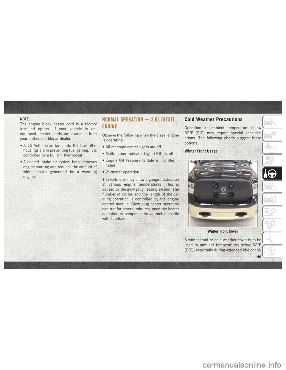
Winter Front Usage
A winter front or cold weather cover is to be
used in ambient temperatures below 32°F
(0°C), especially during extended idle condi-
Winter Front Cover
149
Page 153 of 372
NORMAL OPERATION — 6.7L DIESEL
ENGINE
Observe the following when the engine is
operating.
• All message center lights are off.
• Malfunction Indicator Light (MIL) is off.
• Engine oil pressure is above 10 psi(69 kPa) at idle.
• Voltmeter operation:
The voltmeter may show a gauge fluctuation
at various engine temperatures. This cycling
operation is caused by the post-heat cycle of
the intake manifold heater system. The num-
ber of cycles and the length of the cycling
operation is controlled by the engine control
module. Post-heat operation can run for sev-
eral minutes, and then the electrical system
and voltmeter needle will stabilize.
The cycling action will cause temporary dim-
ming of the headlamps, interior lamps, and
also a noticeable reduction in blower motor
speed.
Cold Weather Precautions
Operation in ambient temperature below
32°F (0°C) may require special consider-
ations. The following charts suggest these
options:
Winter Front Cover Usage
A winter front or cold weather cover is to be
used in ambient temperatures below 32°F
(0°C), especially during extended idle condi-
tions. This cover is equipped with four flaps
for managing total grille opening in varying
ambient temperatures. If a winter front or
cold weather cover is to be used the flaps
should be left in the full open position to
allow air flow to the charge air cooler and
automatic transmission oil cooler. When am-
bient temperatures drop below 0°F (-17°C)
the four flaps need to be closed. A suitable
cold weather cover is available from your
Mopar dealer.
Engine Idling
Avoid prolonged idling, long periods of idling
may be harmful to your engine because com-
bustion chamber temperatures can drop so low that the fuel may not burn completely.
Incomplete combustion allows carbon and
varnish to form on piston rings, engine valves,
and injector nozzles. Also, the unburned fuel
can enter the crankcase, diluting the oil and
causing rapid wear to the engine.
If the engine is allowed to idle or the truck is
driven on low engine speed drive cycles for
more than 2 hours, the system will automati-
cally enter an emissions operating mode that
will increase the engine idle speed to
900 RPM (1050 RPM for Chassis Cab).
While in this mode, which is designed to help
maintain the diesel particulate filter, the en-
gine idle speed will return to normal when the
brake pedal is applied. A small change in
engine tone or a slight change in engine
performance while accelerating may also be
noticeable at speeds below 20 mph
(32 kmh). This operating mode may last for
up to an hour of idle time, or around 20 min-
utes of driving time.
Your truck may have been ordered with an
optional voltage monitoring idle up feature. If
a load is placed on the electrical system while
the truck is in park, this feature will attempt
151