tailgate Ram 3500 2018 User Guide
[x] Cancel search | Manufacturer: RAM, Model Year: 2018, Model line: 3500, Model: Ram 3500 2018Pages: 372, PDF Size: 7.1 MB
Page 12 of 372
Wind Buffeting................50
Pinch Protect Feature ............50
Venting Sunroof — Express .........50
HOOD......................50
To Open The Hood ..............50
To Close The Hood ..............51
UNIVERSAL GARAGE DOOR OPENER
(HOMELINK)..................51
Before You Begin Programming
HomeLink....................51
Erasing All The HomeLink Channels ....52
Identifying Whether You Have A Rolling
Code Or Non-Rolling Code Device .....52Programming HomeLink To A Garage Door
Opener
.....................52
Programming HomeLink To A Miscellaneous
Device ......................54
Reprogramming A Single HomeLink
Button ......................54
General Information .............54
INTERNAL EQUIPMENT ...........55
Electrical Power Outlets ...........55
Power Inverter — If Equipped .......56
PICKUP BOX..................57
Cargo Camera — If Equipped .......58
RAMBOX — IF EQUIPPED.........59
RamBox Integrated Box Side Storage
Bins.......................59
Locking And Unlocking RamBox ......60
RamBox Safety Warning ...........60
Bed Extender — If Equipped ........61
Bed Rail Tie-Down System .........62
EASY-OFF TAILGATE.............63
Removing The Tailgate ............63
Locking Tailgate ................63
TRI-FOLD TONNEAU COVER .........63
GETTING TO KNOW YOUR VEHICLE
10
Page 16 of 372
To remove the emergency key, slide the me-
chanical latch at the top of the key fob
sideways with your thumb and then pull the
key out with your other hand.
NOTE:
When using the emergency key to gain access
to your vehicle, be aware that the security
alarm may be triggered. Insert the key into
the ignition and place the ignition in the
ON/RUN mode to disarm the security system.
This Keyless Push Button Ignition key fob
allows the driver to operate the ignition
switch with the push of a button, as long as
the key fob is in the passenger compartment.
The Keyless Push Button Ignition has four
operating positions, three of which are la-
beled and will illuminate when in position.
The three positions are OFF, ACC, and ON/
RUN. The fourth position is START, during
start RUN will illuminate. It also contains the
key fob and an emergency key, which stores
in the rear of the key fob.The emergency key allows for entry into the
vehicle should the battery in the vehicle or
the key fob go dead. You can keep the emer-
gency key with you when valet parking.
To remove the emergency key, slide the me-
chanical latch on the backside of the key fob
sideways with your thumb and then pull the
key out with your other hand.
NOTE:
• When using the emergency key to gain
access to your vehicle, be aware that the
security alarm may be triggered. Put the
nose side (side opposite of the emergency
key) of the key fob against the ENGINE
START/STOP button and push to disarm
the security system.
• You can insert the double-sided emergency key into the door lock cylinder with either
side up. The Remote Keyless Entry system allows you
to lock or unlock all doors, tailgate, and the
RamBox (if equipped) as well as activate the
Panic Alarm from distances up to approxi-
mately 66 ft (20 m) using a key fob with
integrated key. The key fob does not need to
be pointed at the vehicle to activate the
system. Push and release the lock button on
the key fob to lock all doors, the tailgate and
the RamBox (if equipped). The turn signal
lights will flash and the horn will chirp to
acknowledge the signal.
NOTE:
Inserting the key fob with integrated key into
the ignition switch disables the system from
responding to any button pushes from that
key fob. Driving at speeds 5 mph (8 km/h)
and above disables the system from respond-
ing to all key fob buttons for all key fobs.
GETTING TO KNOW YOUR VEHICLE
14
Page 17 of 372
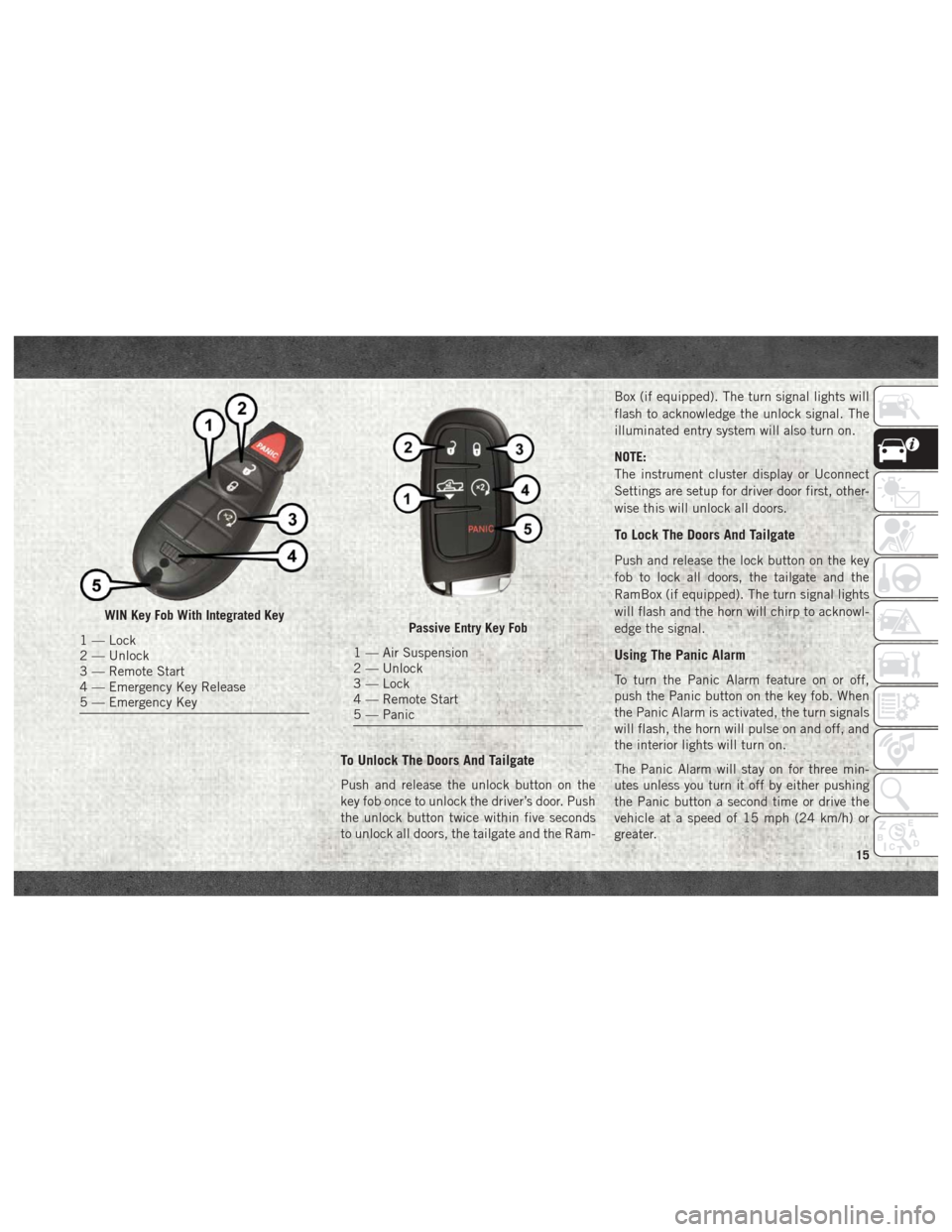
To Unlock The Doors And Tailgate
Push and release the unlock button on the
key fob once to unlock the driver’s door. Push
the unlock button twice within five seconds
to unlock all doors, the tailgate and the Ram-Box (if equipped). The turn signal lights will
flash to acknowledge the unlock signal. The
illuminated entry system will also turn on.
NOTE:
The instrument cluster display or Uconnect
Settings are setup for driver door first, other-
wise this will unlock all doors.
To Lock The Doors And Tailgate
Push and release the lock button on the key
fob to lock all doors, the tailgate and the
RamBox (if equipped). The turn signal lights
will flash and the horn will chirp to acknowl-
edge the signal.
Using The Panic Alarm
To turn the Panic Alarm feature on or off,
push the Panic button on the key fob. When
the Panic Alarm is activated, the turn signals
will flash, the horn will pulse on and off, and
the interior lights will turn on.
The Panic Alarm will stay on for three min-
utes unless you turn it off by either pushing
the Panic button a second time or drive the
vehicle at a speed of 15 mph (24 km/h) or
greater.
WIN Key Fob With Integrated Key
1 — Lock
2 — Unlock
3 — Remote Start
4 — Emergency Key Release
5 — Emergency KeyPassive Entry Key Fob
1 — Air Suspension
2 — Unlock
3 — Lock
4 — Remote Start
5 — Panic
15
Page 62 of 372
CAUTION!
Leaving the lid open for extended periods
of time could cause the vehicle battery to
discharge. If the lid is required to stay
open for extended periods of time, it is
recommended that the bin lights be
turned off manually using the on/off
switch.
The interior of the RamBox will automatically
illuminate when the lid is opened. In addition
to the automatic illumination switch, there is
a manual on/off switch located at the rear of
each storage bin. Pushing the switch once
will turn off the bin lights, pushing the switch
again will turn the lights back on.
Cargo bins feature two removable drain plugs
(to allow water to drain from bins). To remove
plug, pull up on the edge. To install push plug
downward into drain hole.
NOTE:
Provisions are provided in the bins for cargo
dividers and shelf supports. These accesso-
ries (in addition to other RamBox accesso-
ries) are available from Mopar.
Locking And Unlocking RamBox
Push and release the lock or unlock button on
the key fob to lock and unlock all doors, the
tailgate and the RamBox (if equipped). Refer
to “Keys” in “Getting To Know Your Vehicle”
in the Owner’s Manual for further details. The
RamBox storage bins can be locked using the
vehicle key. To lock and unlock the storage
bin, insert the key into the keyhole on the
push button and turn clockwise to lock or
counterclockwise to unlock. Always return
the key to the upright (vertical) position be-
fore removing the key from the push button.
CAUTION!
• Ensure cargo bin lids are closed and latched before moving or driving vehicle.
• Loads applied to the top of the bin lid
should be minimized to prevent damage
to the lid and latching/hinging mecha-
nisms.
• Damage to the RamBox bin may occur
due to heavy/sharp objects placed in bin
that shift due to vehicle motion. In order
to minimize potential for damage, se-
CAUTION!
cure all cargo to prevent movement and
protect inside surfaces of bin from
heavy/sharp objects with appropriate
padding.
RamBox Safety Warning
Carefully follow these warnings to help pre-
vent personal injury or damage to your
vehicle:
WARNING!
• Always close the storage bin coverswhen your vehicle is unattended.
• Do not allow children to have access to
the storage bins. Once in the storage
bin, young children may not be able to
escape. If trapped in the storage bin,
children can die from suffocation or heat
stroke.
• In an accident, serious injury could re-
sult if the storage bin covers are not
properly latched.
GETTING TO KNOW YOUR VEHICLE
60
Page 64 of 372
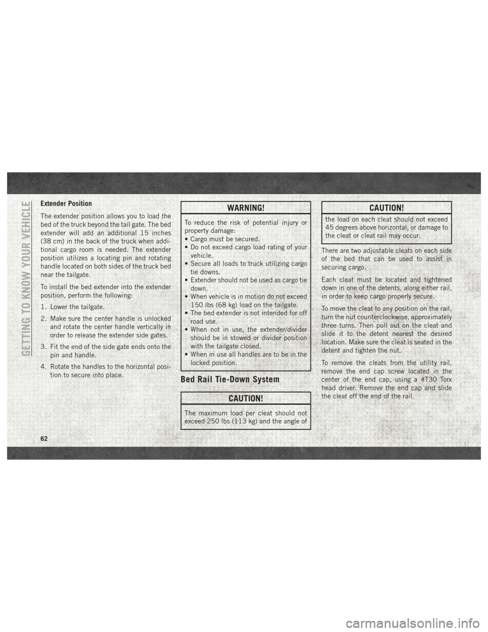
Extender Position
The extender position allows you to load the
bed of the truck beyond the tail gate. The bed
extender will add an additional 15 inches
(38 cm) in the back of the truck when addi-
tional cargo room is needed. The extender
position utilizes a locating pin and rotating
handle located on both sides of the truck bed
near the tailgate.
To install the bed extender into the extender
position, perform the following:
1. Lower the tailgate.
2. Make sure the center handle is unlockedand rotate the center handle vertically in
order to release the extender side gates.
3. Fit the end of the side gate ends onto the pin and handle.
4. Rotate the handles to the horizontal posi- tion to secure into place.WARNING!
To reduce the risk of potential injury or
property damage:
• Cargo must be secured.
• Do not exceed cargo load rating of yourvehicle.
• Secure all loads to truck utilizing cargo
tie downs.
• Extender should not be used as cargo tie
down.
• When vehicle is in motion do not exceed
150 lbs (68 kg) load on the tailgate.
• The bed extender is not intended for off
road use.
• When not in use, the extender/divider
should be in stowed or divider position
with the tailgate closed.
• When in use all handles are to be in the
locked position.
Bed Rail Tie-Down System
CAUTION!
The maximum load per cleat should not
exceed 250 lbs (113 kg) and the angle of
CAUTION!
the load on each cleat should not exceed
45 degrees above horizontal, or damage to
the cleat or cleat rail may occur.
There are two adjustable cleats on each side
of the bed that can be used to assist in
securing cargo.
Each cleat must be located and tightened
down in one of the detents, along either rail,
in order to keep cargo properly secure.
To move the cleat to any position on the rail,
turn the nut counterclockwise, approximately
three turns. Then pull out on the cleat and
slide it to the detent nearest the desired
location. Make sure the cleat is seated in the
detent and tighten the nut.
To remove the cleats from the utility rail,
remove the end cap screw located in the
center of the end cap, using a #T30 Torx
head driver. Remove the end cap and slide
the cleat off the end of the rail.
GETTING TO KNOW YOUR VEHICLE
62
Page 65 of 372
EASY-OFF TAILGATE
To simplify mounting of a camper unit with an
overhang, the tailgate can be removed.
NOTE:
If your vehicle is equipped with a rear camera
or Remote Keyless Entry, the electrical con-
nector must be disconnected prior to remov-
ing the tailgate.
Removing The Tailgate
1. Disconnect the wiring harness for the rearcamera or Remote Keyless Entry (if
equipped).
2. Unlatch the tailgate and remove the sup- port cables by releasing the lock tang from
the pivot. 3. Raise the right side of the tailgate until
the right side pivot clears the hanger
bracket.
4. Slide the entire tailgate to the right to free the left side pivot.
5. Remove the tailgate from the vehicle.
NOTE:
Do not carry the tailgate loose in the truck
pickup box.Locking Tailgate
The lock is located next to the tailgate
handle. The tailgate can be locked using the
vehicle key or by locking the truck with the
key fob if equipped with remote keyless entry.
TRI-FOLD TONNEAU COVER
The Tonneau Cover can be removed and rein-
stalled by using the locking clamps located
underneath the Tonneau Cover. Refer to the
Owner’s Manual for further information.
NOTE:
Be sure that the Tonneau Cover is secured
before driving.
63
Page 181 of 372
PARKSENSE FRONT AND REAR PARK
ASSIST — IF EQUIPPED
The ParkSense Park Assist system provides
visual and audible indications of the distance
between the rear and/or front fascia and a
detected obstacle when backing up or moving
forward, e.g. during a parking maneuver. Re-
fer to “ParkSense System Usage Precau-
tions” in the Owner’s Manual for limitations
of this system and recommendations.
ParkSense will retain the last system state
(enabled or disabled) from the last ignition
cycle when the ignition is changed to the
ON/RUN position.
ParkSense can be active only when the gear
selector is in REVERSE or DRIVE. If
ParkSense is enabled at one of these gear
selector positions, the system will remain
active until the vehicle speed is increased to
approximately 7 mph (11 km/h) or above. A
warning will appear in the instrument cluster
display indicating the vehicle is aboveParkSense operating speed. The system will
become active again if the vehicle speed is
decreased to speeds less than approximately
6 mph (9 km/h).
Cleaning The ParkSense System
Clean the ParkSense sensors with water, car
wash soap and a soft cloth. Do not use rough
or hard cloths. Do not scratch or poke the
sensors. Otherwise, you could damage the
sensors.
PARKVIEW REAR BACK UP CAMERA —
IF EQUIPPED
Your vehicle may be equipped with the
ParkView Rear Back Up Camera that allows
you to see a image of the rear surroundings of
your vehicle whenever the gear selector is put
into REVERSE or whenever it is initiated
through the "Backup Camera" button in the
"Controls" menu. Whenever the gear selector
is put into REVERSE, the image will be dis-
played in the rearview mirror display (if
equipped) or Uconnect screen (if equipped)along with a caution note to “check entire
surroundings” across the top of the screen.
After five seconds this note will disappear.
The ParkView Camera is located to the left of
the tailgate handle.
When the vehicle is shifted out of REVERSE
(with Camera delay turned off), the rear Cam-
era mode is exited and the navigation or audio
screen appears again.
When the vehicle is shifted out of REVERSE
(with Camera delay turned on), the rear Cam-
era image will be displayed for up to 10 sec-
onds after shifting out of REVERSE unless
the forward vehicle speed exceeds 8 mph
(13 km/h), the transmission is shifted into
PARK or the ignition is switched to the OFF
position.
Whenever the Rear View Camera image is
activated through the "Backup Camera" but-
ton in the "Controls" menu, a display timer for
the image is initiated. The image will con-
tinue to be displayed until the display timer
exceeds 10 seconds and the vehicle speed is
above 8 mph (13 km/h) or the touchscreen
button "X" to disable display of the Rear View
Camera image is pressed.
179
Page 211 of 372
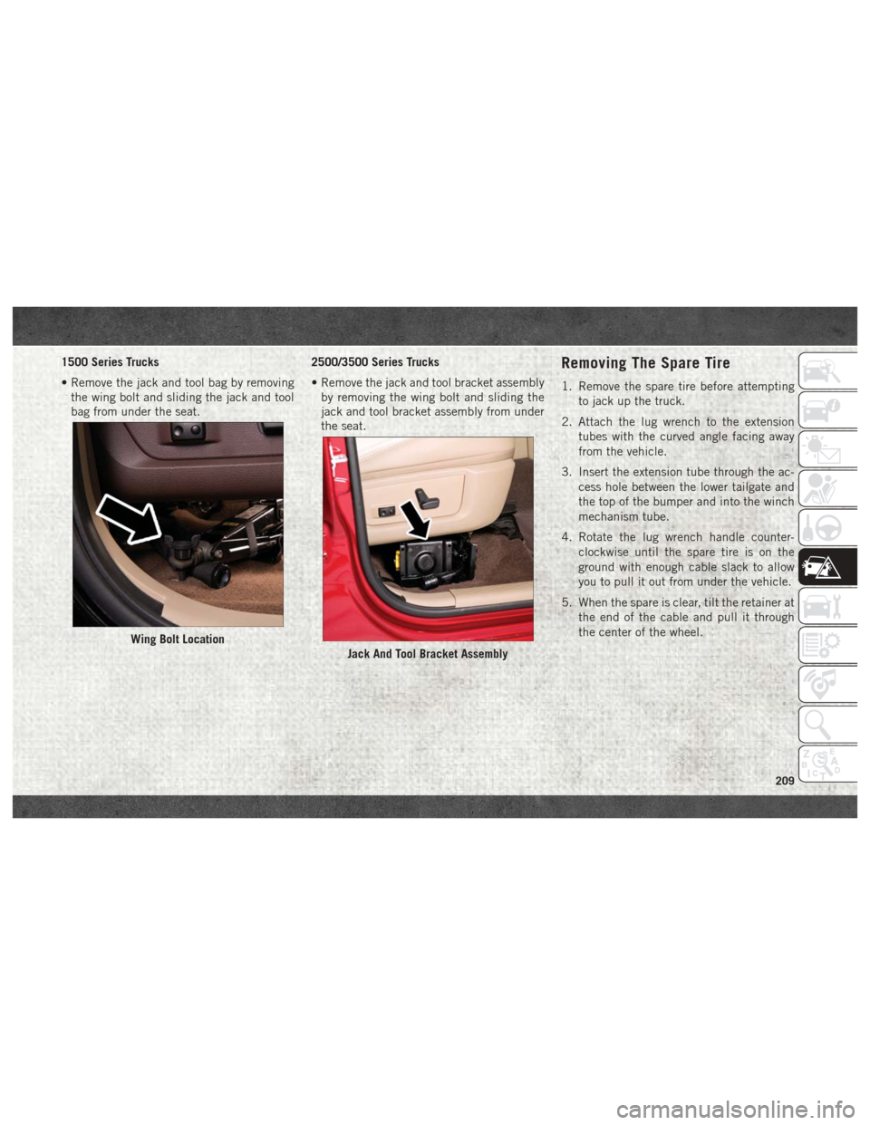
1500 Series Trucks
• Remove the jack and tool bag by removingthe wing bolt and sliding the jack and tool
bag from under the seat. 2500/3500 Series Trucks
• Remove the jack and tool bracket assembly
by removing the wing bolt and sliding the
jack and tool bracket assembly from under
the seat.Removing The Spare Tire
1. Remove the spare tire before attempting
to jack up the truck.
2. Attach the lug wrench to the extension tubes with the curved angle facing away
from the vehicle.
3. Insert the extension tube through the ac- cess hole between the lower tailgate and
the top of the bumper and into the winch
mechanism tube.
4. Rotate the lug wrench handle counter- clockwise until the spare tire is on the
ground with enough cable slack to allow
you to pull it out from under the vehicle.
5. When the spare is clear, tilt the retainer at the end of the cable and pull it through
the center of the wheel.
Wing Bolt Location
Jack And Tool Bracket Assembly
209
Page 364 of 372
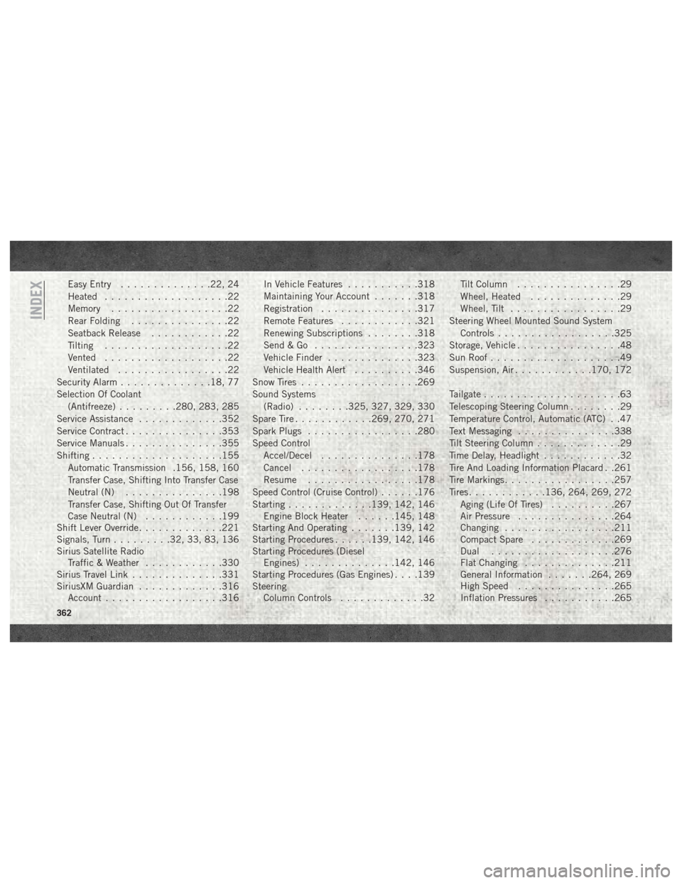
Easy Entry..............22, 24
Heated ...................22
Memory ..................22
Rear Folding ...............22
Seatback Release ............22
Tilting ...................22
Vented ...................22
Ventilated .................22
Security Alarm ..............18, 77
Selection Of Coolant (Antifreeze) .........280, 283, 285
Service Assistance .............352
Service Contract ...............353
Service Manuals ...............355
Shifting ....................155
Automatic Transmission .156, 158, 160
Transfer Case, Shifting Into Transfer Case
Neutral (N) ...............198
Transfer Case, Shifting Out Of Transfer
Case Neutral (N) ............199
Shift Lever Override .............221
Signals, Turn .........32, 33, 83, 136
Sirius Satellite Radio Traffic & Weather ............330
Sirius Travel Link ..............331
SiriusXM Guardian .............316
Account ..................316 In Vehicle Features
...........318
Maintaining Your Account .......318
Registration ...............317
Remote Features ............321
Renewing Subscriptions ........318
Send&Go ................323
Vehicle Finder ..............323
Vehicle Health Alert ..........346
Snow Tires ..................269
Sound Systems (Radio) ........325, 327, 329, 330
Spare Tire ............269, 270, 271
Spark Plugs .................280
Speed Control Accel/Decel .............. .178
Cancel ..................178
Resume .................178
Speed
Control (Cruise Control) ......176
Starting .............139, 142, 146
Engine Block Heater ......145, 148
Starting And Operating .......139, 142
Starting Procedures ......139, 142, 146
Starting Procedures (Diesel Engines) ..............142, 146
Starting Procedures (Gas Engines) . . . .139
Steering Column Controls .............32 Tilt Column
................29
Wheel, Heated ..............29
Wheel, Tilt .................29
Steering Wheel Mounted Sound System Controls ..................325
Storage, Vehicle ................48
Sun Roof ....................49
Suspension, Air ............170, 172
Tailgate .....................63
Telescoping Steering Column ........29
Temperature Control, Automatic (ATC) . .47
Text Messaging ...............338
Tilt Steering Column .............29
Time Delay, Headlight ............32
Tire And Loading Information Placard . .261
Tire Markings .................257
Tires ............136, 264, 269, 272
Aging (Life Of Tires) ..........267
Air Pressure ...............264
Changing .................211
Compact Spare .............269
Dual ...................276
Flat Changing ..............211
General Information .......264, 269
High Speed ...............265
Inflation Pressures ...........265
INDEX
362