turn signal Ram 3500 2018 User Guide
[x] Cancel search | Manufacturer: RAM, Model Year: 2018, Model line: 3500, Model: Ram 3500 2018Pages: 372, PDF Size: 7.1 MB
Page 11 of 372
GETTING TO KNOW YOUR VEHICLE
VEHICLE USER GUIDE — IF EQUIPPED .11
KEYS......................13
Key Fobs ....................13
IGNITION SWITCH ..............17
Wireless Ignition Node (WIN) — If
Equipped....................17
Keyless Push Button Ignition — If
Equipped ....................17
REMOTE START — IF EQUIPPED .....17
To Enter Remote Start Mode........17
To Exit Remote Start Mode Without
Driving The Vehicle .............18
To Exit Remote Start Mode And Drive
The Vehicle ...................18
General Information .............18
VEHICLE SECURITY ALARM ........18
To Arm The System..............18
To Disarm The System ............19
DOORS.....................19
Keyless Enter-N-Go — Passive Entry . . .19
SEATS .....................22
Driver Memory Seat — If Equipped ....22
Heated Seats ..................25
HEAD RESTRAINTS ..............27
Front Head Restraint Adjustment .....27
Rear Head Restraint Adjustment ......28
Front Head Restraint Removal .......28
Rear Head Restraint Removal ........28
STEERING WHEEL..............29
Tilt Steering Column .............29
Heated Steering Wheel — If Equipped . .29
DRIVER ADJUSTABLE PEDALS — IF
EQUIPPED ...................30
MIRRORS ...................31
Power Folding Outside Mirrors For Standard
And Trailer Tow — If Equipped .......31
EXTERIOR LIGHTS..............32
Headlight Switch...............32
Headlights ...................32
Multifunction Lever .............32
High/Low Beam Switch ...........32Automatic High Beam Headlamp Control —
If Equipped
..................33
Automatic Headlights — If Equipped . .33
Parking Lights And Panel Lights ......33
Turn Signals ..................33
Lane Change Assist — If Equipped ....34
Cargo Light With Bed Lights —
If Equipped ..................34
WINDSHIELD WIPERS AND WASHERS .35
Windshield Wipers ..............35
CLIMATE CONTROLS .............36
Manual Climate Controls With A
Touchscreen..................36
Automatic Climate Controls With A
Touchscreen ..................41
Climate Control Functions ..........46
Automatic Temperature Control (ATC) —
If Equipped ...................47
Operating Tips .................48
POWER SUNROOF — IF EQUIPPED ....49
Opening Sunroof...............49
Closing Sunroof ................49
GETTING TO KNOW YOUR VEHICLE
9
Page 16 of 372
To remove the emergency key, slide the me-
chanical latch at the top of the key fob
sideways with your thumb and then pull the
key out with your other hand.
NOTE:
When using the emergency key to gain access
to your vehicle, be aware that the security
alarm may be triggered. Insert the key into
the ignition and place the ignition in the
ON/RUN mode to disarm the security system.
This Keyless Push Button Ignition key fob
allows the driver to operate the ignition
switch with the push of a button, as long as
the key fob is in the passenger compartment.
The Keyless Push Button Ignition has four
operating positions, three of which are la-
beled and will illuminate when in position.
The three positions are OFF, ACC, and ON/
RUN. The fourth position is START, during
start RUN will illuminate. It also contains the
key fob and an emergency key, which stores
in the rear of the key fob.The emergency key allows for entry into the
vehicle should the battery in the vehicle or
the key fob go dead. You can keep the emer-
gency key with you when valet parking.
To remove the emergency key, slide the me-
chanical latch on the backside of the key fob
sideways with your thumb and then pull the
key out with your other hand.
NOTE:
• When using the emergency key to gain
access to your vehicle, be aware that the
security alarm may be triggered. Put the
nose side (side opposite of the emergency
key) of the key fob against the ENGINE
START/STOP button and push to disarm
the security system.
• You can insert the double-sided emergency key into the door lock cylinder with either
side up. The Remote Keyless Entry system allows you
to lock or unlock all doors, tailgate, and the
RamBox (if equipped) as well as activate the
Panic Alarm from distances up to approxi-
mately 66 ft (20 m) using a key fob with
integrated key. The key fob does not need to
be pointed at the vehicle to activate the
system. Push and release the lock button on
the key fob to lock all doors, the tailgate and
the RamBox (if equipped). The turn signal
lights will flash and the horn will chirp to
acknowledge the signal.
NOTE:
Inserting the key fob with integrated key into
the ignition switch disables the system from
responding to any button pushes from that
key fob. Driving at speeds 5 mph (8 km/h)
and above disables the system from respond-
ing to all key fob buttons for all key fobs.
GETTING TO KNOW YOUR VEHICLE
14
Page 17 of 372
To Unlock The Doors And Tailgate
Push and release the unlock button on the
key fob once to unlock the driver’s door. Push
the unlock button twice within five seconds
to unlock all doors, the tailgate and the Ram-Box (if equipped). The turn signal lights will
flash to acknowledge the unlock signal. The
illuminated entry system will also turn on.
NOTE:
The instrument cluster display or Uconnect
Settings are setup for driver door first, other-
wise this will unlock all doors.
To Lock The Doors And Tailgate
Push and release the lock button on the key
fob to lock all doors, the tailgate and the
RamBox (if equipped). The turn signal lights
will flash and the horn will chirp to acknowl-
edge the signal.
Using The Panic Alarm
To turn the Panic Alarm feature on or off,
push the Panic button on the key fob. When
the Panic Alarm is activated, the turn signals
will flash, the horn will pulse on and off, and
the interior lights will turn on.
The Panic Alarm will stay on for three min-
utes unless you turn it off by either pushing
the Panic button a second time or drive the
vehicle at a speed of 15 mph (24 km/h) or
greater.
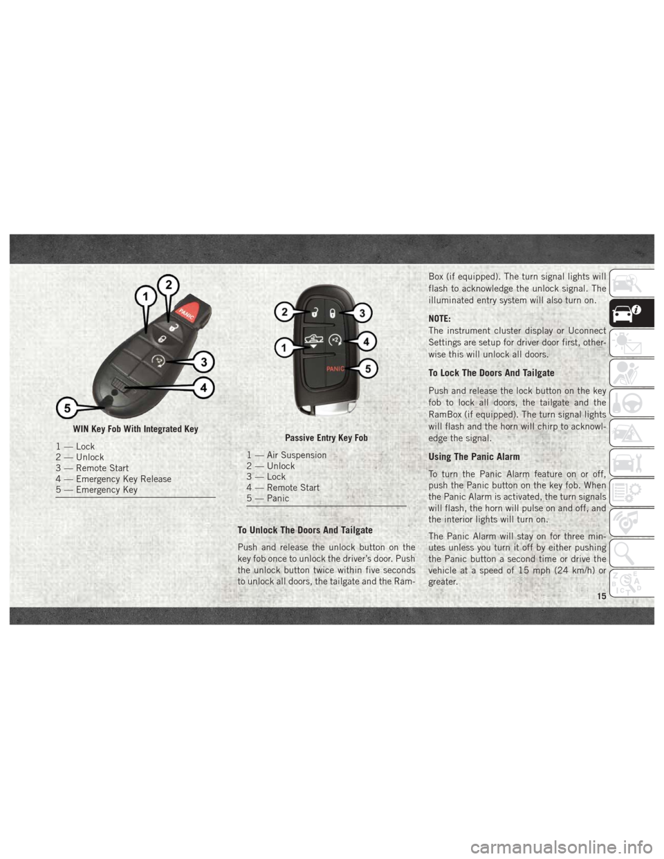
WIN Key Fob With Integrated Key
1 — Lock
2 — Unlock
3 — Remote Start
4 — Emergency Key Release
5 — Emergency KeyPassive Entry Key Fob
1 — Air Suspension
2 — Unlock
3 — Lock
4 — Remote Start
5 — Panic
15
Page 18 of 372
NOTE:
• The interior lights will turn off if you placethe ignition in the ACC or ON/RUN position
while the Panic Alarm is activated. How-
ever, the exterior lights and horn will remain
on.
• You may need to be less than 35 ft (11 m) from the vehicle when using the key fob to
turn off the Panic Alarm due to the radio
frequency noises emitted by the system.
Air Suspension (Remote Lowering Of The
Vehicle) — If Equipped
For easy entry and loading, your
vehicle can be lowered by push-
ing the key fob air suspension
lowering button two times. When
key fob lowering is requested,
the vehicle will send a series of chirps and
flashes to alert the customer that the opera-
tion has begun and will continue these alerts
until it successfully lowers. The following conditions must be met for the
vehicle to lower remotely:
• The vehicle must not already be in Entry/
Exit (Park) ride height.
• The vehicle battery must be fully charged.
• All doors must be closed.
• The key fob must be out of the vehicle.
Canceling Remote Lowering
Vehicle lowering can be cancelled at any-
time. When vehicle lowering is canceled, the
vehicle will raise up to the next defined level
and lock out the remote lowering feature until
the ignition has been cycled ON/OFF.
To cancel vehicle lowering, push the key fob
air suspension lowering button one time dur-
ing the lowering process. When vehicle low-
ering is canceled, the horn will chirp two
times and the turn signal lamps will flash four
times. Once raising is completed, the horn
will chirp one time.
NOTE:
Refer to “Air Suspension System” in “Start-
ing And Operating” for further information.
General Information
The following regulatory statement applies to
all radio frequency (RF) devices equipped in
this vehicle:
This device complies with Part 15 of the FCC
Rules and with Industry Canada license-
exempt RSS standard(s). Operation is sub-
ject to the following two conditions:
1. This device may not cause harmful inter- ference, and
2. This device must accept any interference received, including interference that may
cause undesired operation.
NOTE:
Changes or modifications not expressly ap-
proved by the party responsible for compli-
ance could void the user’s authority to oper-
ate the equipment.
GETTING TO KNOW YOUR VEHICLE
16
Page 20 of 372
• The engine can be started two consecutivetimes (two 15-minute cycles) with the key
fob. However, the ignition must be placed
in the ON/RUN position before you can
repeat the start sequence for a third cycle.
To Exit Remote Start Mode
Without Driving The Vehicle
Push and release the remote start button one
time or allow the engine to run for the entire
15-minute cycle.
NOTE:
To avoid unintentional shutdowns, the sys-
tem will disable with a one time push of the
remote start button for two seconds after
receiving a valid remote start request.
To Exit Remote Start Mode And
Drive The Vehicle
Before the end of the 15-minute cycle, push
and release the unlock button on the key fob
to unlock the doors and disarm the vehicle
security alarm system (if equipped). Then,
prior to the end of the 15-minute cycle, cycle
the ignition to the ON/RUN position.
General Information
The following regulatory statement applies to
all radio frequency (RF) devices equipped in
this vehicle:
This device complies with Part 15 of the FCC
Rules and with Industry Canada license-
exempt RSS standard(s). Operation is sub-
ject to the following two conditions:
1. This device may not cause harmful inter-
ference, and
2. This device must accept any interference received, including interference that may
cause undesired operation.
NOTE:
Changes or modifications not expressly ap-
proved by the party responsible for compli-
ance could void the user’s authority to oper-
ate the equipment.
VEHICLE SECURITY ALARM
The vehicle security alarm monitors the ve-
hicle doors and ignition for unauthorized op-
eration. When the vehicle security alarm is
activated, interior switches for door locks are disabled. The system provides both audible
and visible signals for the first three minutes.
The horn will sound, the headlights will turn
on, the park lamps and/or turn signals will
flash and vehicle security light will flash
repeatedly. For an additional 15 minutes
only, the headlights will turn on, the park
lamps and/or turn signals, and vehicle secu-
rity light will flash.
To Arm The System
Follow these steps to arm the vehicle security
alarm:
1. Remove the key from the ignition system
(refer to "Starting The Engine" in "Starting
And Operating" for further information).
• For vehicles equipped with Keyless Enter-N-Go — Ignition, make sure the
vehicle ignition system is "OFF."
• For vehicles not equipped with Keyless Enter-N-Go — Ignition, make sure the
vehicle ignition system is "OFF" and
the key is physically removed from the
ignition.
GETTING TO KNOW YOUR VEHICLE
18
Page 35 of 372
Automatic High Beam Headlamp
Control — If Equipped
The Automatic High Beam Headlamp Control
system provides increased forward lighting at
night by automating high beam control
through the use of a digital camera mounted
on the inside rearview mirror. This camera
detects vehicle specific light and automati-
cally switches from high beams to low beams
until the approaching vehicle is out of view.
NOTE:
• The Automatic High Beam Headlamp Con-trol can be turned on or off by selecting
“ON” under “Auto High Beam” within your
Uconnect settings, as well as turning the
headlight switch to the AUTO position. Re-
fer to “Uconnect Settings” in “Multimedia”
in the Owner’s Manual for further informa-
tion.
• Broken, muddy, or obstructed headlights and taillights of vehicles in the field of view
will cause headlights to remain on longer
(closer to the vehicle). Also, dirt, film, and
other obstructions on the windshield or
camera lens will cause the system to func-
tion improperly. If the windshield or Automatic High Beam
Headlamp Control mirror is replaced, the
mirror must be re-aimed to ensure proper
performance. See a local authorized dealer.
Automatic Headlights — If
Equipped
This system automatically turns the head-
lights on or off according to ambient light
levels. To turn the system on, rotate the
headlight switch counterclockwise to the
AUTO position. When the system is on, the
headlight time delay feature is also on. This
means the headlights will stay on for up to
90 seconds after you place the ignition into
the OFF position. The headlight time delay
can be programmed 0/30/60/90 seconds.
Refer to “Uconnect Settings” in “Multime-
dia” in the Owner’s Manual for further infor-
mation.
To turn the automatic system off, move the
headlight switch out of the AUTO position.
NOTE:
The engine must be running before the head-
lights will turn on in the Automatic Mode.
Parking Lights And Panel Lights
To turn on the parking lights and instrument
panel lights, rotate the headlight switch
clockwise. To turn off the parking lights,
rotate the headlight switch back to the O (off)
position.
Turn Signals
Move the multifunction lever up or down and
the arrows on each side of the instrument
cluster display will flash to show proper op-
eration of the front and rear turn signal lights.
NOTE:
If either light remains on and does not flash,
or there is a very fast flash rate, check for a
defective outside light bulb. If an indicator
fails to light when the lever is moved, it would
suggest that the indicator bulb is defective.
33
Page 36 of 372
Lane Change Assist — If
Equipped
Tap the lever up or down once, without mov-
ing beyond the detent, and the turn signal
(right or left) will flash three times then
automatically turn off.
Cargo Light With Bed Lights — If
Equipped
The cargo light and bed lights (if equipped)
are turned on by pushing the cargo lights
button located just below the headlight
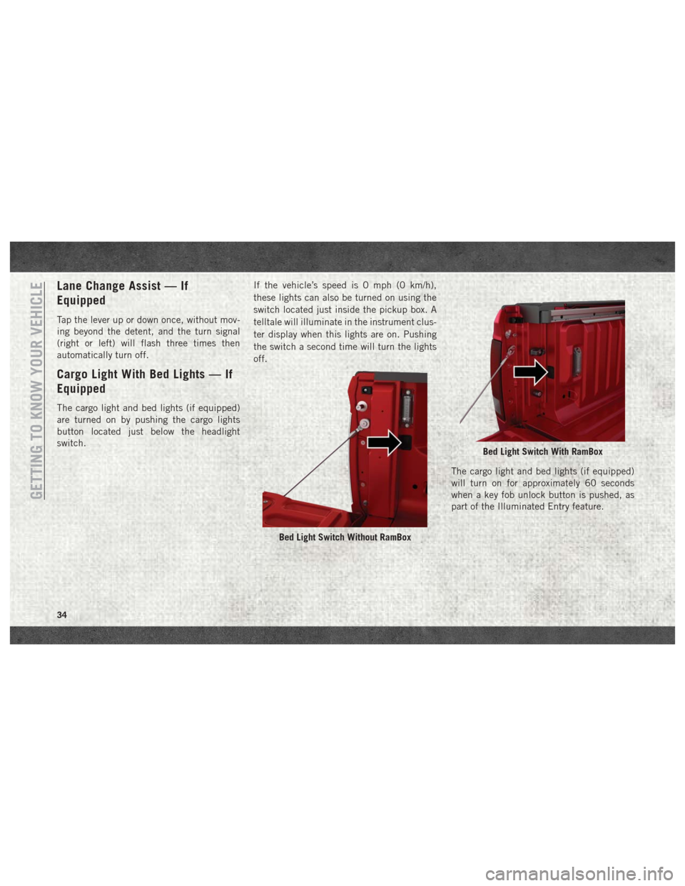
switch.If the vehicle’s speed is 0 mph (0 km/h),
these lights can also be turned on using the
switch located just inside the pickup box. A
telltale will illuminate in the instrument clus-
ter display when this lights are on. Pushing
the switch a second time will turn the lights
off.
The cargo light and bed lights (if equipped)
will turn on for approximately 60 seconds
when a key fob unlock button is pushed, as
part of the Illuminated Entry feature.
Bed Light Switch Without RamBox
Bed Light Switch With RamBox
GETTING TO KNOW YOUR VEHICLE
34
Page 85 of 372

rotate at the same speed. Low range provides
a greater gear reduction ratio to provide in-
creased torque at the wheels.
Refer to “Four-Wheel Drive Operation — If
Equipped” in “Starting And Operating” for
further information on four-wheel drive op-
eration and proper use.
— Wait To Start Light — If Equipped
The “Wait To Start” telltale will illuminate for
approximately two seconds when the ignition
is turned to the RUN position. It’s duration
may be longer based on colder operating
conditions. Vehicle will not initiate start until
telltale is no longer displayed. Refer to
“Starting The Engine” in “Starting And Op-
erating” for further information.
NOTE:
The “Wait To Start” telltale may not illumi-
nate if the intake manifold temperature is
warm enough.
— Water In Fuel Indicator Light — If
Equipped
The “Water In Fuel Indicator Light” will illu-
minate when there is water detected in the
fuel filters. If this light remains on, DO NOT
start the vehicle before you drain the water
from the fuel filters to prevent engine dam-
age. Refer to the “Draining Fuel/Water Sepa-
rator Filter” section in “Dealer Service” in
“Servicing And Maintenance” for further in-
formation.
— Low Diesel Exhaust Fluid (DEF) Indi-
cator Light — If Equipped
The Low Diesel Exhaust Fluid (DEF) Indicator
will illuminate if the vehicle is low on Diesel
Exhaust Fluid (DEF). Refer to “Starting And
Operating” for further information.
Green Indicator Lights
— Park/Headlight On Indicator Light
This indicator will illuminate when the park
lights or headlights are turned on.
— Front Fog Indicator Light — If
Equipped
This indicator will illuminate when the front
fog lights are on.
— Turn Signal Indicator Lights
When the left or right turn signal is activated,
the turn signal indicator will flash indepen-
dently and the corresponding exterior turn
signal lamps will flash. Turn signals can be
activated when the multifunction lever is
moved down (left) or up (right).
NOTE:
• A continuous chime will sound if the ve- hicle is driven more than 1 mile (1.6 km)
with either turn signal on.
• Check for an inoperative outside light bulb if either indicator flashes at a rapid rate.
—Cruise Control Set Indicator Light —
If Equipped
This light will turn on when the speed control
is set to the desired speed. Refer to “Speed
Control” in “Starting And Operating” for fur-
ther information.
83
Page 94 of 372
tion, the graphic in the instrument cluster
will still display a pressure value in a differ-
ent color.
• After driving the vehicle for up to 20 min- utes above 15 mph (24 km/h), the TPM
Telltale Light will flash on and off for
75 seconds and then remain on solid. In
addition, the instrument cluster will display
a "SERVICE TPM SYSTEM" message for a
minimum of five seconds and then display
dashes (- -) in place of the pressure value.
• For each subsequent ignition switch cycle, a chime will sound, the TPM Telltale Light
will flash on and off for 75 seconds and
then remain on solid, and the instrument
cluster will display a "SERVICE TPM SYS-
TEM" message for a minimum of five sec-
onds and then display dashes (- -) in place
of the pressure value.
•
Once you repair or replace the original road
tire and reinstall it on the vehicle in place of
the non matching full size spare or compact
spare, the TPMS will update automatically.
In addition, the TPM Telltale Light will turn
OFF and the graphic in the instrument clus-
ter will display a new pressure value instead
of dashes (- -), as long as no tire pressure is below the low-pressure warning limit in any
of the four active road tires. The vehicle may
need to be driven for up to 20 minutes above
15 mph (24 km/h) in order for the TPMS to
receive this information.
Tire Pressure Information System (TPIS)
3500 Series Trucks
Your vehicle may be equipped with a Tire
Pressure Information System (TPIS).
The Tire Pressure Information System (TPIS)
uses wireless technology with wheel rim
mounted electronic sensors to transmit tire
pressure levels. Sensors mounted to each
wheel as part of the valve stem transmit tire
pressure readings to the receiver module.
NOTE:
It is particularly important for you to check
the tire pressure in all of the tires on your
vehicle monthly and to maintain the proper
pressure.
The TPIS consists of the following compo-
nents:
• Receiver module
• Four TPM sensors (Single Rear Wheel
(SRW) applications)
• Six TPM sensors (Dual Rear Wheel (DRW) applications)
• Pressure display in the instrument cluster
The TPIS system will display all four (Single
Rear Wheel (SRW) applications) or six (Dual
Rear Wheel (DRW) applications) tire pressure
values in the instrument cluster display.
If a system fault is detected, the instrument
cluster will display a "SERVICE TPM SYS-
TEM" message for a minimum of five seconds
and then display dashes (- -) in place of the
pressure value to indicate which sensor is not
being received.
If the ignition switch is cycled, this sequence
will repeat, providing the system fault still
exists. If the system fault no longer exists, the
"SERVICE TPM SYSTEM" message will no
longer be displayed, and a pressure value will
display in place of the dashes. A system fault
can occur due to any of the following:
•
Signal interference due to electronic devices
or driving next to facilities emitting the same
radio frequencies as the TPM sensors.
SAFETY
92
Page 96 of 372
5. You should read the instructions providedwith your child restraint to make sure that
you are using it properly.
6. All occupants should always wear their lap and shoulder belts properly.
7. The driver and front passenger seats should be moved back as far as practical
to allow the front air bags room to inflate.
8. Do not lean against the door or window. If your vehicle has side air bags, and deploy-
ment occurs, the side air bags will inflate
forcefully into the space between occu-
pants and the door and occupants could
be injured.
9. If the air bag system in this vehicle needs to be modified to accommodate a dis-
abled person, refer to the “Customer As-
sistance” section for customer service
contact information.
WARNING!
• Never place a rear-facing child restraintin front of an air bag. A deploying pas-
senger front air bag can cause death or
WARNING!
serious injury to a child 12 years or
younger, including a child in a rear-
facing child restraint.
• Only use a rear-facing child restraint in a
vehicle with a rear seat.
Seat Belt Systems
Buckle up even though you are an excellent
driver, even on short trips. Someone on the
road may be a poor driver and could cause a
collision that includes you. This can happen
far away from home or on your own street.
Research has shown that seat belts save
lives, and they can reduce the seriousness of
injuries in a collision. Some of the worst
injuries happen when people are thrown from
the vehicle. Seat belts reduce the possibility
of ejection and the risk of injury caused by
striking the inside of the vehicle. Everyone in
a motor vehicle should be belted at all times.
Enhanced Seat Belt Use Reminder System
(BeltAlert)
Driver and Passenger BeltAlert (if equipped)
BeltAlert is a feature intended to remind
the driver and outboard front seat passenger
(if equipped with outboard front passenger
seat BeltAlert) to buckle their seat belts. The
Belt Alert feature is active whenever the igni-
tion switch is in the START or ON/RUN posi-
tion.
Initial Indication
If the driver is unbuckled when the ignition
switch is first in the START or ON/RUN posi-
tion, a chime will signal for a few seconds. If
the driver or outboard front seat passenger (if
equipped with outboard front passenger seat
BeltAlert) is unbuckled when the ignition
switch is first in the START or ON/RUN posi-
tion the Seat Belt Reminder Light will turn on
and remain on until both outboard front seat
belts are buckled. The outboard front passen-
ger seat BeltAlert is not active when an out-
board front passenger seat is unoccupied.SAFETY
94