ESP Ram 3500 2019 Owner's Guide
[x] Cancel search | Manufacturer: RAM, Model Year: 2019, Model line: 3500, Model: Ram 3500 2019Pages: 696, PDF Size: 13.89 MB
Page 210 of 696

208 SAFETY
Feedback To The Driver
The instrument cluster has an HDC icon and the HDC switch
has an LED icon, which offers feedback to the driver about
the state HDC is in.
• The cluster icon and switch lamp will illuminate andremain on solid when HDC is enabled or activated. This is
the normal operating condition for HDC.
• The cluster icon and switch lamp will flash for several seconds then extinguish when the driver pushes the HDC
switch but enable conditions are not met.
• The cluster icon and switch lamp will flash for several seconds then extinguish when HDC disables due to excess
speed.
• The cluster icon and switch lamp will flash when HDC deactivates due to overheated brakes. The flashing will
stop and HDC will activate again once the brakes have
cooled sufficiently.AUXILIARY DRIVING SYSTEMS
Blind Spot Monitoring (BSM) — If Equipped
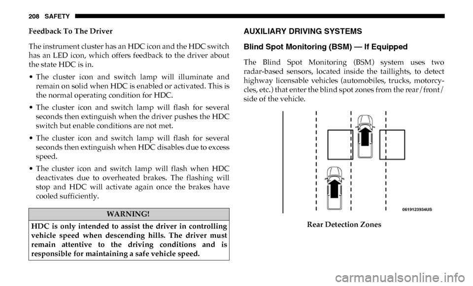
The Blind Spot Monitoring (BSM) system uses two
radar-based sensors, located inside the taillights, to detect
highway licensable vehicles (automobiles, trucks, motorcy -
cles, etc.) that enter the blind spot zones from the rear/front/
side of the vehicle.
Rear Detection Zones
WARNING!
HDC is only intended to assist the driver in controlling
vehicle speed when descending hills. The driver must
remain attentive to the driving conditions and is
responsible for maintaining a safe vehicle speed.
Page 216 of 696

214 SAFETY
(5 km/h), to objects moving a maximum of approximately
20 mph (32 km/h), such as in parking lot situations.
NOTE:
In a parking lot situation, oncoming vehicles can be obscured
by vehicles parked on either side. If the sensors are blocked
by other structures or vehicles, the system will not be able to
alert the driver.
When RCP is on and the vehicle is in REVERSE, the driver is
alerted using both the visual and audible alarms, including
reducing the radio volume.Modes Of Operation
Three selectable modes of operation are available in the
Uconnect System.
Refer to “Uconnect Settings” in “Multimedia” for further
information.
Blind Spot Alert Lights Only
When operating in Blind Spot Alert mode, the BSM system
will provide a visual alert in the appropriate side view
mirror based on a detected object. However, when the
system is operating in Rear Cross Path (RCP) mode, the
system will respond with both visual and audible alerts
when a detected object is present. Whenever an audible alert
is requested, the radio is muted.
Blind Spot Alert Lights/Chime
When operating in Blind Spot Alert Lights/Chime mode, the
BSM system will provide a visual alert in the appropriate
side view mirror based on a detected object. If the turn signal
is then activated, and it corresponds to an alert present on
that side of the vehicle, an audible chime will also be
sounded. Whenever a turn signal and detected object are
WARNING!
Rear Cross Path Detection (RCP) is not a back up aid
system. It is intended to be used to help a driver detect
an oncoming vehicle in a parking lot situation. Drivers
must be careful when backing up, even when using RCP.
Always check carefully behind your vehicle, look
behind you, and be sure to check for pedestrians,
animals, other vehicles, obstructions, and blind spots
before backing up. Failure to do so can result in serious
injury or death.
Page 217 of 696

SAFETY 215
present on the same side at the same time, both the visual
and audible alerts will be issued. In addition to the audible
alert the radio (if on) will also be muted.
NOTE:
Whenever an audible alert is requested by the BSM system,
the radio is also muted.
When the system is in RCP, the system shall respond with
both visual and audible alerts when a detected object is
present. Whenever an audible alert is requested, the radio is
also muted. Turn/hazard signal status is ignored; the RCP
state always requests the chime.
Blind Spot Alert Off
When the BSM system is turned off there will be no visual or
audible alerts from either the BSM or RCP systems.
NOTE:
The BSM system will store the current operating mode when
the vehicle is shut off. Each time the vehicle is started the
previously stored mode will be recalled and used.General Information
The following regulatory statement applies to all Radio
Frequency (RF) devices equipped in this vehicle:
This device complies with Part 15 of the FCC Rules and with
Industry Canada license-exempt RSS standard(s). Operation
is subject to the following two conditions:
1. This device may not cause harmful interference.
2. This device must accept any interference received,
including interference that may cause undesired opera -
tion.
NOTE:
Changes or modifications not expressly approved by the
party responsible for compliance could void the user’s
authority to operate the equipment.
4
Page 219 of 696

SAFETY 217
NOTE:
• The minimum speed for FCW activation is 3 mph (5 km/h).
• The FCW alerts may be triggered on objects other than vehicles such as guard rails or sign posts based on the
course prediction. This is expected and is a part of normal
FCW activation and functionality.
• It is unsafe to test the FCW system. To prevent such misuse of the system, after four Active Braking events within a
key cycle, the Active Braking portion of FCW will be deac -
tivated until the next key cycle.
• The FCW system is intended for on-road use only. If the vehicle is taken off-road, the FCW system should be deac -
tivated to prevent unnecessary warnings to the surround -
ings.
• FCW may not react to irrelevant objects such as overhead objects, ground reflections, objects not in the path of the
vehicle, stationary objects that are far away, oncoming
traffic, or leading vehicles with the same or higher rate of
speed.
• “FCW will be disabled like ACC, with the unavailable screens. Turning FCW On or Off
The FCW button is located in the Uconnect display in the
control settings. Refer to “Uconnect Settings” in “Multi
-
media” in the Owner's Manual for further information.
• To turn the FCW system on, press the forward collision button once to turn the system on.
• To turn the FCW system off, press the forward collision button once to turn the system off.
NOTE:
• When the FCW is “on”, this allows the system to warn the driver of a possible collision with the vehicle in front.
• When the FCW is “off” prevents the system from warning the driver of a possible collision with the vehicle in front.
If the FCW is set to “off”, “FCW OFF" will be displayed in
the instrument cluster display.WARNING!
Forward Collision Warning (FCW) is not intended to
avoid a collision on its own, nor can FCW detect every
type of potential collision. The driver has the
responsibility to avoid a collision by controlling the
vehicle via braking and steering. Failure to follow this
warning could lead to serious injury or death.
4
Page 221 of 696

SAFETY 219
FCW Limited Warning
If the instrument cluster displays “ACC/FCW Limited Func-
tionality” or “ACC/FCW Limited Functionality Clean Front
Windshield” momentarily, there may be a condition that
limits FCW functionality. Although the vehicle is still driv -
able under normal conditions, the active braking may not be
fully available. Once the condition that limited the system
performance is no longer present, the system will return to
its full performance state. If the problem persists, see an
authorized dealer.
Service FCW Warning
If the system turns off, and the instrument cluster displays:
• ACC/FCW Unavailable Service Required
• Cruise/FCW Unavailable Service Required
This indicates there is an internal system fault. Although the
vehicle is still drivable under normal conditions, have the
system checked by an authorized dealer. General Information
The following regulatory statement applies to all Radio
Frequency (RF) devices equipped in this vehicle:
This device complies with Part 15 of the FCC Rules and with
Industry Canada license-exempt RSS standard(s). Operation
is subject to the following two conditions:
1. This device may not cause harmful interference.
2. This device must accept any interference received,
including interference that may cause undesired opera -
tion.
NOTE:
Changes or modifications not expressly approved by the
party responsible for compliance could void the user’s
authority to operate the equipment.
4
Page 224 of 696

222 SAFETY
• The TPMS is not a substitute for proper tire maintenance,and it is the driver’s responsibility to maintain correct tire
pressure using an accurate tire pressure gauge, even if
under-inflation has not reached the level to trigger illumi -
nation of the TPMS Warning Light.
• Seasonal temperature changes will affect tire pressure, and the TPMS will monitor the actual tire pressure in the tire.
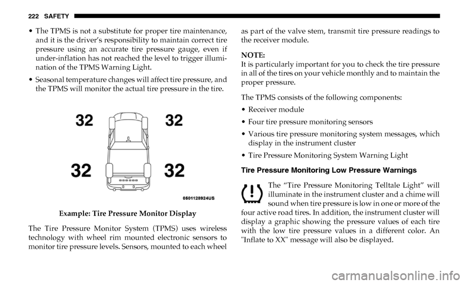
Example: Tire Pressure Monitor Display
The Tire Pressure Monitor System (TPMS) uses wireless
technology with wheel rim mounted electronic sensors to
monitor tire pressure levels. Sensors, mounted to each wheel as part of the valve stem, transmit tire pressure readings to
the receiver module.
NOTE:
It is particularly important for you to check the tire pressure
in all of the tires on your vehicle monthly and to maintain the
proper pressure.
The TPMS consists of the following components:
• Receiver module
• Four tire pressure monitoring sensors
• Various tire pressure monitoring system messages, which
display in the instrument cluster
• Tire Pressure Monitoring System Warning Light
Tire Pressure Monitoring Low Pressure Warnings
The “Tire Pressure Monitoring Telltale Light” will
illuminate in the instrument cluster and a chime will
sound when tire pressure is low in one or more of the
four active road tires. In addition, the instrument cluster will
display a graphic showing the pressure values of each tire
with the low tire pressure values in a different color. An
"Inflate to XX" message will also be displayed.
Page 232 of 696

230 SAFETY
General Information
This device complies with Part 15 of the FCC rules and RSS
210 of Industry Canada. Operation is subject to the following
conditions:
1. This device may not cause harmful interference.
2. This device must accept any interference received,including interference that may cause undesired opera -
tion.
NOTE:
Changes or modifications not expressly approved by the
party responsible for compliance could void the user’s
authority to operate the equipment.
OCCUPANT RESTRAINT SYSTEMS
Some of the most important safety features in your vehicle
are the restraint systems:
Occupant Restraint Systems Features
• Seat Belt Systems
• Supplemental Restraint Systems (SRS) Air Bags
• Child Restraints Some of the safety features described in this section may be
standard equipment on some models, or may be optional
equipment on others. If you are not sure, ask an authorized
dealer.
Important Safety Precautions
Please pay close attention to the information in this section.
It tells you how to use your restraint system properly, to
keep you and your passengers as safe as possible.
Here are some simple steps you can take to minimize the risk
of harm from a deploying air bag:
1. Children 12 years old and under should always ride
buckled up in the rear seat of a vehicle with a rear seat.
2. A child who is not big enough to wear the vehicle seat belt properly (Refer to “Child Restraints” in this section for
further information) must be secured in the appropriate
child restraint or belt-positioning booster seat in a rear
seating position.
3. If a child from 2 to 12 years old (not in a rear-facing child restraint) must ride in the front passenger seat, move the
seat as far back as possible and use the proper child
restraint (Refer to “Child Restraints” in this section for
further information).
Page 254 of 696

252 SAFETY
(Continued)
The SABICs may help reduce the risk of partial or complete
ejection of vehicle occupants through side windows in
certain side impact events.
Side Impacts
The Side Air Bags are designed to activate in certain side
impacts. The Occupant Restraint Controller (ORC) deter-
mines whether the deployment of the Side Air Bags in a
particular impact event is appropriate, based on the severity
and type of collision. The side impact sensors aid the ORC in
determining the appropriate response to impact events. The system is calibrated to deploy the Side Air Bags on the
impact side of the vehicle during impacts that require Side
Air Bag occupant protection. In side impacts, the Side Air
Bags deploy independently; a left side impact deploys the
left Side Air Bags only and a right-side impact deploys the
right Side Air Bags only. Vehicle damage by itself is not a
good indicator of whether or not Side Air Bags should have
deployed.
The Side Air Bags will not deploy in all side collisions,
including some collisions at certain angles, or some side
collisions that do not impact the area of the passenger
compartment. The Side Air Bags may deploy during angled
or offset frontal collisions where the front air bags deploy.
Side Air Bags are a supplement to the seat belt restraint
system. Side Air Bags deploy in less time than it takes to
blink your eyes.
WARNING!
• Do not mount equipment, or stack luggage or other cargo up high enough to block the deployment of the
SABICs. The trim covering above the side windows
where the SABIC and its deployment path are located
should remain free from any obstructions.
• In order for the SABICs to work as intended, do not install any accessory items in your vehicle which could
alter the roof. Do not add an aftermarket sunroof to
your vehicle. Do not add roof racks that require perma -
nent attachments (bolts or screws) for installation on
the vehicle roof. Do not drill into the roof of the vehicle
for any reason.
WARNING!
• Occupants, including children, who are up against or very close to Side Air Bags can be seriously injured or
killed. Occupants, including children, should never
lean on or sleep against the door, side windows, or area
where the side air bags inflate, even if they are in an
infant or child restraint.
Page 257 of 696

SAFETY 255
cool water. For nose or throat irritation, move to fresh air.
If the irritation continues, see your doctor. If these particles
settle on your clothing, follow the garment manufacturer’s
instructions for cleaning.
Do not drive your vehicle after the air bags have deployed. If
you are involved in another collision, the air bags will not be
in place to protect you.
NOTE:
• Air bag covers may not be obvious in the interior trim, but they will open during air bag deployment.
• After any collision, the vehicle should be taken to an authorized dealer immediately. Enhanced Accident Response System
In the event of an impact, if the communication network
remains intact, and the power remains intact, depending on
the nature of the event, the ORC will determine whether to
have the Enhanced Accident Response System perform the
following functions:
• Cut off fuel to the engine (If Equipped)
• Cut off battery power to the electric motor (If Equipped)
• Flash hazard lights as long as the battery has power
• Turn on the interior lights, which remain on as long as the
battery has power or for 15 minutes from the intervention
of the Enhanced Accident Response System.
• Unlock the power door locks.
Your vehicle may also be designed to perform any of these
other functions in response to the Enhanced Accident
Response System:
• Turn off the Fuel Filter Heater, Turn off the HVAC Blower Motor, Close the HVAC Circulation Door
WARNING!
Deployed air bags and seat belt pretensioners cannot
protect you in another collision. Have the air bags, seat
belt pretensioners, and the seat belt retractor assemblies
replaced by an authorized dealer immediately. Also,
have the Occupant Restraint Controller System serviced
as well.4
Page 258 of 696

256 SAFETY
(Continued)
• Cut off battery power to the:•Engine
•Electric Motor (if equipped)
•Electric power steering
•Brake booster
•Electric park brake
•Automatic transmission gear selector
•Horn
•Front wiper
•Headlamp washer pump
NOTE:
After an accident, remember to cycle the ignition to the STOP
(OFF/LOCK) position and remove the key from the ignition
switch to avoid draining the battery. Carefully check the
vehicle for fuel leaks in the engine compartment and on the
ground near the engine compartment and fuel tank before
resetting the system and starting the engine. If there are no
fuel leaks or damage to the vehicle electrical devices (e.g.
headlights) after an accident, reset the system by following
the procedure described below. If you have any doubt,
contact an authorized dealer. Enhanced Accident Response System Reset Procedure
In order to reset the Enhanced Accident Response System
functions after an event, the ignition switch must be changed
from ignition START or ON/RUN to ignition OFF. Carefully
check the vehicle for fuel leaks in the engine compartment
and on the ground near the engine compartment and fuel
tank before resetting the system and starting the engine.
Maintaining Your Air Bag System
WARNING!
• Modifications to any part of the air bag system could cause it to fail when you need it. You could be injured
if the air bag system is not there to protect you. Do not
modify the components or wiring, including adding
any kind of badges or stickers to the steering wheel hub
trim cover or the upper passenger side of the instru -
ment panel. Do not modify the front bumper, vehicle
body structure, or add aftermarket side steps or
running boards.
• It is dangerous to try to repair any part of the air bag system yourself. Be sure to tell anyone who works on
your vehicle that it has an air bag system.