reset Ram 3500 2020 User Guide
[x] Cancel search | Manufacturer: RAM, Model Year: 2020, Model line: 3500, Model: Ram 3500 2020Pages: 568
Page 125 of 568

GETTING TO KNOW YOUR INSTRUMENT PANEL123
Commercial SettingsCommercial
Aux Switches
Power Take-Off
PIN Setup
NOTE:
If the vehicle’s PIN is forgotten or not known, see
an authorized dealer to have the PIN reset.
Trailer Select Trailer SelectTrailer 1; Trailer 2; Trailer 3; Trailer 4
Brake Type Brake TypeLight Electric; Heavy Electric; Light EOH; Heavy
EOH
Setting Names
Setting Names Abbreviated
(Left Submenu Layer) Sub-Menus (Right Submenu Layer)
3
20_DJD2_OM_EN_USC_t.book Page 123
Page 127 of 568
GETTING TO KNOW YOUR INSTRUMENT PANEL125
Commercial Settings — If Equipped
Commercial Settings allows the driver to set
and recall additional features when the
transmission is in PARK (P).
Push and release the up and down button until
Commercial Settings displays in the instrument
cluster display.
Follow the prompts to enter the required PIN
and enter the Commercial Settings submenu.
Commercial Settings allows you to access the
following features (if equipped):
Backup Alarm — If Equipped
ParkSense — If Equipped
Aux Switches
PIN Setup
NOTE:
If the vehicle’s PIN is forgotten or not known,
see an authorized dealer to have the PIN reset.
DIESEL MESSAGES AND WARNINGS —
6.7L C
UMMINS DIESEL ENGINE
Diesel Particulate Filter (DPF) Messages
The Cummins diesel engine meets all diesel
emissions standards, resulting in one of the
lowest emitting diesel engines ever produced.
To achieve these emissions standards, your
vehicle is equipped with a state-of-the-art
engine and exhaust system. These systems are
seamlessly integrated into your vehicle and
managed by the Powertrain Control Module
(PCM). The PCM manages engine combustion
to allow the exhaust system’s catalyst to trap
and burn Particulate Matter (PM) pollutants,
with no input or interaction on your part. Your vehicle has the ability to alert you to
additional maintenance required on your
vehicle or engine. The following messages may
display in your instrument cluster display:Perform Service
— Your vehicle will require
emissions maintenance at a set interval. To
help remind you when this maintenance is
due, the instrument cluster display will
display “Perform Service”. When the
“Perform Service” message is displayed in
the instrument cluster display it is necessary
to have the emissions maintenance
performed. Emissions maintenance may
include replacing the Closed Crankcase
Ventilation (CCV) filter element. The proce -
dure for clearing and resetting the "Perform
Service" indicator message is located in the
appropriate Service Information.
Exhaust System — Regeneration Required
Now — "Exhaust Filter XX% Full Safely Drive at
Highway Speeds to Remedy" will be displayed
in the instrument cluster display if the
exhaust particulate filter reaches 80% of its
maximum storage capacity. Under conditions
of exclusive short duration and low speed
driving cycles, your Cummins diesel engine
and exhaust after-treatment system may
never reach the conditions required to
WARNING!
A hot exhaust system can start a fire if you
park over materials that can burn. Such
materials might be grass or leaves coming
into contact with your exhaust system. Do not
park or operate your vehicle in areas where
your exhaust system can contact anything
that can burn.
3
20_DJD2_OM_EN_USC_t.book Page 125
Page 128 of 568

126GETTING TO KNOW YOUR INSTRUMENT PANEL
remove the trapped Particulate Matter (PM).
If this occurs, the “Exhaust Filter XX% Full
Safely Drive at Highway Speeds to Remedy”
message will be displayed in the instrument
cluster display. If this message is displayed,
you will hear one chime to assist in alerting
you of this condition
By simply driving your vehicle at highway
speeds for as little as 45 minutes, you can
remedy the condition in the particulate filter
system and allow your Cummins diesel
engine and exhaust after-treatment system
to remove the trapped Particulate Matter
(PM) and restore the system to normal oper-
ating condition.
Exhaust System — Regeneration In Process
Exhaust Filter XX% Full — Indicates that the
Diesel Particulate Filter (DPF) is self-cleaning.
Maintain your current driving condition until
regeneration is completed.
Exhaust System — Regeneration Completed
— This message indicates that the Diesel
Particulate Filter (DPF) self-cleaning is
completed. If this message is displayed, you
will hear one chime to assist in alerting you of
this condition.
Exhaust Service Required — See Dealer Now
— This message indicates regeneration has
been disabled due to a system malfunction.
At this point the engine Powertrain Control
Module (PCM) will register a fault code, the
instrument panel will display a MIL light.
Exhaust Filter Full — Power Reduced See
Dealer — This message indicates the PCM
has derated the engine to limit the likelihood
of permanent damage to the after-treatment
system. If this condition is not corrected and
a dealer service is not performed, extensive
exhaust after-treatment damage can occur.
To correct this condition it will be necessary
to have your vehicle serviced by your local
authorized dealer.
NOTE:
Failing to follow the oil change indicator,
changing your oil and resetting the oil change
indicator by 0 miles remaining will prevent the
diesel exhaust filter from performing it's cleaning routine. This will shortly result in a
Malfunction Indicator Light (MIL) and reduced
engine power. Only an authorized dealer will be
able to correct this condition.
Cold Ambient Derate Mode Messages
The vehicle will display messages when a
derate (engine power reduction) is activated to
protect the engine during start up in cold
ambient temperatures.
Engine Power Reduced During Warmup
—
This message will display during start up
when the ambient temperature is between
10°F (-12°C) and -10°F (-23°C).
Engine Power Reduced Up To 30 Sec
(Seconds) During Warmup — This message
will display during start up when the ambient
temperature is between -10°F (-23°C) and
-25°F (-32°C).
CAUTION!
See an authorized dealer, as damage to the
exhaust system could occur soon with
continued operation.
CAUTION!
See an authorized dealer, as damage to the
exhaust system could occur soon with
continued operation.
20_DJD2_OM_EN_USC_t.book Page 126
Page 156 of 568
154SAFETY
operate when the vehicle is in any forward gear
or REVERSE and enters standby mode when the
vehicle is in PARK.
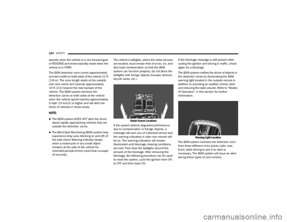
The BSM detection zone covers approximately
one lane width on both sides of the vehicle 12 ft
(3.8 m). The zone length starts at the outside
rear view mirror and extends approximately
10 ft (3 m) beyond the rear bumper of the
vehicle. The BSM system monitors the
detection zones on both sides of the vehicle
when the vehicle speed reaches approximately
6 mph (10 km/h) or higher and will alert the
driver of vehicles in these areas.
NOTE:
The BSM system DOES NOT alert the driver
about rapidly approaching vehicles that are
outside the detection zones.
The Blind Spot Monitoring (BSM) system may
experience drop outs (blinking on and off) of
the side mirror Warning Indicator lamps
when a motorcycle or any small object
remains at the side of the vehicle for
extended periods of time (more than a couple
of seconds). The vehicle’s taillights, where the radar sensors
are located, must remain free of snow, ice, and
dirt/road contamination so that the BSM
system can function properly. Do not block the
taillights with foreign objects (bumper stickers,
bicycle racks, etc.).
Radar Sensor Locations
If the system detects degraded performance
due to contamination or foreign objects, a
message will warn you of a blocked sensor and
the warning indicators in side view mirrors will
be on. The warning indicators will remain
illuminated until blockage clearing conditions
are met. First clear the taillights around the
sensors of the blockage. After removing the
blockage, the following procedure can be used
to reset the system, cycle the ignition from ON
to OFF and then back ON. If the blockage message is still present after
cycling the ignition and driving in traffic, check
again for a blockage.
The BSM system notifies the driver of objects in
the detection zones by illuminating the BSM
warning light located in the outside mirrors in
addition to sounding an audible (chime) alert
and reducing the radio volume. Refer to “Modes
Of Operation” in this section for further
information.
Warning Light Location
The BSM system monitors the detection zone
from three different entry points (side, rear,
front) while driving to see if an alert is
necessary. The BSM system will issue an alert
during these types of zone entries.
20_DJD2_OM_EN_USC_t.book Page 154
Page 160 of 568
158SAFETY
NOTE:
When a trailer with an electric brake is
connected to the vehicle, the instrument cluster
display will provide a menu to allow a selection
of the trailer type. There will be two options
provided: Conventional and Goose/Fifth Wheel.
Goose/Fifth Wheel Trailer is incompatible and
when selected, the BSM system will disable
until the trailer is disconnected. If the wrong
option is selected, the system can be reset by
either disconnecting and reconnecting the
trailer harness connector or disabling then
re-enabling the Blind Spot Monitoring System in
the customer settings in the Uconnect. This will
prompt the trailer selection menu again to allow
for the correct selection.
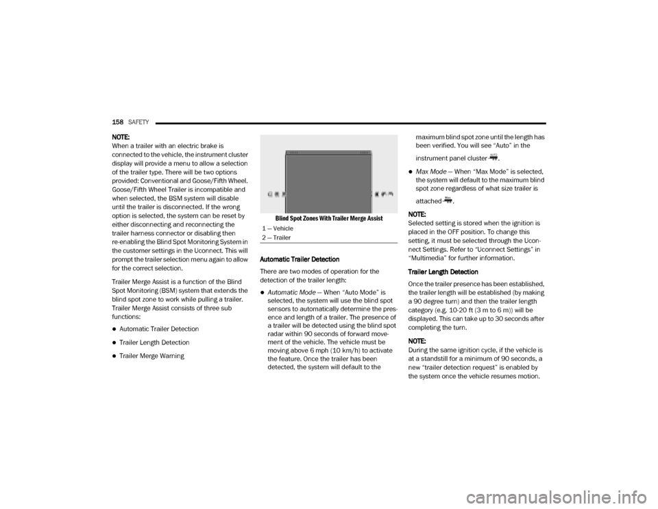
Trailer Merge Assist is a function of the Blind
Spot Monitoring (BSM) system that extends the
blind spot zone to work while pulling a trailer.
Trailer Merge Assist consists of three sub
functions:
Automatic Trailer Detection
Trailer Length Detection
Trailer Merge Warning
Blind Spot Zones With Trailer Merge Assist
Automatic Trailer Detection
There are two modes of operation for the
detection of the trailer length:
Automatic Mode — When “Auto Mode” is
selected, the system will use the blind spot
sensors to automatically determine the pres -
ence and length of a trailer. The presence of
a trailer will be detected using the blind spot
radar within 90 seconds of forward move -
ment of the vehicle. The vehicle must be
moving above 6 mph (10 km/h) to activate the feature. Once the trailer has been
detected, the system will default to the maximum blind spot zone until the length has
been verified. You will see “Auto” in the
instrument panel cluster .
Max Mode
— When “Max Mode” is selected,
the system will default to the maximum blind
spot zone regardless of what size trailer is
attached .
NOTE:
Selected setting is stored when the ignition is
placed in the OFF position. To change this
setting, it must be selected through the Ucon -
nect Settings. Refer to “Uconnect Settings” in
“Multimedia” for further information.
Trailer Length Detection
Once the trailer presence has been established,
the trailer length will be established (by making
a 90 degree turn) and then the trailer length
category (e.g. 10-20 ft (3 m to 6 m)) will be
displayed. This can take up to 30 seconds after
completing the turn.
NOTE:
During the same ignition cycle, if the vehicle is
at a standstill for a minimum of 90 seconds, a
new “trailer detection request” is enabled by
the system once the vehicle resumes motion.
1 — Vehicle
2 — Trailer
20_DJD2_OM_EN_USC_t.book Page 158
Page 164 of 568

162SAFETY
NOTE:
When the FCW is “on”, this allows the system
to warn the driver of a possible collision with
the vehicle in front.
When the FCW is “off” prevents the system
from warning the driver of a possible collision
with the vehicle in front. If the FCW is set to
“off”, “FCW OFF" will be displayed in the
instrument cluster display.
When FCW status is set to “Only Warning”
prevents the system from providing limited
active braking, or additional brake support if
the driver is not braking adequately in the
event of a potential frontal collision.
When FCW status is set to “Warning and
Braking” this allows the system to warn the
driver of a possible collision with the vehicle
in front using audible/visual warnings and it
applies autonomous braking.
The FCW system state is defaulted to “Full
On” from one ignition cycle to the next. If the
system is turned off, it will reset to “Full On”
when the vehicle is restarted.
FCW Braking Status And Sensitivity
The FCW sensitivity and Active Braking status
are programmable through the Uconnect
System. Refer to “Uconnect Settings” in
“Multimedia” for further information.
Far
When the sensitivity of FCW is set to the
“Far” setting and the system status is
“Warning and Braking”, this allows the
system to warn the driver of a possible
more distant collision with the vehicle in
front using audible/visual warnings.
More cautious drivers that do not mind
frequent warnings may prefer this
setting.
Medium
When the sensitivity of FCW is set to the
“Medium” setting and the system status
is “Warning and Braking”, this allows the
system to warn the driver of a possible
collision with the vehicle in front using
audible/visual warnings.
Near
When the sensitivity of FCW is set to the
“Near” setting and the system status is
“Warning and Braking”, this allows the
system to warn the driver of a possible
closer collision with the vehicle in front
using audible/visual warnings.
This setting provides less reaction time
than the “Far” and “Medium” settings,
which allows for a more dynamic driving
experience.
More dynamic or aggressive drivers that
want to avoid frequent warnings may
prefer this setting.
FCW Limited Warning
If the instrument cluster displays “ACC/FCW
Limited Functionality” or “ACC/FCW Limited
Functionality Clean Front Windshield”
momentarily, there may be a condition that
limits FCW functionality. Although the vehicle is
still drivable under normal conditions, the active
braking may not be fully available. Once the
condition that limited the system performance
is no longer present, the system will return to its
full performance state. If the problem persists,
see an authorized dealer.
20_DJD2_OM_EN_USC_t.book Page 162
Page 172 of 568
170SAFETY
If the hazard lamps do not come on while inflating
the tire, the TPM sensor may be in a inoperative
position, preventing the TPM sensor signal from
being received. In this case, the vehicle may need
to be moved slightly forward or backward.
When Tire Fill Alert Mode is entered, the tire
pressure display screen will be displayed in the
instrument cluster.
Operation:
The horn will chirp once to let the user know
when to stop filling the tire, when it reaches
recommended pressure.
The horn will chirp three times if the tire is
over filled and will continue to chirp every five
seconds if the user continues to inflate the
tire.
The horn will chirp once again when enough
air is let out to reach proper inflation level.
The horn will also chirp three times if the tire
is then under-inflated and will continue to
chirp every five seconds if the user continues
to deflate the tire. Selectable Tire Fill Alert (STFA)
The Selectable Tire Fill Alert (STFA) system is an
optional feature that is included as part of the
normal Tire Fill Alert system. The system is
designed to allow the customer to select a
pressure to inflate or deflate the vehicle's front
and rear axle tires to and to provide feedback to
the customer while inflating or deflating the
vehicle's tires.
In the Selectable Tire Fill Alert application,
which is located in the apps menu of the
Uconnect System, the customer will be able to
select a pressure setting for both the front and
rear axle tire pressures by scrolling through a
pressure range from XX to 15 psi in 1 psi
increments for each axle setting. XX = the
vehicle’s cold placard pressure values for the
front and rear axles as shown on the vehicle
placard pressure label.
The customer may also store the pressure
values chosen for each axle in the radio as a
preset pressure. The customer will be allowed
to store up to two sets of preset values in the
radio for the front and rear axle pressure values. Once the customer selects the tire pressures for
the front and rear axles that they want to inflate
or deflate to, they can begin inflating or
deflating one tire at a time.
NOTE:
The STFA system will only support inflating or
deflating one tire at a time.
The system will be activated when the TPM
receiver module detects a change in tire
pressure. The ignition must be in the RUN
mode, with the transmission in PARK (P).
The hazard lamps will come on to confirm the
vehicle is in Tire Fill Alert mode.
If the hazard lamps do not come on while
inflating or deflating the tire, the TPM sensor
may be in a inoperative position, preventing the
TPM sensor signal from being received. In this
case, the vehicle may need to be moved slightly
forward or backward.
When Tire Fill Alert Mode is entered, the tire
pressure display screen will be displayed in the
instrument cluster.
20_DJD2_OM_EN_USC_t.book Page 170
Page 191 of 568
SAFETY189
eye irritation, rinse the area with cool water.
For nose or throat irritation, move to fresh air.
If the irritation continues, see your doctor. If
these particles settle on your clothing, follow
the garment manufacturer’s instructions for
cleaning.
Do not drive your vehicle after the air bags have
deployed. If you are involved in another
collision, the air bags will not be in place to
protect you.
NOTE:
Air bag covers may not be obvious in the inte -
rior trim, but they will open during air bag
deployment.
After any collision, the vehicle should be
taken to an authorized dealer immediately.
Enhanced Accident Response System
In the event of an impact, if the communication
network remains intact, and the power remains
intact, depending on the nature of the event,
the Occupant Restraint Controller (ORC) will
determine whether to have the Enhanced
Accident Response System perform the
following functions:
Cut off fuel to the engine (if equipped)
Cut off battery power to the electric motor (if
equipped)
Flash hazard lights as long as the battery has
power
Turn on the interior lights, which remain on
as long as the battery has power or for
15 minutes from the intervention of the
Enhanced Accident Response System
Unlock the power door locks
Your vehicle may also be designed to perform
any of these other functions in response to the
Enhanced Accident Response System:
Turn off the Fuel Filter Heater, Turn off the
HVAC Blower Motor, Close the HVAC Circula -
tion Door
Cut off battery power to the:
Engine
Electric Motor (if equipped)
Electric power steering
Brake booster
Electric park brake
Automatic transmission gear selector
Horn
Front wiper
Headlamp washer pump
NOTE:
After an accident, remember to cycle the igni -
tion to the STOP (OFF/LOCK) position and
remove the key from the ignition switch to avoid
draining the battery. Carefully check the vehicle
for fuel leaks in the engine compartment and on
the ground near the engine compartment and
fuel tank before resetting the system and
starting the engine. If there are no fuel leaks or
damage to the vehicle electrical devices (e.g.
headlights) after an accident, reset the system
by following the procedure described below. If
you have any doubt, contact an authorized
dealer.
WARNING!
Deployed air bags and seat belt
pretensioners cannot protect you in another
collision. Have the air bags, seat belt
pretensioners, and the seat belt retractor
assemblies replaced by an authorized dealer
immediately. Also, have the Occupant
Restraint Controller System serviced as well.
4
20_DJD2_OM_EN_USC_t.book Page 189
Page 192 of 568
190SAFETY
(Continued)
Enhanced Accident Response System
Reset Procedure
In order to reset the Enhanced Accident
Response System functions after an event, the
ignition switch must be changed from ignition
START or ON/RUN to ignition OFF. Carefully
check the vehicle for fuel leaks in the engine
compartment and on the ground near the
engine compartment and fuel tank before
resetting the system and starting the engine.
Maintaining Your Air Bag System Event Data Recorder (EDR)
This vehicle is equipped with an event data
recorder (EDR). The main purpose of an EDR is
to record, in certain crash or near crash-like
situations, such as an air bag deployment or
hitting a road obstacle, data that will assist in
understanding how a vehicle’s systems
performed. The EDR is designed to record data
related to vehicle dynamics and safety systems
for a short period of time, typically 30 seconds
or less. The EDR in this vehicle is designed to
record such data as:
How various systems in your vehicle were
operating;
Whether or not the driver and passenger
safety belts were buckled/fastened;
How far (if at all) the driver was depressing
the accelerator and/or brake pedal; and,
How fast the vehicle was traveling.
These data can help provide a better
understanding of the circumstances in which
crashes and injuries occur.
WARNING!
Modifications to any part of the air bag
system could cause it to fail when you need
it. You could be injured if the air bag system
is not there to protect you. Do not modify
the components or wiring, including adding
any kind of badges or stickers to the
steering wheel hub trim cover or the upper
passenger side of the instrument panel. Do
not modify the front bumper, vehicle body
structure, or add aftermarket side steps or
running boards.
It is dangerous to try to repair any part of
the air bag system yourself. Be sure to tell
anyone who works on your vehicle that it
has an air bag system.
Do not attempt to modify any part of your
air bag system. The air bag may inflate acci -
dentally or may not function properly if
modifications are made. Take your vehicle
to an authorized dealer for any air bag
system service. If your seat, including your
trim cover and cushion, needs to be
serviced in any way (including removal or
loosening/tightening of seat attachment
bolts), take the vehicle to an authorized
dealer. Only manufacturer approved seat
accessories may be used. If it is necessary
to modify the air bag system for persons
with disabilities, contact an authorized
dealer.
WARNING! (Continued)
20_DJD2_OM_EN_USC_t.book Page 190
Page 222 of 568
220STARTING AND OPERATING
5. After engine start-up, check to see that
there is oil pressure.
6. Release the parking brake and drive.
NOTE:
Engine idle speed will automatically increase
to 1,000 RPM and engage the Variable
Geometry Turbocharger at low coolant
temperatures to improve engine warm-up.
The engine will not automatically crank after
the engine “Wait To Start” telltale goes off if
a door or the hood is ajar.
If the engine stalls, or if the ignition switch is
left ON for more than two minutes after the
“Wait To Start” telltale goes out, reset the
intake air heater by turning the ignition switch
to the OFF position for at least 5 seconds and
then back ON. Repeat steps 1 through 7 of
“Keyless Enter-N-Go Starting Procedure –
Engine Manifold Air Temperature Below 66° F
(19° C).”
EXTREME COLD WEATHER
The Cummins® Turbo Diesel engine is
equipped with several features designed to
assist cold weather starting and operation:
The engine block heater is a resistance
heater installed in the water jacket of the
engine just above and behind the oil filter. It
requires a 110–115 Volt AC electrical outlet
with a grounded, three-wire extension cord.
NOTE:
The engine block heater cord is a factory
installed option. If your vehicle is not equipped,
heater cords are available from an authorized
Mopar dealer.
A 12 Volt heater built into the fuel filter hous -
ings aid in preventing fuel gelling. It is
controlled by a built-in thermostat.
A intake air heater system both improves
engine starting and reduces the amount of
white smoke generated by a warming engine.
NORMAL STARTING PROCEDURE —
E
NGINE MANIFOLD AIR TEMPERATURE
A
BOVE 66° F (19° C)
Observe the instrument panel cluster lights
when starting the engine.
1. Always apply the parking brake.
2. Shift into PARK for an automatic
transmission.
3. Place the ignition switch in the ON position and watch the instrument panel cluster
lights.
4. Place the ignition switch in the START position and crank the engine. Do not press
the accelerator during starting.
CAUTION!
If the “Water in Fuel Indicator Light” remains
on, DO NOT START the engine before you
drain the water from the fuel filters to avoid
engine damage. Refer to “Draining Fuel/
Water Separator Filter” in “Servicing And
Maintenance” for further information.
20_DJD2_OM_EN_USC_t.book Page 220