battery replacement Ram 3500 2020 Owner's Manual
[x] Cancel search | Manufacturer: RAM, Model Year: 2020, Model line: 3500, Model: Ram 3500 2020Pages: 568
Page 10 of 568
8
BULB REPLACEMENT ....................................... 351 Replacement Bulbs ..................................351Replacing Exterior Bulbs ...........................353
FUSES .................................................................. 358
Power Distribution Center .........................358
JACKING AND TIRE CHANGING ...................... 365
Jack Location .............................................365Removal Of Jack And Tools .......................365
Removing The Spare Tire ..........................367
Preparations For Jacking...........................368
Jacking Instructions ...................................368
To Stow The Flat Or Spare ........................ 372Reinstalling The Jack And Tools ...............373
Hub Caps/Wheel Covers — If Equipped ...374
JUMP STARTING ................................................ 375
Preparations For Jump Start .....................375Jump Starting Procedure...........................376
GEAR SELECTOR OVERRIDE — 6–SPEED
TRANSMISSION ................................................ 377
MANUAL PARK RELEASE — 8 – SPEED
TRANSMISSION ................................................ 378
IF YOUR ENGINE OVERHEATS ......................... 379
FREEING A STUCK VEHICLE ............................ 380 TOWING A DISABLED VEHICLE .......................381
Two-Wheel Drive Models ........................... 382
Four-Wheel Drive Models .......................... 383Emergency Tow Hooks — If Equipped ...... 384
ENHANCED ACCIDENT RESPONSE
SYSTEM (EARS) ................................................. 384
EVENT DATA RECORDER (EDR) .......................384
SERVICING AND MAINTENANCE
SCHEDULED SERVICING — GAS ENGINE .......385
Maintenance Plan — Gasoline Engine...... 386
Heavy Duty Use Of The Vehicle................. 389
SCHEDULED SERVICING— DIESEL ENGINE .... 389
Oil Change Indicator System —
Cummins Diesel......................................... 390 Perform Service Indicator —
Cummins Diesel ........................................ 390 Maintenance Plan — Cummins Diesel
Engine ........................................................ 391
ENGINE COMPARTMENT .................................. 396
6.4L Engine ................................................ 396
6.7L Diesel Engine — Six-Speed 68RFE ... 397
6.7L Diesel Engine — Six-Speed AISIN
(AS69RC HD) .............................................. 398 Checking Oil Level — Gas Engine ............. 399
Checking Oil Level — Diesel Engine .......... 399
Adding Washer Fluid ................................. 399Maintenance-Free Battery ....................... 400Pressure Washing...................................... 400
DEALER SERVICE .............................................. 401
Engine Oil .................................................. 401
Engine Oil Filter ......................................... 403Engine Air Cleaner Filter ........................... 403
Air Conditioner Maintenance ................... 405
Accessory Drive Belt Inspection ............... 408Draining Fuel/Water Separator Filter —
Diesel Engine ............................................ 409 Engine Mounted Fuel Filter
Replacement — Diesel Engine .................. 410 Underbody Mounted Fuel Filter
Replacement — Diesel Engine .................. 412 Priming If The Engine Has Run Out Of
Fuel — Diesel Engine ................................. 412 Intervention Regeneration Strategy —
Message Process Flow ............................. 413 Diesel Exhaust Fluid .................................. 414
Body Lubrication ........................................ 414
20_DJD2_OM_EN_USC_t.book Page 8
Page 17 of 568
GETTING TO KNOW YOUR VEHICLE15
The turn signal lights will flash to acknowledge the
unlock signal. The illuminated entry system will
also turn on.
NOTE:
All doors can be programmed to unlock on the
first push of the unlock button. Refer to “Ucon -
nect Settings” in “Multimedia” for further infor -
mation.
To Lock The Doors And Tailgate
Push and release the lock button on the key fob
to lock all doors, the tailgate, and the RamBox
(if equipped). The turn signal lights will flash and
the horn will chirp to acknowledge the signal.
Sound Horn With Remote Key Lock — If
Equipped
This feature will cause the horn to chirp when
the doors are locked with the key fob. This
feature can be turned on or turned off through
the Uconnect Settings. NOTE:
Pushing the lock button on the key fob while you
are in the vehicle will activate the vehicle secu
-
rity alarm system. Opening a door with the
vehicle security alarm system activated will
cause the alarm to sound. Push the unlock
button to deactivate the vehicle security alarm
system.
Refer to “Vehicle Security Alarm” in this chapter
for further information.
Using The Panic Alarm
To turn the Panic Alarm feature on or off, push
the Panic button on the key fob. When the Panic
Alarm is activated, the turn signals will flash, the
horn will pulse on and off, and the interior lights
will turn on.
The Panic Alarm will stay on for three minutes
unless you turn it off by either pushing the Panic
button a second time or drive the vehicle at a
speed of 15 mph (24 km/h) or greater. NOTE:
The interior lights will turn off if you place the
ignition in the ACC or ON/RUN position while
the Panic Alarm is activated. However, the
exterior lights and horn will remain on.
You may need to be less than 35 ft (11 m)
from the vehicle when using the key fob to
turn off the Panic Alarm due to the radio
frequency noises emitted by the system.
Replacing The Battery In The Key Fob With
Remote Control
The replacement battery model is one CR2450
battery.
NOTE:
Perchlorate Material — special handling may
apply. See www.dtsc.ca.gov/hazard
-
ouswaste/perchlorate for further informa -
tion.
Do not touch the battery terminals that are
on the back housing or the printed circuit
board.
2
20_DJD2_OM_EN_USC_t.book Page 15
Page 18 of 568
16GETTING TO KNOW YOUR VEHICLE
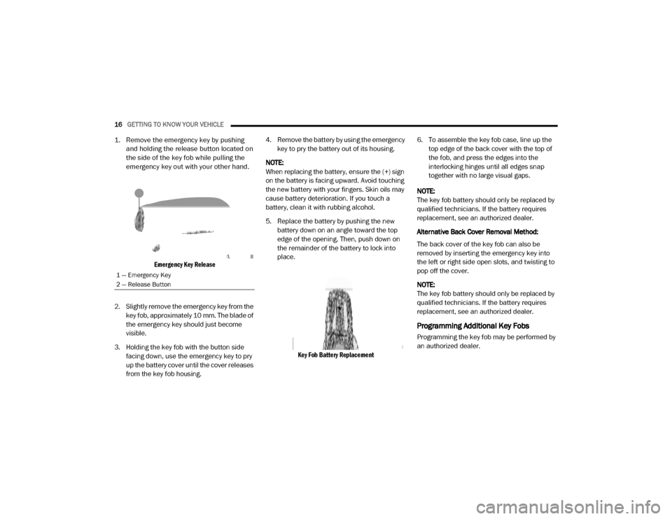
1. Remove the emergency key by pushing
and holding the release button located on
the side of the key fob while pulling the
emergency key out with your other hand.
Emergency Key Release
2. Slightly remove the emergency key from the key fob, approximately 10 mm. The blade of
the emergency key should just become
visible.
3. Holding the key fob with the button side facing down, use the emergency key to pry
up the battery cover until the cover releases
from the key fob housing. 4. Remove the battery by using the emergency
key to pry the battery out of its housing.
NOTE:
When replacing the battery, ensure the (+) sign
on the battery is facing upward. Avoid touching
the new battery with your fingers. Skin oils may
cause battery deterioration. If you touch a
battery, clean it with rubbing alcohol.
5. Replace the battery by pushing the new battery down on an angle toward the top
edge of the opening. Then, push down on
the remainder of the battery to lock into
place.
Key Fob Battery Replacement
6. To assemble the key fob case, line up the
top edge of the back cover with the top of
the fob, and press the edges into the
interlocking hinges until all edges snap
together with no large visual gaps.
NOTE:
The key fob battery should only be replaced by
qualified technicians. If the battery requires
replacement, see an authorized dealer.
Alternative Back Cover Removal Method:
The back cover of the key fob can also be
removed by inserting the emergency key into
the left or right side open slots, and twisting to
pop off the cover.
NOTE:
The key fob battery should only be replaced by
qualified technicians. If the battery requires
replacement, see an authorized dealer.
Programming Additional Key Fobs
Programming the key fob may be performed by
an authorized dealer.
1 — Emergency Key
2 — Release Button
20_DJD2_OM_EN_USC_t.book Page 16
Page 145 of 568
GETTING TO KNOW YOUR INSTRUMENT PANEL143
EMISSIONS INSPECTION AND
MAINTENANCE PROGRAMS
In some localities, it may be a legal requirement
to pass an inspection of your vehicle's
emissions control system. Failure to pass could
prevent vehicle registration.
For states that require an Inspection
and Maintenance (I/M), this check
verifies the “Malfunction Indicator
Light (MIL)” is functioning and is not
on when the engine is running, and that the
OBD II system is ready for testing.
Normally, the OBD II system will be ready. The
OBD II system may not be ready if your vehicle
was recently serviced, recently had a depleted
battery or a battery replacement. If the OBD II
system should be determined not ready for the
I/M test, your vehicle may fail the test.
Your vehicle has a simple ignition actuated test,
which you can use prior to going to the test
station. To check if your vehicle's OBD II system
is ready, you must do the following:
1. Cycle the ignition switch to the ON position,
but do not crank or start the engine.
NOTE:
If you crank or start the engine, you will have to
start this test over.
2. As soon as you cycle the ignition switch to the ON position, you will see the
“Malfunction Indicator Light (MIL)” symbol
come on as part of a normal bulb check.
3. Approximately 15 seconds later, one of two things will happen:
The MIL will flash for about 10 seconds and then return to being fully illuminated
until you turn OFF the ignition or start the
engine. This means that your vehicle's
OBD II system is not ready and you
should not proceed to the I/M station.
The MIL will not flash at all and will remain
fully illuminated until you place the ignition in
the off position or start the engine. This
means that your vehicle's OBD II system is
ready and you can proceed to the I/M station. If your OBD II system is not ready,
you should
see an authorized dealer or repair facility. If your
vehicle was recently serviced or had a battery
failure or replacement, you may need to do
nothing more than drive your vehicle as you
normally would in order for your OBD II system
to update. A recheck with the above test routine
may then indicate that the system is now ready.
Regardless of whether your vehicle's OBD II
system is ready or not, if the MIL is illuminated
during normal vehicle operation you should
have your vehicle serviced before going to the
I/M station. The I/M station can fail your vehicle
because the MIL is on with the engine running.
3
20_DJD2_OM_EN_USC_t.book Page 143
Page 355 of 568
IN CASE OF EMERGENCY353
REPLACING EXTERIOR BULBS
Base Quad: Low Beam Headlamp, High
Beam Headlamp, Front Park And Turn — If
Equipped
Low Beam
1. Open the hood.
2. Disconnect and isolate the negative battery
cable.
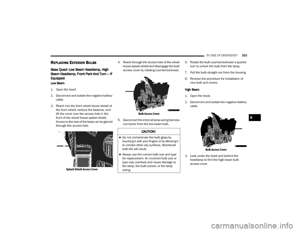
3. Reach into the front wheel house ahead of the front wheel, remove the fastener, and
lift the cover over the access hole in the
front of the wheel house splash shield.
Access to the rear of the lamp can be gained
through this access hole.
Splash Shield Access Cover
4. Reach through the access hole of the wheel
house splash shield and disengage the bulb
access cover by rotating counterclockwise.
Bulb Access Cover
5. Disconnect the internal lamp wiring harness connector from the low beam bulb. 6. Rotate the bulb counterclockwise a quarter
turn to unlock the bulb from the lamp.
7. Pull the bulb straight out from the housing.
8. Reverse the procedure for installation of new bulb and covers.
High Beam
1. Open the hood.
2. Disconnect and isolate the negative battery cable.
Bulb Access Cover
3. Look under the hood and behind the headlamp to find the high beam bulb
access cover.
CAUTION!
Do not contaminate the bulb glass by
touching it with your fingers or by allowing it
to contact other oily surfaces. Shortened
bulb life will result.
Always use the correct bulb size and type
for replacement. An incorrect bulb size or
type may overheat and cause damage to
the lamp, the bulb socket, or the lamp
wiring.
6
20_DJD2_OM_EN_USC_t.book Page 353
Page 356 of 568
354IN CASE OF EMERGENCY
4. Reach behind the headlamp and disengage
the access cover by rotating counter -
clockwise.
5. Disconnect the internal lamp wiring harness connector from the high beam bulb.
6. Rotate the bulb counterclockwise a quarter turn to unlock the bulb from the lamp.
7. Pull the bulb straight out from the housing.
8. Reverse the procedure for installation of new bulb and covers. Front Park And Turn
1. Open the hood.
2. Disconnect and isolate the negative battery
cable.
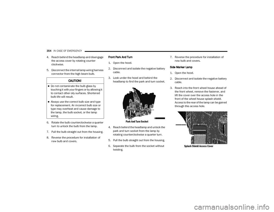
3. Look under the hood and behind the headlamp to find the park and turn socket.
Park And Turn Socket
4. Reach behind the headlamp and unlock the park and turn socket from the lamp by
rotating counterclockwise a quarter turn.
5. Pull the bulb straight out from the housing.
6. Separate the bulb from the socket without twisting. 7. Reverse the procedure for installation of
new bulb and covers.
Side Marker Lamp
1. Open the hood.
2. Disconnect and isolate the negative battery cable.
3. Reach into the front wheel house ahead of the front wheel, remove the fastener, and
lift the cover over the access hole in the
front of the wheel house splash shield.
Access to the rear of the lamp can be gained
through this access hole.
Splash Shield Access Cover
CAUTION!
Do not contaminate the bulb glass by
touching it with your fingers or by allowing it
to contact other oily surfaces. Shortened
bulb life will result.
Always use the correct bulb size and type
for replacement. An incorrect bulb size or
type may overheat and cause damage to
the lamp, the bulb socket, or the lamp
wiring.
20_DJD2_OM_EN_USC_t.book Page 354
Page 360 of 568
358IN CASE OF EMERGENCY
(Continued)
FUSES
POWER DISTRIBUTION CENTER
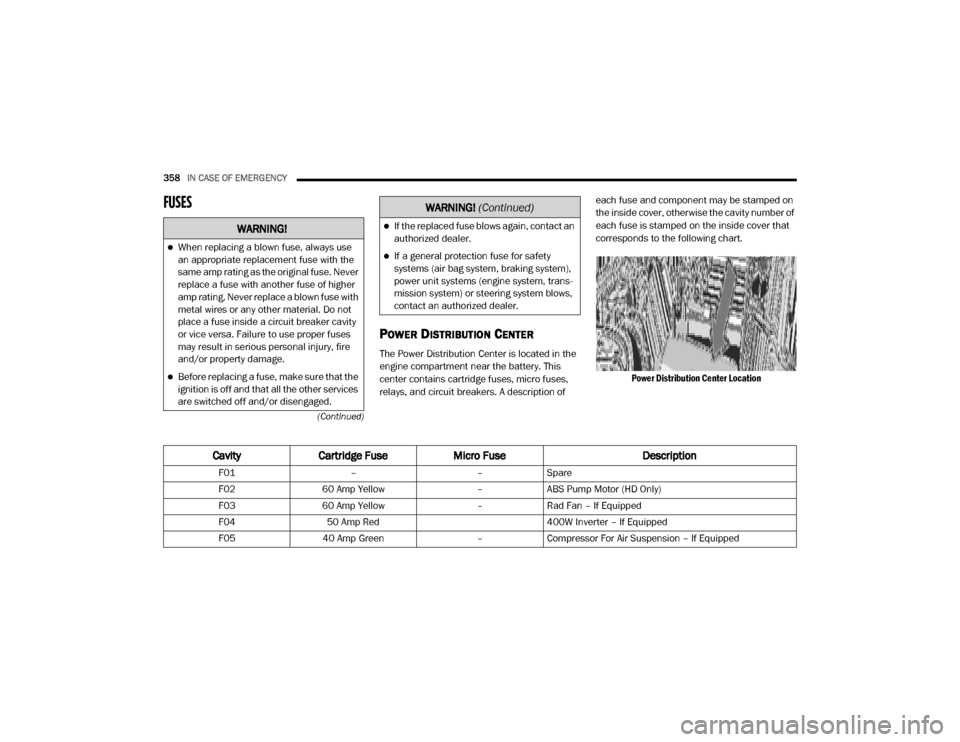
The Power Distribution Center is located in the
engine compartment near the battery. This
center contains cartridge fuses, micro fuses,
relays, and circuit breakers. A description of each fuse and component may be stamped on
the inside cover, otherwise the cavity number of
each fuse is stamped on the inside cover that
corresponds to the following chart.
Power Distribution Center Location
WARNING!
When replacing a blown fuse, always use
an appropriate replacement fuse with the
same amp rating as the original fuse. Never
replace a fuse with another fuse of higher
amp rating. Never replace a blown fuse with
metal wires or any other material. Do not
place a fuse inside a circuit breaker cavity
or vice versa. Failure to use proper fuses
may result in serious personal injury, fire
and/or property damage.
Before replacing a fuse, make sure that the
ignition is off and that all the other services
are switched off and/or disengaged.
If the replaced fuse blows again, contact an
authorized dealer.
If a general protection fuse for safety
systems (air bag system, braking system),
power unit systems (engine system, trans -
mission system) or steering system blows,
contact an authorized dealer.
WARNING! (Continued)
Cavity Cartridge Fuse Micro Fuse Description
F01––Spare
F02 60 Amp Yellow –ABS Pump Motor (HD Only)
F03 60 Amp Yellow –Rad Fan – If Equipped
F04 50 Amp Red 400W Inverter – If Equipped
F05 40 Amp Green –Compressor For Air Suspension – If Equipped
20_DJD2_OM_EN_USC_t.book Page 358
Page 388 of 568

386SERVICING AND MAINTENANCE
MAINTENANCE PLAN — GASOLINE ENGINE
Required Maintenance
Refer to the Maintenance Plan on the following pages for required maintenance. More frequent maintenance may be needed in severe conditions, such
as dusty areas and very short trip driving. In some extreme conditions, additional maintenance not specified in the maintenance schedule may be
required.
NOTE:
Using white lithium grease, lubricate the door hinge roller pivot joints twice a year to prevent premature wear.
At Every Oil Change Interval As Indicated By Oil Change Indicator System:
Change oil and filter.
Rotate the tires. Rotate at the first sign of irregular wear, even if it occurs before the oil indicator system turns on.
Inspect battery and clean and tighten terminals as required.
Inspect the CV/Universal joints.
Inspect brake pads, shoes, rotors, drums, hoses and park brake.
Inspect engine cooling system protection and hoses.
Inspect exhaust system.
Inspect engine air cleaner if using in dusty or off-road conditions. If required, replace air cleaner filter.
Inspect and replace the Evaporative System Fresh Air Filter as necessary, replacement may be more frequent if vehicle is operated in extreme
dusty conditions.
20_DJD2_OM_EN_USC_t.book Page 386
Page 554 of 568
552
INDEX
A
Adaptive Cruise Control (ACC)
(Cruise Control)
.............................................. 282Adding Engine Coolant (Antifreeze)............... 418Adding Fuel.......................................... 319, 320Additives, Fuel............................................... 454AdjustDown........................................................... 35Forward....................................................... 35Rearward..................................................... 35Up................................................................ 35Adjustable Pedals............................................ 42Air BagAir Bag Operation...................................... 185Air Bag Warning Light................................ 182Enhanced Accident Response......... 189, 384Event Data Recorder (EDR)....................... 384If Deployment Occurs................................ 188Knee Impact Bolsters................................ 185Maintaining Your Air Bag System.............. 190Maintenance............................................. 190Redundant Air Bag Warning Light.............183Transporting Pets...................................... 209Air Bag Light............................... 130, 182, 210Air Cleaner, Engine (Engine Air
Cleaner Filter)...................................... 403, 425
Air Conditioner Maintenance........................ 405Air Conditioner Refrigerant.................. 405, 406Air Conditioner System................................. 405Air Conditioning......................................... 57, 67Air Conditioning Filter..............................69, 406Air Conditioning System................................... 67Air Conditioning, Operating Tips....................... 68Air Filter........................................................ 403Air PressureTires......................................................... 436AlarmPanic........................................................... 15Security Alarm....................................25, 132Alterations/ModificationsVehicle......................................................... 12Android Auto................................................. 545Antifreeze (Engine Coolant)................. 418, 459Capacites................................................. 460Disposal................................................... 420Anti-Lock Brake System (ABS)...................... 144Anti-Lock Warning Light................................ 137Apple CarPlay................................................ 546Assist, Hill Start............................................. 151Audio Systems (Radio).................................. 467Auto Down Power Windows............................. 70Automatic Door Locks...................................... 30
Automatic Headlights.......................................50Automatic Tailgate Release.............................74Automatic Temperature Control (ATC)..............67Automatic Transmission....................... 235, 424Adding Fluid.............................................. 424Fluid And Filter Change............................. 424Fluid Change............................................. 424Fluid Level Check............................. 422, 423Fluid Type............................... 422, 463, 466Shifting..................................................... 239Special Additives...................................... 422Automatic Transmission Limp Home Mode... 238AUX Camera......................................... 311, 318Auxiliary Driving Systems.............................. 153Axle Fluid.....................................424, 463, 466Axle Lubrication............................................ 424
B
Back-Up......................................................... 309Back-Up Camera........................................... 309Bar, Stabilizer/Sway System......................... 260Battery................................................. 132, 400Blanket..................................................... 225Charging System Light.............................. 132Keyless Key Fob Replacement....................15Battery Saver Feature......................................53
20_DJD2_OM_EN_USC_t.book Page 552
Page 558 of 568

556 J
Jack Location
................................................. 365Jump Starting................................................ 375
K
Key Fob Panic Alarm
................................................. 15Programming Additional Key Fobs....... 16, 24Key Fob Battery Service (Remote
Keyless Entry).................................................. 15
Key Fob Programming (Remote Keyless Entry).. 16
Keyless Enter-N-Go........................28, 214, 218Lock The Vehicle’s Doors....... 476, 494, 514Passive Entry............................................... 28Passive Entry Programming............. 494, 514Keys................................................................. 14Replacement............................................... 24
L
Lane Change And Turn Signals........................ 51Lane Change Assist......................................... 52LaneSense.................................................... 306Latches.......................................................... 212Hood........................................................... 74Lead Free Gasoline........................................ 454Leaks, Fluid................................................... 212Life Of Tires................................................... 439Light Bulbs........................................... 212, 351
Lights............................................................ 212Air Bag.................................... 130, 182, 210Automatic High Beam.................................. 49Brake Assist Warning............................... 148Brake Warning.......................................... 131Bulb Replacement.................................... 351Cab Top Clearance................................... 357Cargo........................................................... 52Center Mounted Stop............................... 356Courtesy/Reading....................................... 53Cruise....................................................... 141Daytime Running......................................... 49
Electronic Stability Program(ESP) Indicator... 132
Exterior...............................................48, 212Fog........................................................... 355Four Wheel Drive Indicator....................... 255Hazard Warning Flasher........................... 346Headlights............................................ 48, 50High Beam................................................... 49Hill Descent Control Indicator................... 149Illuminated Entry......................................... 54Interior......................................................... 53Lights On Reminder..................................... 51Low Fuel................................................... 135Malfunction Indicator (Check Engine)....... 133Park.......................................................... 140Passing........................................................ 50Seat Belt Reminder.................................. 130Security Alarm.......................................... 132Service..................................................... 351
Side Marker.............................................. 357Traction Control........................................ 148Transfer Case........................................... 255Turn Signals............51, 141, 212, 353, 355Warning Instrument Cluster Descriptions................................ 132, 141Limited-Slip Differential....................... 270, 424Load Shed Battery Saver Mode..................... 129Load Shed Battery Saver On......................... 129Load Shed Electrical Load Reduction........... 129Load Shed Intelligent Battery Sensor............ 129Loading Vehicle............................................. 324Tires.......................................................... 433LocksAutomatic Door............................................30Child Protection...........................................30Power Door..................................................27Low Tire Pressure System............................. 163Lubrication, Body.......................................... 414Lug Nuts/Bolts.............................................. 452
M
Maintenance....................................................73Maintenance Free Battery............................ 400Maintenance Plan......................................... 391Maintenance Schedule............... 385, 389, 391Malfunction Indicator Light
(Check Engine)..................................... 133, 143
20_DJD2_OM_EN_USC_t.book Page 556