start stop button Ram 3500 2020 Owner's Manual
[x] Cancel search | Manufacturer: RAM, Model Year: 2020, Model line: 3500, Model: Ram 3500 2020Pages: 568
Page 7 of 568

5
SAFETY
SAFETY FEATURES ............................................ 144Anti-Lock Brake System (ABS) ................. 144
Electronic Brake Control (EBC) System ....145
AUXILIARY DRIVING SYSTEMS ........................ 153
Blind Spot Monitoring (BSM) —
If Equipped ................................................153 Forward Collision Warning (FCW) With
Mitigation — If Equipped............................160
Tire Pressure Monitoring System (TPMS) .. 163
OCCUPANT RESTRAINT SYSTEMS .................. 172
Occupant Restraint Systems Features ....172
Important Safety Precautions ...................172Seat Belt Systems ..................................... 173Supplemental Restraint Systems (SRS) ...182Child Restraints .........................................191
Transporting Pets ......................................209
SAFETY TIPS ...................................................... 209
Transporting Passengers ..........................209
Exhaust Gas ...............................................209Safety Checks You Should Make
Inside The Vehicle ..................................... 210 Periodic Safety Checks You Should
Make Outside The Vehicle ........................ 212
STARTING AND OPERATING
STARTING THE ENGINE — GAS ENGINE .........213
Automatic Transmission............................ 213
Tip Start Feature ....................................... 213Keyless Enter-N-Go — Ignition ................... 214
Normal Starting Using ENGINE
START/STOP Button ................................. 214 Cold Weather Operation (Below –22°F
Or −30°C) .................................................. 217 After Starting .............................................. 217
STARTING THE ENGINE — DIESEL ENGINE ..... 217
Automatic Transmission............................ 217
Keyless Enter-N-Go — Ignition ................... 218
Extreme Cold Weather .............................. 220
Normal Starting Procedure —
Engine Manifold Air Temperature
Above 66° F (19° C) ................................. 220 Starting Procedure —
Engine Manifold Air Temperature 0°F To
66°F (–18°C to 19°C) ............................. 221 Starting Procedure — Engine Manifold Air
Temperature Below 0°F (-18°C) .............. 222 Starting Fluids ............................................ 223 NORMAL OPERATION — DIESEL ENGINE ....... 223
Cold Weather Precautions ........................ 223
Engine Idling ............................................. 226
Noise .......................................................... 227
Stopping The Engine ................................. 227Idle Shutdown ............................................ 228
Programmable Maximum Vehicle Speed ... 228
Operating Precautions .............................. 228
Cooling System Tips .................................. 228
ENGINE BLOCK HEATER — GAS ENGINE
(IF EQUIPPED) .................................................... 229
ENGINE BLOCK HEATER — DIESEL ENGINE
(IF EQUIPPED) ................................................... 229
Block Heater Usage ................................... 230
ENGINE BREAK-IN RECOMMENDATIONS —
GAS ENGINE ....................................................... 230
ENGINE BREAK-IN RECOMMENDATIONS —
DIESEL ENGINE .................................................. 230
PARKING BRAKE .............................................. 231
DIESEL EXHAUST BRAKE — ENGINE
BRAKING (IF EQUIPPED) .................................. 232
20_DJD2_OM_EN_USC_t.book Page 5
Page 16 of 568

14GETTING TO KNOW YOUR VEHICLE
TIP:
When viewing a topic, tap the star icon to add it
to your Favorites, for easy access in the future.
KEYS
KEY FOB
Your vehicle uses a keyless ignition system. The
ignition system consists of a key fob and a
START/STOP push button ignition system. The
Remote Keyless Entry (RKE) system consists of
a key fob and Keyless Enter-N-Go feature.
NOTE:
The key fob may not be found if it is located next
to a mobile phone, laptop or other electronic
device; these devices may block the key fob’s
wireless signal.
The key fob allows you to lock or unlock all
doors, tailgate, and the RamBox (if equipped),
as well as release the tailgate, and activate the
Panic Alarm from distances up to approximately
66 ft (20 m). The key fob does not need to be
pointed at the vehicle to activate the system.
NOTE:
In the ON/RUN position, all key fob buttons
will work until the vehicle reaches 2 mph
(4 km/h).
The key fob should not be placed next to the
wireless charging pad (if equipped).
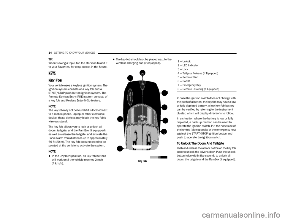
Key Fob
In case the ignition switch does not change with
the push of a button, the key fob may have a low
or fully depleted battery. A low key fob battery
can be verified by referring to the instrument
cluster, which will display directions to follow.
In a situation where the battery is low or fully
depleted, a back up method can be used to
operate the ignition switch. Put the nose side of
the key fob (side opposite of the emergency key)
against the START/STOP ignition button and
push to operate the ignition switch.
To Unlock The Doors And Tailgate
Push and release the unlock button on the key fob
once to unlock the driver’s door. Push the unlock
button twice within five seconds to unlock all
doors, the tailgate and the RamBox (if equipped).
1 — Unlock
2 — LED Indicator
3 — Lock
4 — Tailgate Release (If Equipped)
5 — Remote Start
6 — PANIC
7 — Emergency Key
8 — Remote Lowering (If Equipped)
20_DJD2_OM_EN_USC_t.book Page 14
Page 20 of 568

18GETTING TO KNOW YOUR VEHICLE
(Continued)
START/STOP ignition button, with your foot
applied on the brake pedal, and push to operate
the ignition switch.
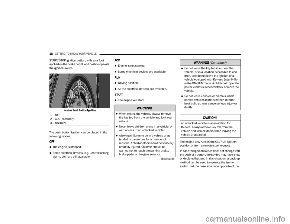
Keyless Push Button Ignition
The push button ignition can be placed in the
following modes:
OFF
The engine is stopped.
Some electrical devices (e.g. Central locking,
alarm, etc.) are still available. ACC
Engine is not started.
Some electrical devices are available.
RUN
Driving position.
All the electrical devices are available.
START
The engine will start.
The engine only runs in the ON/RUN ignition
position or from a remote start request.
In case the ignition switch does not change with
the push of a button, the key fob may have a low
or depleted battery. In this situation, a back up
method can be used to operate the ignition
switch. Put the nose side (side opposite of the
1 — OFF
2 — ACC (Accessory)
3 — ON/RUN
WARNING!
When exiting the vehicle, always remove
the key fob from the vehicle and lock your
vehicle.
Never leave children alone in a vehicle, or
with access to an unlocked vehicle.
Allowing children to be in a vehicle unat-
tended is dangerous for a number of
reasons. A child or others could be seriously
or fatally injured. Children should be
warned not to touch the parking brake,
brake pedal or the gear selector.
Do not leave the key fob in or near the
vehicle, or in a location accessible to chil -
dren, and do not leave the ignition of a
vehicle equipped with Keyless Enter-N-Go
in the ON/RUN mode. A child could operate
power windows, other controls, or move the
vehicle.
Do not leave children or animals inside
parked vehicles in hot weather. Interior
heat build-up may cause serious injury or
death.
CAUTION!
An unlocked vehicle is an invitation for
thieves. Always remove key fob from the
vehicle and lock all doors when leaving the
vehicle unattended.
WARNING! (Continued)
20_DJD2_OM_EN_USC_t.book Page 18
Page 21 of 568

GETTING TO KNOW YOUR VEHICLE19
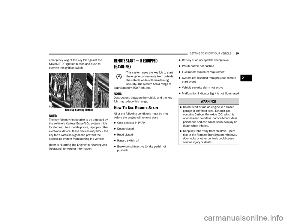
emergency key) of the key fob against the
START/STOP ignition button and push to
operate the ignition switch.
Back Up Starting Method
NOTE:
The key fob may not be able to be detected by
the vehicle’s Keyless Enter-N-Go system if it is
located next to a mobile phone, laptop or other
electronic device; these devices may block the
key fob’s wireless signal and prevent the
keyless-go system from starting the vehicle.
Refer to "Starting The Engine" in "Starting And
Operating" for further information.REMOTE START — IF EQUIPPED
(GASOLINE)
This system uses the key fob to start
the engine conveniently from outside
the vehicle while still maintaining
security. The system has a range of
approximately 300 ft (91 m).
NOTE:
Obstructions between the vehicle and the key
fob may reduce this range.
HOW TO USE REMOTE START
All of the following conditions must be met
before the engine will remote start:
Gear selector in PARK
Doors closed
Hood closed
Hazard switch off
Brake switch inactive (brake pedal not
pushed)
Battery at an acceptable charge level
PANIC button not pushed
Fuel meets minimum requirement
System not disabled from previous remote
start event
Vehicle security alarm not active
Malfunction Indicator Light is not illuminated
WARNING!
Do not start or run an engine in a closed
garage or confined area. Exhaust gas
contains Carbon Monoxide (CO) which is
odorless and colorless. Carbon Monoxide is
poisonous and can cause serious injury or
death when inhaled.
Keep key fobs away from children. Opera -
tion of the Remote Start System, windows,
door locks or other controls could cause
serious injury or death.
2
20_DJD2_OM_EN_USC_t.book Page 19
Page 117 of 568

GETTING TO KNOW YOUR INSTRUMENT PANEL115
Up Arrow Button
Push and release the up arrow
button to scroll upward through the
main menu items, submenu
screen, and vehicle settings.
Down Arrow Button
Push and release the down arrow
button to scroll downward through
the main menu items, submenu
screen, and vehicle settings.
Right Arrow Button
Push and release the right arrow
button to access/select the infor -
mation screens or submenu
screens of a main menu item. Push
and hold the right arrow button for two
seconds to reset displayed/selected features
that can be reset.
Left Arrow Button
Push and release the left arrow
button to access/select the infor -
mation screens, submenu screens
of a main menu item, or to return to
the main menu.
OIL LIFE RESET
Your vehicle is equipped with an engine oil
change indicator system. The “Oil Change
Required” message will display in the
instrument cluster display after a single chime
has sounded, to indicate the next scheduled oil
change interval. The engine oil change indicator
system is duty cycle based, which means the
engine oil change interval may fluctuate,
dependent upon your personal driving style.
NOTE:
Use the steering wheel instrument cluster
display controls for the following procedure.
Oil Life Reset Procedure
1. Without pushing the brake pedal, push the ENGINE START/STOP button and place the
ignition to the ON/RUN position (do not
start the engine).
2. Push and release the down arrow button to
scroll downward through the main menu to
“Vehicle Info.”
3. Push and release the right arrow button to
access the ”Vehicle Info” screen, then scroll
up or down to select “Oil Life.” 4. Push and hold the
right arrow button to
select “Reset”.
5. Push and release the down arrow button to
select “Yes,” then push and release the
right arrow button to reset the Oil Life to
100%.
6. Push and release the up arrow button to exit
the instrument cluster display screen.
Secondary Method Of Resetting Engine Oil Life
1. Without pressing the brake pedal, push the ENGINE START/STOP button and place the
ignition to the ON/RUN position (do not
start the engine).
2. Fully press the accelerator pedal, slowly, three times within ten seconds.
3. Without pushing the brake pedal, push the ENGINE START/STOP button once to return
the ignition to the OFF/LOCK position.
NOTE:
If the indicator message illuminates when you
start the vehicle, the oil change indicator
system did not reset. If necessary, repeat this
procedure.
3
20_DJD2_OM_EN_USC_t.book Page 115
Page 216 of 568

214STARTING AND OPERATING
KEYLESS ENTER-N-GO — IGNITION
This feature allows the driver to operate the
ignition switch with the push of a button, as long
as the Remote Start/Keyless Enter-N-Go key
fob is in the passenger compartment.
NORMAL STARTING USING ENGINE
START/S TOP B
UTTON
To Turn On The Engine Using The ENGINE
START/STOP Button
1. The transmission must be in PARK.
2. Press and hold the brake pedal while pushing the ENGINE START/STOP button
once.
3. The system takes over and attempts to start the vehicle. If the vehicle fails to start, the
starter will disengage automatically after
10 seconds.
4. If you wish to stop the cranking of the engine prior to the engine starting, push the
ENGINE START/STOP button again.
NOTE:
Normal starting of either a cold or a warm
engine is obtained without pumping or pressing
the accelerator pedal. To Turn Off The Engine Using ENGINE START/
STOP Button
1. Place the gear selector in PARK, then push
and release the ENGINE START/STOP
button.
2. The ignition will return to the OFF mode.
3. If the gear selector is not in PARK, the ENGINE START/STOP button must be held
for two seconds or three short pushes in a
row with the vehicle speed above 5 mph
(8 km/h) before the engine will shut off. The
ignition will remain in the ACC mode until
the gear selector is in PARK and the button
is pushed twice to the OFF mode.
4. If the gear selector is not in PARK and the ENGINE START/STOP button is pushed
once with the vehicle speed above 5 mph
(8 km/h), the instrument cluster will display
a “Vehicle Not In Park ” message and the
engine will remain running. Never leave a
vehicle out of the PARK position, or it could
roll.
NOTE:
If the gear selector is not in PARK, and the
ENGINE START/STOP button is pushed once with the vehicle speed below 5 mph (8 km/h),
the engine will shut off and the ignition will
remain in the ACC position. If vehicle speed
drops below 1.2 mph (1.9 km/h), the vehicle
may AutoPark. See AutoPark section for further
details.
ENGINE START/STOP Button Functions — With
Driver’s Foot OFF The Brake Pedal (In PARK Or
NEUTRAL Position)
The ENGINE START/STOP button operates
similar to an ignition switch. It has three modes:
OFF, ACC, and RUN. To change the ignition
modes without starting the vehicle and use the
accessories, follow these directions:
1. Start with the ignition in the OFF mode.
2. Push the ENGINE START/STOP button once
to place the ignition to the ACC mode.
3. Push the ENGINE START/STOP button a second time to place the ignition to the RUN
mode.
4. Push the ENGINE START/STOP button a third time to return the ignition to the OFF
mode.
20_DJD2_OM_EN_USC_t.book Page 214
Page 220 of 568

218STARTING AND OPERATING
Tip Start Feature
Do not press the accelerator. Cycle the ignition
switch briefly to the START position and release
it. The starter motor will continue to run and will
automatically disengage when the engine is
running.
KEYLESS ENTER-N-GO — IGNITION
This feature allows the driver to operate the
ignition switch with the push of a button, as long
as the Remote Start/Keyless Enter-N-Go key
fob is in the passenger compartment.
Normal Starting
Using The ENGINE START/STOP Button
1. The transmission must be in PARK or NEUTRAL.
2. Press and hold the brake pedal while pushing the ENGINE START/STOP button
once.
3. The system takes over and attempts to start the vehicle. If the vehicle fails to start, the
starter will disengage automatically after
25 seconds. 4. If you wish to stop the cranking of the
engine prior to the engine starting, remove
your foot from the brake pedal and push the
ENGINE START/STOP button again.
NOTE:
Normal starting of either a cold or a warm
engine is obtained without pumping or
pressing the accelerator pedal.
Under cold weather conditions, the engine
may not immediately crank if the “Wait To
Start” telltale is illuminated. This is normal
operation. For vehicles equipped with
Keyless Enter-N-Go, the vehicle will automat -
ically crank when the “Wait To Start” time has
elapsed. See the section “Starting Procedure
— Engine Manifold Air Temperature 0°F to
66°F (-18°C to 19°C)” for more information.
To Turn Off The Engine Using ENGINE START/
STOP Button
1. Place the gear selector in PARK, then push and release the ENGINE START/STOP
button.
2. The ignition will return to the OFF mode. 3. If the gear selector is not in PARK and the
ENGINE START/STOP button is pushed
once, the instrument cluster will display a
“Vehicle Not In Park” message and the
engine will remain running. Never leave a
vehicle out of the PARK position, or it could
roll.
4. If the gear selector is in NEUTRAL, and the vehicle speed below 5 mph (8 km/h),
pushing the ENGINE START/STOP button
once will turn the engine off. The ignition will
remain in the ACC mode.
5. If the vehicle speed is above 5 mph (8 km/h), the ENGINE START/STOP button must be
held for two seconds (or three short pushes
in a row) to turn the engine off. The ignition
will remain in the ACC mode (NOT the OFF
mode) if the engine is turned off when the
transmission is not in PARK.
NOTE:
If the ignition is left in the ACC or ON/RUN
(engine not running) mode and the transmis -
sion is in PARK, the system will automatically
time out after 30 minutes of inactivity and the
ignition return to the OFF mode.
20_DJD2_OM_EN_USC_t.book Page 218
Page 221 of 568

STARTING AND OPERATING219
ENGINE START/STOP Button Functions — With
Driver’s Foot OFF The Brake Pedal (In PARK Or
NEUTRAL Position)
The ENGINE START/STOP button operates
similar to an ignition switch. It has three
positions, OFF, ACC, RUN. To change the
ignition switch positions without starting the
vehicle and use the accessories follow these
steps:
1. Starting with the ignition in the OFF
position:
2. Push the ENGINE START/STOP button once to change the ignition to the ACC position.
3. Push the ENGINE START/STOP button a second time to change the ignition to the
RUN position.
4. Push the ENGINE START/STOP button a third time to return the ignition to the OFF
position.Keyless Enter-N-Go Starting Procedure —
Engine Manifold Air Temperature 0° F To
66° F (–18° C to 19° C)
NOTE:
The temperature displayed in the instrument
cluster does not necessarily reflect the engine
manifold air temperature. Refer to “Instrument
Cluster Display” in “Getting To Know Your
Instrument Panel” for further information.
When engine temperatures fall below 66°F
(19°C) the “Wait To Start” telltale will remain on
indicating the intake air heater system is active.
Follow the steps in the “Normal Starting”
procedure except:
1. Pushing the ENGINE START/STOP button with the driver’s foot on the brake will
move the ignition from OFF or ACC to RUN,
and will illuminate the “Wait To Start”
telltale. The engine will not immediately
crank, this is normal operation.
2. The “Wait To Start” telltale will remain on for a period of time that varies depending on
the engine temperature. 3. While the “Wait to Start” telltale is on, the
instrument cluster will additionally display a
gauge or bar whose initial length represents
the full “Wait to Start” time period. Its length
will decrease until it disappears when the
“Wait to Start” time has elapsed.
4. After the engine “Wait To Start” telltale goes off, the engine will automatically crank.
CAUTION!
If the “Water in Fuel Indicator Light” remains
on, DO NOT START the engine before you
drain the water from the fuel filters to avoid
engine damage. Refer to “Draining Fuel/
Water Separator Filter” in “Servicing And
Maintenance” for further information.
CAUTION!
Do not crank engine for more than 25 seconds
at a time or starter motor damage may result.
Turn the ignition switch to the OFF position and
wait at least two minutes for the starter to cool
before repeating start procedure.
5
20_DJD2_OM_EN_USC_t.book Page 219
Page 235 of 568

STARTING AND OPERATING233
(Continued)
NOTE:
For optimum braking power it is recommended
to use the exhaust brake while in TOW/HAUL
mode.
The exhaust brake feature can also be used to
reduce the engine warm up time. To use the
exhaust brake as a warm-up device, the vehicle
must be stopped or moving less than 5 mph
(8 km/h), the "Exhaust Brake Indicator" must be
on, and the coolant temperature must be below
180°F (82°C) and ambient temperature below
60°F (16°C). Automatic “Smart” Exhaust Brake
Automatic “Smart” Exhaust Brake technology
delivers smoother, less aggressive exhaust
braking characteristics during downhill
descents. Although it can apply full exhaust
braking force if needed, Automatic “Smart”
Exhaust Brake may not apply obvious braking if
the vehicle speed is not increasing. Automatic
“Smart” Exhaust Brake is intended to maintain
vehicle speed, while Full Exhaust Brake is
intended to reduce vehicle speed.
Automatic “Smart” Exhaust Brake can be
enabled by pushing the exhaust brake button
(on the center stack) again anytime after the
normal Full Exhaust Brake has been turned on.
The “Exhaust Brake Indicator” in the instrument
cluster display will change from Yellow to Green
when Automatic “Smart” Exhaust Brake is
enabled. Pushing the exhaust brake button
again will toggle the exhaust brake mode to off.
AUTOMATIC TRANSMISSION WARNING!
Do not use the exhaust brake feature when
driving in icy or slippery conditions as the
increased engine braking can cause the rear
wheels to slide and the vehicle to swing
around with the possible loss of vehicle
control, which may cause an accident
possibly resulting in personal injury or death.
CAUTION!
Use of aftermarket exhaust brakes is not
recommended and could lead to engine
damage
WARNING!
Never use the PARK position as a substi
-
tute for the parking brake. Always apply the
parking brake fully when exiting the vehicle
to guard against vehicle movement and
possible injury or damage.
Your vehicle could move and injure you and
others if it is not in PARK. Check by trying to
move the transmission gear selector out of
PARK with the brake pedal released. Make
sure the transmission is in PARK before
exiting the vehicle.
The transmission may not engage PARK if
the vehicle is moving. Always bring the
vehicle to a complete stop before shifting to
PARK, and verify that the transmission gear
position indicator solidly indicates PARK (P)
without blinking. Ensure that the vehicle is
completely stopped, and the PARK position
is properly indicated, before exiting the
vehicle.
5
20_DJD2_OM_EN_USC_t.book Page 233
Page 250 of 568

248STARTING AND OPERATING
NOTE:
The transfer case NEUTRAL button is located in
the center of the 4WD Control Switch and is
pushed by using a ballpoint pen or similar
object. The transfer case NEUTRAL position is to
be used for recreational towing only. Refer to
“Recreational Towing” in “Starting And Oper -
ating” for further information.
Transfer Case Position Indicator Lights
The Transfer Case Position Indicator Lights
(4WD HIGH and 4WD LOW) are located in the
instrument cluster and indicate the current and
desired transfer case selection. When you
select a different transfer case position, the
indicator lights will do the following:
If All Of The Following Shift Conditions Are Met:
1. The current position indicator light will turn off.
2. The selected position indicator light will flash until the transfer case completes the
shift.
3. When the shift is complete, the indicator light for the selected position will stop
flashing and remain on. If One Or More Of The Following Shift Conditions
Are Not Met:
1. The indicator light for the current position
will remain on.
2. The newly selected position indicator light will continue to flash.
3. The transfer case will not shift.
NOTE:
Before retrying a selection, make certain that all
the necessary requirements for selecting a new
transfer case position have been met. To retry the
selection, push the current position, wait five
seconds, and retry selection. To find the shift
requirements, refer to the “Shifting Procedure”
for your transfer case, located in this section.
The “SVC 4WD Warning Light” monitors the
electronic shift four-wheel drive system. If this
light remains on after engine start up or
illuminates during driving, it means that the
four-wheel drive system is not functioning
properly and that service is required.
NOTE:
Do not attempt to make a shift while only the
front or rear wheels are spinning. This could
cause damage to driveline components. When operating your vehicle in 4WD LOW, the
engine speed is approximately three times that
of the 2WD or 4WD HIGH positions at a given
road speed. Take care not to overspeed the
engine and do not exceed 25 mph (40 km/h).
Proper operation of four-wheel drive vehicles
depends on tires of equal size, type and
circumference on each wheel. Any difference in
tire size can cause damage to the drivetrain.
Because four-wheel drive provides improved
traction, there is a tendency to exceed safe
turning and stopping speeds. Do not go faster
than road conditions permit.
Shifting Procedure
NOTE:
If any of the requirements to select a new
transfer case position have not been met, the
transfer case will not shift. The position indi
-
cator light for the previous position will
remain on and the newly selected position
indicator light will continue to flash until all
the requirements for the selected position
have been met.
If all the requirements to select a new
transfer case position have been met, the
20_DJD2_OM_EN_USC_t.book Page 248