charging Ram 3500 Chassis Cab 2020 Owner's Manual
[x] Cancel search | Manufacturer: RAM, Model Year: 2020, Model line: 3500 Chassis Cab, Model: Ram 3500 Chassis Cab 2020Pages: 516, PDF Size: 29.24 MB
Page 5 of 516
3
EXTERIOR LIGHTS ...............................................44 Multifunction Lever ...................................... 44
Headlight Switch .......................................... 44
Daytime Running Lights (DRLs) ................. 45
High/Low Beam Switch ............................... 45
Automatic High Beam Headlamp
Control — If Equipped .................................. 45 Flash-To-Pass ............................................. 46
Automatic Headlights — If Equipped .......... 46
Parking Lights And Panel Lights ................. 46
Directional LED Headlamp System —
If Equipped ................................................... 46 Headlights On With Wipers (Available With
Automatic Headlights Only) ......................... 46 Headlight Delay ............................................ 47
Lights-On Reminder ..................................... 47
Front Fog Lights — If Equipped .................. 47
Turn Signals ............................................. 47
Lane Change Assist — If Equipped ............. 47
Cargo Lights/Trailer Spotter Lights —
If Equipped ................................................... 47 Battery Saver................................................ 48
INTERIOR LIGHTS ................................................48
Courtesy Lights ............................................ 48
Illuminated Entry ......................................... 49
WINDSHIELD WIPERS AND WASHERS ............50
Windshield Wipers ..................................... 50
Rain Sensing Wipers — If Equipped ........... 51 CLIMATE CONTROLS ........................................... 51
Manual Climate Control Overview ............ 52
Automatic Climate Control Overview .......... 55
Climate Control Functions........................... 62
Automatic Temperature Control (ATC) ...... 62
Operating Tips ............................................. 63
WINDOWS ............................................................ 64
Power Windows — If Equipped .................... 64
Wind Buffeting ............................................ 66
HOOD .................................................................... 66
To Open The Hood ...................................... 66
To Close The Hood ....................................... 67
GARAGE DOOR OPENER — IF EQUIPPED ........ 67
Before You Begin Programming
HomeLink® .................................................. 68 Canadian/Gate Operator Programming ..... 70
Using HomeLink®........................................ 71
Security......................................................... 71
Troubleshooting Tips ................................... 71
General Information .................................... 72
INTERNAL EQUIPMENT ........................................ 72
Storage ......................................................... 72
Cupholders .................................................. 77
Electrical Power Outlets ............................ 78
Power Inverter — If Equipped ..................... 80
Wireless Charging Pad — If Equipped ........ 81
Overhead Sunglass Storage ....................... 81
GETTING TO KNOW YOUR INSTRUMENT PANEL
BASE / MIDLINE INSTRUMENT CLUSTER..........82Base / Midline Instrument Cluster
Descriptions ................................................. 83
PREMIUM INSTRUMENT CLUSTER .....................85
Premium Instrument Cluster
Descriptions ................................................. 86
DIESEL INSTRUMENT CLUSTER .........................87
DIESEL INSTRUMENT CLUSTER ................ 88
INSTRUMENT CLUSTER .......................................90
Diesel INSTRUMENT CLUSTER .................. 91
INSTRUMENT CLUSTER DISPLAY .......................92
Instrument Cluster Display Controls .......... 92
Oil Life Reset ............................................... 93
Display Menu Items ..................................... 94
Diesel Messages And Warnings —
6.7L Cummins Diesel Engine ................... 103 Battery Saver On/Battery Saver Mode
Message — Electrical Load Reduction Actions
— If Equipped .......................................... 107
WARNING LIGHTS AND MESSAGES ............... 108
Red Warning Lights ................................... 108
Yellow Warning Lights ............................... 111Yellow Indicator Lights .............................. 115
Green Indicator Lights ............................... 116White Indicator Lights ............................... 117Blue Indicator Lights ................................. 118
2020_RAM_CHASSIS_CAB_OM_USA=GUID-6C67832B-7839-4CCF-BEFC-CDF988F949EA=1=en=.book Page 3
Page 15 of 516
GETTING TO KNOW YOUR VEHICLE13
TIP:
When viewing a topic, tap the star icon to add it
to your Favorites, for easy access in the future.
KEYS
Key Fob
Your vehicle uses a keyless ignition system. The
ignition system consists of a key fob with
Remote Keyless Entry (RKE) and a START/STOP
push button ignition system. The Remote
Keyless Entry (RKE) system (if equipped)
consists of a key fob and Keyless Enter-N-Go
feature.
NOTE:
The key fob may not be found if it is located next
to a mobile phone, laptop or other electronic
device; these devices may block the key fob’s
wireless signal.
If the vehicle is equipped with remote power
door locks, the key fob allows you to lock or
unlock all doors, as well as activate the Panic
Alarm, from distances up to approximately 66 ft
(20 m). The key fob does not need to be pointed
at the vehicle to activate the system. NOTE:
In the ON/RUN position, all key fob buttons
will work until the vehicle reaches 2 mph
(4 km/h).
The key fob should not be placed next to the
wireless charging pad (if equipped).
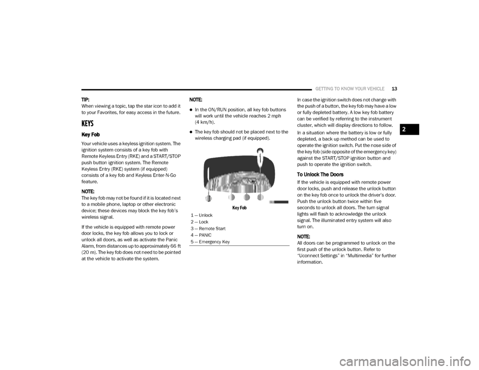
Key Fob
In case the ignition switch does not change with
the push of a button, the key fob may have a low
or fully depleted battery. A low key fob battery
can be verified by referring to the instrument
cluster, which will display directions to follow.
In a situation where the battery is low or fully
depleted, a back up method can be used to
operate the ignition switch. Put the nose side of
the key fob (side opposite of the emergency key)
against the START/STOP ignition button and
push to operate the ignition switch.
To Unlock The Doors
If the vehicle is equipped with remote power
door locks, push and release the unlock button
on the key fob once to unlock the driver’s door.
Push the unlock button twice within five
seconds to unlock all doors. The turn signal
lights will flash to acknowledge the unlock
signal. The illuminated entry system will also
turn on.
NOTE:
All doors can be programmed to unlock on the
first push of the unlock button. Refer to
“Uconnect Settings” in “Multimedia” for further
information.
1 — Unlock
2 — Lock
3 — Remote Start
4 — PANIC
5 — Emergency Key
2
2020_RAM_CHASSIS_CAB_OM_USA=GUID-6C67832B-7839-4CCF-BEFC-CDF988F949EA=1=en=.book Page 13
Page 82 of 516
80GETTING TO KNOW YOUR VEHICLE
Power Inverter — If Equipped
If equipped, a 115 Volt (400 Watts Maximum)
inverter may be located inside the center
console towards the right hand side, just under
the Wireless Charging Pad (if equipped). This
inverter can power cellular phones, electronics
and other low power devices requiring power up
to 400 Watts. Certain high-end video game
consoles exceed this power limit, as will most
power tools.
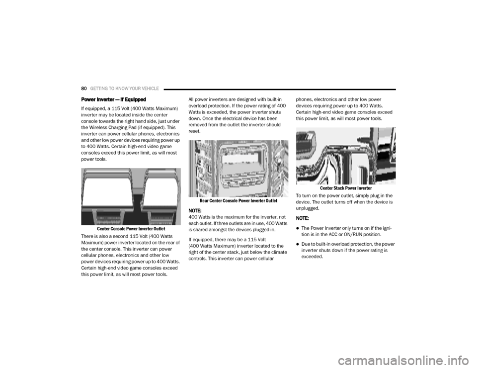
Center Console Power Inverter Outlet
There is also a second 115 Volt (400 Watts
Maximum) power inverter located on the rear of
the center console. This inverter can power
cellular phones, electronics and other low
power devices requiring power up to 400 Watts.
Certain high-end video game consoles exceed
this power limit, as will most power tools. All power inverters are designed with built-in
overload protection. If the power rating of 400
Watts is exceeded, the power inverter shuts
down. Once the electrical device has been
removed from the outlet the inverter should
reset.
Rear Center Console Power Inverter Outlet
NOTE:
400 Watts is the maximum for the inverter, not
each outlet. If three outlets are in use, 400 Watts
is shared amongst the devices plugged in.
If equipped, there may be a 115 Volt
(400 Watts Maximum) inverter located to the
right of the center stack, just below the climate
controls. This inverter can power cellular phones, electronics and other low power
devices requiring power up to 400 Watts.
Certain high-end video game consoles exceed
this power limit, as will most power tools.
Center Stack Power Inverter
To turn on the power outlet, simply plug in the
device. The outlet turns off when the device is
unplugged.
NOTE:
The Power Inverter only turns on if the igni -
tion is in the ACC or ON/RUN position.
Due to built-in overload protection, the power
inverter shuts down if the power rating is
exceeded.
2020_RAM_CHASSIS_CAB_OM_USA=GUID-6C67832B-7839-4CCF-BEFC-CDF988F949EA=1=en=.book Page 80
Page 83 of 516

GETTING TO KNOW YOUR VEHICLE81
Wireless Charging Pad — If Equipped
Wireless Charging Pad
Your vehicle may be equipped with a 15W 3A Qi
wireless charging pad located inside of the
center console just below the CD player (if
equipped). This charging pad is designed to wirelessly charge your Qi enabled mobile
phone. Qi is a standard that uses magnetic
induction to transfer power to your mobile
device.
Your mobile phone must be designed for Qi
wireless charging. If the phone is not equipped
with Qi wireless charging functionality, an after
-
market sleeve or a specialized back plate can
be purchased from your mobile phone provider
or an local electronics retailer. Please see your
phone’s owner’s manual for further informa -
tion.
The wireless charging pad is equipped with an
anti-slip mat, an adjustable cradle to hold your
mobile phone in place and an LED indicator
light.
Overhead Sunglass Storage
At the front of the overhead console, a compart -
ment is provided for the storage of one pair of
sunglasses.
From the closed position, push the door latch to
open the compartment.
Overhead Sunglass Door
The door will slowly rotate to the full open posi -
tion.WARNING!
To avoid serious injury or death:
Do not insert any objects into the recepta -
cles.
Do not touch with wet hands.
Close the lid when not in use.
If this outlet is mishandled, it may cause an
electric shock and failure.
CAUTION!
The key fob should not be placed on the
charging pad or within 15 cm (150 mm) of it.
Doing so can cause excessive heat buildup
and damage to the fob. Placing the fob in
close proximity of the charging pad blocks the
fob from being detected by the vehicle and
prevents the vehicle from starting.
2
2020_RAM_CHASSIS_CAB_OM_USA=GUID-6C67832B-7839-4CCF-BEFC-CDF988F949EA=1=en=.book Page 81
Page 109 of 516

GETTING TO KNOW YOUR INSTRUMENT PANEL107
Battery Saver On/Battery Saver Mode
Message — Electrical Load Reduction
Actions — If Equipped
This vehicle is equipped with an Intelligent
Battery Sensor (IBS) to perform additional moni-
toring of the electrical system and status of the
vehicle battery.
In cases when the IBS detects charging system
failure, or the vehicle battery conditions are
deteriorating, electrical load reduction actions
will take place to extend the driving time and
distance of the vehicle. This is done by reducing
power to or turning off non-essential electrical
loads.
Load reduction is only active when the engine is
running. It will display a message if there is a
risk of battery depletion to the point where the
vehicle may stall due to lack of electrical supply,
or will not restart after the current drive cycle.
When load reduction is activated, the message
“Battery Saver On Some Systems May Have
Reduced Power” will appear in the instrument
cluster.
These messages indicate the vehicle battery
has a low state of charge and continues to lose
electrical charge at a rate that the charging
system cannot sustain. NOTE:
The charging system is independent from
load reduction. The charging system
performs a diagnostic on the charging
system continuously.
If the Battery Charge Warning Light is on it
may indicate a problem with the charging
system. Refer to “Battery Charge Warning
Light” in “Getting To Know Your Instrument
Panel” for further information.
The electrical loads that may be switched off (if
equipped), and vehicle functions which can be
affected by load reduction:
Heated Seats/Vented Seats/Heated Wheel
Rear Defroster And Heated Mirrors
HVAC System
115 Volt AC Power Inverter System
Audio and Telematics System Loss of the battery charge may indicate one or
more of the following conditions:
The charging system cannot deliver enough
electrical power to the vehicle system
because the electrical loads are larger than
the capability of charging system. The
charging system is still functioning properly.
Turning on all possible vehicle electrical
loads (e.g. HVAC to max settings, exterior and
interior lights, overloaded power outlets
+12 Volts, 115 Volt AC, USB ports) during
certain driving conditions (city driving,
towing, frequent stopping).
Installing options like additional lights,
upfitter electrical accessories, audio
systems, alarms and similar devices.
Unusual driving cycles (short trips separated
by long parking periods).
The vehicle was parked for an extended
period of time (weeks, months).
The battery was recently replaced and was
not charged completely.
3
2020_RAM_CHASSIS_CAB_OM_USA=GUID-6C67832B-7839-4CCF-BEFC-CDF988F949EA=1=en=.book Page 107
Page 112 of 516

110GETTING TO KNOW YOUR INSTRUMENT PANEL
Vehicle Security Warning Light — If Equipped
This light will flash at a fast rate for
approximately 15 seconds when the
vehicle security alarm is arming, and
then will flash slowly until the vehicle
is disarmed.
Engine Coolant Temperature Warning Light
This warning light warns of an over -
heated engine condition. If the engine
coolant temperature is too high, this
indicator will illuminate and a single
chime will sound. If the temperature reaches
the upper limit, a continuous chime will sound
for four minutes or until the engine is able to
cool, whichever comes first.
If the light turns on while driving, safely pull over
and stop the vehicle. If the A/C system is on,
turn it off. Also, shift the transmission into
NEUTRAL and idle the vehicle. If the tempera -
ture reading does not return to normal, turn the
engine off immediately and call for service.
Refer to “If Your Engine Overheats” in “In Case
Of Emergency” for further information.
Battery Charge Warning Light
This warning light will illuminate when
the battery is not charging properly. If
it stays on while the engine is running,
there may be a malfunction with the
charging system. Contact an authorized dealer
as soon as possible.
This indicates a possible problem with the elec -
trical system or a related component.
Oil Pressure Warning Light
This warning light will illuminate to
indicate low engine oil pressure. If the
light turns on while driving, stop the
vehicle, shut off the engine as soon as
possible, and contact an authorized dealer. A
chime will sound when this light turns on.
Do not operate the vehicle until the cause is
corrected. This light does not indicate how
much oil is in the engine. The engine oil level
must be checked under the hood.
Oil Temperature Warning Light
This warning light will illuminate to
indicate the engine oil temperature is
high. If the light turns on while driving,
stop the vehicle and shut off the
engine as soon as possible. Wait for oil
temperature to return to normal levels.
Electronic Throttle Control (ETC) Warning
Light
This warning light will illuminate to
indicate a problem with the Electronic
Throttle Control (ETC) system. If a
problem is detected while the vehicle
is running, the light will either stay on or flash
depending on the nature of the problem. Cycle
the ignition when the vehicle is safely and
completely stopped and the transmission is
placed in the PARK position. The light should
turn off. If the light remains on with the vehicle
running, your vehicle will usually be drivable;
however, see an authorized dealer for service
as soon as possible.
NOTE:
This light may turn on if the accelerator and
brake pedals are pressed at the same time.
2020_RAM_CHASSIS_CAB_OM_USA=GUID-6C67832B-7839-4CCF-BEFC-CDF988F949EA=1=en=.book Page 110
Page 322 of 516
320IN CASE OF EMERGENCY
Preparations For Jump Start
The battery in your vehicle is located in the front
of the engine compartment, behind the left
headlight assembly.
NOTE:
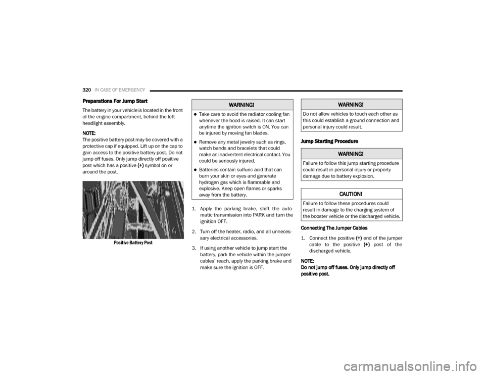
The positive battery post may be covered with a
protective cap if equipped. Lift up on the cap to
gain access to the positive battery post. Do not
jump off fuses. Only jump directly off positive
post which has a positive (+) symbol on or
around the post.
Positive Battery Post
1. Apply the parking brake, shift the auto
-
matic transmission into PARK and turn the
ignition OFF.
2. Turn off the heater, radio, and all unneces -
sary electrical accessories.
3. If using another vehicle to jump start the battery, park the vehicle within the jumper
cables’ reach, apply the parking brake and
make sure the ignition is OFF.
Jump Starting Procedure
Connecting The Jumper Cables
1. Connect the positive
(+) end of the jumper
cable to the positive (+)
post of the
discharged vehicle.
NOTE:
Do not jump off fuses. Only jump directly off
positive post.
WARNING!
Take care to avoid the radiator cooling fan
whenever the hood is raised. It can start
anytime the ignition switch is ON. You can
be injured by moving fan blades.
Remove any metal jewelry such as rings,
watch bands and bracelets that could
make an inadvertent electrical contact. You
could be seriously injured.
Batteries contain sulfuric acid that can
burn your skin or eyes and generate
hydrogen gas which is flammable and
explosive. Keep open flames or sparks
away from the battery.
WARNING!
Do not allow vehicles to touch each other as
this could establish a ground connection and
personal injury could result.
WARNING!
Failure to follow this jump starting procedure
could result in personal injury or property
damage due to battery explosion.
CAUTION!
Failure to follow these procedures could
result in damage to the charging system of
the booster vehicle or the discharged vehicle.
2020_RAM_CHASSIS_CAB_OM_USA=GUID-6C67832B-7839-4CCF-BEFC-CDF988F949EA=1=en=.book Page 320
Page 323 of 516
IN CASE OF EMERGENCY321
2. Connect the opposite end of the positive (+)
jumper cable to the positive (+) post of the
booster battery.
3. Connect the negative (-) end of the jumper
cable to the negative (-) post of the booster
battery.
4. Connect the opposite end of the negative (-)
jumper cable to a good engine ground
(exposed metal part of the discharged
vehicle’s engine) away from the battery and
the fuel injection system.
5. Start the engine in the vehicle that has the booster battery, let the engine idle a few
minutes, and then start the engine in the
vehicle with the discharged battery. 6. Once the engine is started, remove the
jumper cables in the reverse sequence.
Disconnecting The Jumper Cables
1. Disconnect the negative
(-)
end of the
jumper cable from the engine ground of
the vehicle with the discharged battery.
2. Disconnect the opposite end of the negative (-) jumper cable from the negative (-) post of
the booster battery.
3. Disconnect the positive (+) end of the
jumper cable from the positive (+) post of
the booster battery.
4. Disconnect the opposite end of the positive (+) jumper cable from the positive (+) post
of the vehicle with the discharged battery. If frequent jump starting is required to start your
vehicle you should have the battery and
charging system inspected at an authorized
dealer.
IF YOUR ENGINE OVERHEATS
In any of the following situations, you can
reduce the potential for overheating by taking
the appropriate action.
On the highways — slow down.
In city traffic — while stopped, place the trans
-
mission in NEUTRAL, but do not increase the
engine idle speed while preventing vehicle
motion with the brakes.
WARNING!
Do not connect the jumper cable to the
negative (-) post of the discharged battery.
The resulting electrical spark could cause the
battery to explode and could result in
personal injury. Only use the specific ground
point, do not use any other exposed metal
parts.
CAUTION!
Do not connect jumper cable to any of the
fuses on the positive battery terminal. The
resulting electrical current will blow the fuse.
CAUTION!
Accessories plugged into the vehicle power
outlets draw power from the vehicle’s battery,
even when not in use (i.e., cellular devices,
etc.). Eventually, if plugged in long enough
without engine operation, the vehicle’s
battery will discharge sufficiently to degrade
battery life and/or prevent the engine from
starting.
6
2020_RAM_CHASSIS_CAB_OM_USA=GUID-6C67832B-7839-4CCF-BEFC-CDF988F949EA=1=en=.book Page 321
Page 348 of 516

346SERVICING AND MAINTENANCE
After the engine has warmed up, operate the
defroster for a few minutes to reduce the possi -
bility of smearing or freezing the fluid on the
cold windshield. Windshield washer solution
used with water as directed on the container,
aids cleaning action, reduces the freezing point
to avoid line clogging, and is not harmful to
paint or trim.
Maintenance-Free Battery
Your vehicle is equipped with a mainte-
nance-free battery. You will never have to add
water, nor is periodic maintenance required.
NOTE:
Replacement batteries should both be of equal
capacity to prevent damage to the vehicle's
charging system.
Pressure Washing
WARNING!
Commercially available windshield washer
solvents are flammable. They could ignite and
burn you. Care must be exercised when filling
or working around the washer solution.
WARNING!
Battery fluid is a corrosive acid solution and
can burn or even blind you. Do not allow
battery fluid to contact your eyes, skin, or
clothing. Do not lean over a battery when
attaching clamps. If acid splashes in eyes
or on skin, flush the area immediately with
large amounts of water. Refer to “Jump
Starting Procedure” in “In Case Of Emer -
gency” for further information.
Battery gas is flammable and explosive.
Keep flame or sparks away from the
battery. Do not use a booster battery or any
other booster source with an output greater
than 12 Volts. Do not allow cable clamps to
touch each other.
Battery posts, terminals, and related acces -
sories contain lead and lead compounds.
Wash hands after handling.
CAUTION!
It is essential when replacing the cables on
the battery that the positive cable is
attached to the positive post and the nega -
tive cable is attached to the negative post.
Battery posts are marked positive (+) and
negative (-) and are identified on the battery
case. Cable clamps should be tight on the
terminal posts and free of corrosion.
If a “fast charger” is used while the battery
is in the vehicle, disconnect both vehicle
battery cables before connecting the
charger to the battery. Do not use a “fast
charger” to provide starting voltage.
CAUTION!
Cleaning the engine compartment with a high
pressure washer is not recommended.
Precautions have been taken to safeguard all
parts and connections however, the
pressures generated by these machines is
such that complete protection against water
ingress cannot be guaranteed.
2020_RAM_CHASSIS_CAB_OM_USA=GUID-6C67832B-7839-4CCF-BEFC-CDF988F949EA=1=en=.book Page 346
Page 415 of 516

MOPAR ACCESSORIES
Authentic Accessories By Mopar
In choosing Authentic Accessories you gain far more than expressive style, premium protection, or extreme entertainment, you also benefit from
enhancing your vehicle with accessories that have been thoroughly tested and factory-approved.
The following highlights just some of the many Authentic Ram Accessories by Mopar featuring a fit, finish, and functionality specifically for your Ram.
For the full line of Authentic Ram Accessories by Mopar, visit your local dealership or online at mopar.com for U.S. residents and mopar.ca for Cana-
dian residents.
NOTE:
All parts are subject to availability.
EXTERIOR:
• Tubular Side Steps • Front Air Deflectors• Side Window Deflectors
INTERIOR:
• Door Sill Guards • Leather Seats• Console Safe
• DOT Certified Emergency Kit • All-Weather Mats
ELECTRONICS:
• Wireless Charging Kit • Remote Start• Electronic Vehicle Tracking
8
2020_RAM_CHASSIS_CAB_OM_USA=GUID-6C67832B-7839-4CCF-BEFC-CDF988F949EA=1=en=.book Page 413
TECHNICAL
SPECIFICATIONS 413