Signal Ram 4500 Chassis Cab 2020 User Guide
[x] Cancel search | Manufacturer: RAM, Model Year: 2020, Model line: 4500 Chassis Cab, Model: Ram 4500 Chassis Cab 2020Pages: 516, PDF Size: 29.24 MB
Page 72 of 516

70GETTING TO KNOW YOUR VEHICLE
Reprogramming A Single HomeLink® Button
(Non-Rolling Code)
To reprogram a channel that has been previ -
ously trained, follow these steps:
1. Place the ignition in the ON/RUN position.
2. Press and hold the desired HomeLink® button until the indicator light begins to
flash after 20 seconds. Do not release the
button.
3. Without releasing the button, proceed with “Programming A Non-Rolling Code” step 2
and follow all remaining steps.
Canadian/Gate Operator Programming
For programming transmitters in Canada/
United States that require the transmitter
signals to “time-out” after several seconds of
transmission.
Canadian radio frequency laws require trans -
mitter signals to time-out (or quit) after several
seconds of transmission – which may not be
long enough for HomeLink® to pick up the
signal during programming. Similar to this
Canadian law, some U.S. gate operators are
designed to time-out in the same manner. It may be helpful to unplug the device during the
cycling process to prevent possible overheating
of the garage door or gate motor.
1. Place the ignition in the ON/RUN position.
2. Place the hand-held transmitter 1 to
3 inches (3 to 8 cm) away from the Home-
Link® button you wish to program while
keeping the HomeLink® indicator light in
view.
3. Continue to press and hold the HomeLink® button, while you press and release
(“cycle”) your hand-held transmitter every
two seconds until HomeLink® has success-
fully accepted the frequency signal. The
indicator light will flash slowly and then
rapidly when fully trained.
4. Watch for the HomeLink® indicator to change flash rates. When it changes, it is
programmed. It may take up to 30 seconds
or longer in rare cases. The garage door
may open and close while you are program -
ming. 5. Press and hold the programmed Home
-
Link® button and observe the indicator
light.
NOTE:
If the indicator light stays on constantly,
programming is complete and the garage
door/device should activate when the
HomeLink® button is pressed.
To program the two remaining HomeLink®
buttons, repeat each step for each
remaining button. DO NOT erase the chan -
nels.
If you unplugged the garage door opener/
device for programming, plug it back in at this
time.
Reprogramming A Single HomeLink® Button
(Canadian/Gate Operator)
To reprogram a channel that has been previ -
ously trained, follow these steps:
1. Place the ignition in the ON/RUN position.
2020_RAM_CHASSIS_CAB_OM_USA=GUID-6C67832B-7839-4CCF-BEFC-CDF988F949EA=1=en=.book Page 70
Page 110 of 516
108GETTING TO KNOW YOUR INSTRUMENT PANEL
The battery was discharged by an electrical
load left on when the vehicle was parked.
The battery was used for an extended period
with the engine not running to supply radio,
lights, chargers, +12 Volt portable appli-
ances like vacuum cleaners, game consoles
and similar devices.
What to do when an electrical load reduction
action message is present (“Battery Saver On”
or “Battery Saver Mode”)
During a trip:
Reduce power to unnecessary loads if
possible:
Turn off redundant lights (interior or exte -
rior).
Check what may be plugged in to power outlets +12 Volts, 115 Volt AC, USB ports.
Check HVAC settings (blower, tempera -
ture).
Check the audio settings (volume). After a trip:
Check if any aftermarket equipment was
installed (additional lights, upfitter electrical
accessories, audio systems, alarms) and
review specifications if any (load and Ignition
Off Draw currents).
Evaluate the latest driving cycles (distance,
driving time and parking time).
The vehicle should have service performed if
the message is still present during consecu
-
tive trips and the evaluation of the vehicle
and driving pattern did not help to identify the
cause.
WARNING LIGHTS AND MESSAGES
The warning/indicator lights will illuminate in
the instrument panel together with a dedicated
message and/or acoustic signal when appli -
cable. These indications are indicative and
precautionary and as such must not be consid -
ered as exhaustive. Always refer to the informa-
tion in this chapter in the event of a failure
indication. All active telltales will display first if
applicable. The system check menu may
appear different based upon equipment
options and current vehicle status. Some tell -
tales are optional and may not appear.
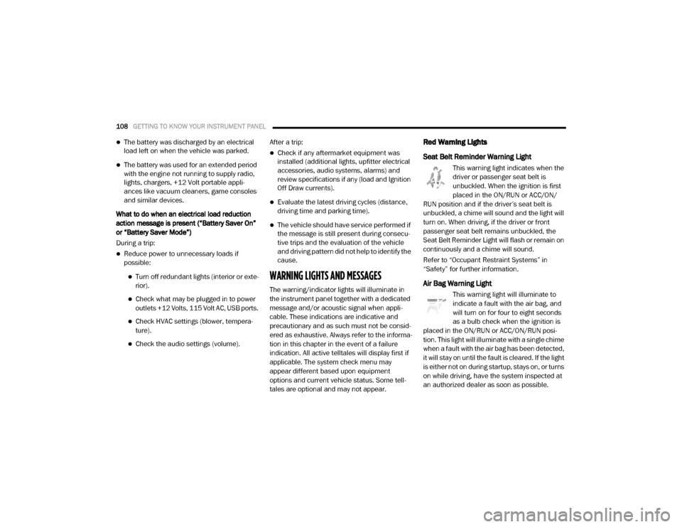
Red Warning Lights
Seat Belt Reminder Warning Light
This warning light indicates when the
driver or passenger seat belt is
unbuckled. When the ignition is first
placed in the ON/RUN or ACC/ON/
RUN position and if the driver’s seat belt is
unbuckled, a chime will sound and the light will
turn on. When driving, if the driver or front
passenger seat belt remains unbuckled, the
Seat Belt Reminder Light will flash or remain on
continuously and a chime will sound.
Refer to “Occupant Restraint Systems” in
“Safety” for further information.
Air Bag Warning Light
This warning light will illuminate to
indicate a fault with the air bag, and
will turn on for four to eight seconds
as a bulb check when the ignition is
placed in the ON/RUN or ACC/ON/RUN posi -
tion. This light will illuminate with a single chime
when a fault with the air bag has been detected,
it will stay on until the fault is cleared. If the light
is either not on during startup, stays on, or turns
on while driving, have the system inspected at
an authorized dealer as soon as possible.
2020_RAM_CHASSIS_CAB_OM_USA=GUID-6C67832B-7839-4CCF-BEFC-CDF988F949EA=1=en=.book Page 108
Page 116 of 516
114GETTING TO KNOW YOUR INSTRUMENT PANEL
Your vehicle has also been equipped with a
TPMS malfunction indicator to indicate when
the system is not operating properly. The TPMS
malfunction indicator is combined with the low
tire pressure telltale. When the system detects
a malfunction, the telltale will flash for approxi-
mately one minute and then remain continu -
ously illuminated. This sequence will continue
upon subsequent vehicle start-ups as long as
the malfunction exists. When the malfunction
indicator is illuminated, the system may not be
able to detect or signal low tire pressure as
intended. TPMS malfunctions may occur for a
variety of reasons, including the installation of
replacement or alternate tires or wheels on the
vehicle that prevent the TPMS from functioning
properly. Always check the TPMS malfunction
telltale after replacing one or more tires or
wheels on your vehicle to ensure that the
replacement or alternate tires and wheels allow
the TPMS to continue to function properly.
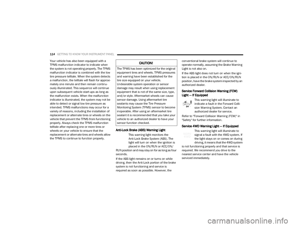
Anti-Lock Brake (ABS) Warning Light
This warning light monitors the
Anti-Lock Brake System (ABS). The
light will turn on when the ignition is
placed in the ON/RUN or ACC/ON/
RUN position and may stay on for as long as four
seconds.
If the ABS light remains on or turns on while
driving, then the Anti-Lock portion of the brake
system is not functioning and service is
required as soon as possible. However, the conventional brake system will continue to
operate normally, assuming the Brake Warning
Light is not also on.
If the ABS light does not turn on when the igni
-
tion is placed in the ON/RUN or ACC/ON/RUN
position, have the brake system inspected by an
authorized dealer.
Service Forward Collision Warning (FCW)
Light — If Equipped
This warning light will illuminate to
indicate a fault in the Forward Colli -
sion Warning System. Contact an
authorized dealer for service.
Refer to "Forward Collision Warning (FCW)" in
"Safety" for further information.
Service 4WD Warning Light — If Equipped
This warning light will illuminate to
signal a fault with the 4WD system. If
the light stays on or comes on during
driving, it means that the 4WD system
is not functioning properly and that service is
required. We recommend you drive to the
nearest service center and have the vehicle
serviced immediately.
CAUTION!
The TPMS has been optimized for the original
equipment tires and wheels. TPMS pressures
and warning have been established for the
tire size equipped on your vehicle.
Undesirable system operation or sensor
damage may result when using replacement
equipment that is not of the same size, type,
and/or style. Aftermarket wheels can cause
sensor damage. Using aftermarket tire
sealants may cause the Tire Pressure
Monitoring System (TPMS) sensor to become
inoperable. After using an aftermarket tire
sealant it is recommended that you take your
vehicle to an authorized dealer to have your
sensor function checked.
2020_RAM_CHASSIS_CAB_OM_USA=GUID-6C67832B-7839-4CCF-BEFC-CDF988F949EA=1=en=.book Page 114
Page 119 of 516
GETTING TO KNOW YOUR INSTRUMENT PANEL117
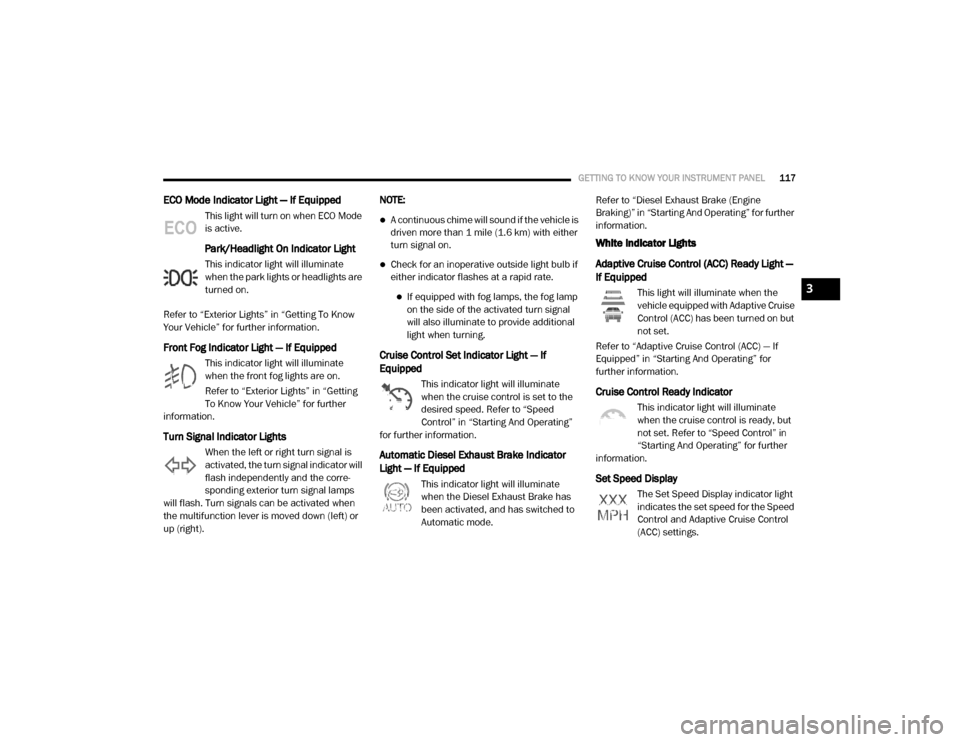
ECO Mode Indicator Light — If Equipped
This light will turn on when ECO Mode
is active.
Park/Headlight On Indicator Light
This indicator light will illuminate
when the park lights or headlights are
turned on.
Refer to “Exterior Lights” in “Getting To Know
Your Vehicle” for further information.
Front Fog Indicator Light — If Equipped
This indicator light will illuminate
when the front fog lights are on.
Refer to “Exterior Lights” in “Getting
To Know Your Vehicle” for further
information.
Turn Signal Indicator Lights
When the left or right turn signal is
activated, the turn signal indicator will
flash independently and the corre -
sponding exterior turn signal lamps
will flash. Turn signals can be activated when
the multifunction lever is moved down (left) or
up (right). NOTE:
A continuous chime will sound if the vehicle is
driven more than 1 mile (1.6 km) with either
turn signal on.
Check for an inoperative outside light bulb if
either indicator flashes at a rapid rate.
If equipped with fog lamps, the fog lamp
on the side of the activated turn signal
will also illuminate to provide additional
light when turning.
Cruise Control Set Indicator Light — If
Equipped
This indicator light will illuminate
when the cruise control is set to the
desired speed. Refer to “Speed
Control” in “Starting And Operating”
for further information.
Automatic Diesel Exhaust Brake Indicator
Light — If Equipped
This indicator light will illuminate
when the Diesel Exhaust Brake has
been activated, and has switched to
Automatic mode. Refer to “Diesel Exhaust Brake (Engine
Braking)” in “Starting And Operating” for further
information.
White Indicator Lights
Adaptive Cruise Control (ACC) Ready Light —
If Equipped
This light will illuminate when the
vehicle equipped with Adaptive Cruise
Control (ACC) has been turned on but
not set.
Refer to “Adaptive Cruise Control (ACC) — If
Equipped” in “Starting And Operating” for
further information.
Cruise Control Ready Indicator
This indicator light will illuminate
when the cruise control is ready, but
not set. Refer to “Speed Control” in
“Starting And Operating” for further
information.
Set Speed Display
The Set Speed Display indicator light
indicates the set speed for the Speed
Control and Adaptive Cruise Control
(ACC) settings.
3
2020_RAM_CHASSIS_CAB_OM_USA=GUID-6C67832B-7839-4CCF-BEFC-CDF988F949EA=1=en=.book Page 117
Page 137 of 516

SAFETY135
Should this occur, you should stop as soon as
possible and inflate the tires with a low pressure
condition (those in a different color in the instru -
ment cluster graphic) to the vehicle’s recom-
mended cold placard pressure inflation value
as shown in the "Inflate to XX" message. Once
the system receives the updated tire pressures,
the system will automatically update, the
graphic display in the instrument cluster will
return to its original color, and the “Tire Pres -
sure Monitoring Warning Light” will turn off. The
vehicle may need to be driven for up to
20 minutes above 15 mph (24 km/h) in order
for the TPMS to receive this information.
NOTE:
When filling warm tires, the tire pressure may
need to be increased up to an additional 4 psi
(28 kPa) above the recommended cold placard
pressure in order to turn the Tire Pressure Moni -
toring Warning Light off.Service TPMS Warning
If a system fault is detected, the “Tire Pressure
Monitoring Warning Light” will flash on and off
for 75 seconds and then remain on solid. In
addition, the instrument cluster will display a
"SERVICE TPM SYSTEM" message for a
minimum of five seconds and then display
dashes (- -) in place of the pressure value to indi -
cate which sensor is not being received.
If the ignition switch is cycled, this sequence will
repeat, providing the system fault still exists. If
the system fault no longer exists, the “Tire Pres -
sure Monitoring Warning Light” will no longer
flash, and the "SERVICE TPM SYSTEM" message
will no longer display, and a pressure value will
display in place of the dashes. A system fault
can occur due to any of the following:
Signal interference due to electronic devices
or driving next to facilities emitting the same
radio frequencies as the TPM sensors.
Installing aftermarket window tinting that
contains materials that may block radio wave
signals.
Accumulation of snow or ice around the
wheels or wheel housings.
Using tire chains on the vehicle.
Using wheels/tires not equipped with TPM
sensors.
A system fault may occur due to an incorrect
TPM sensor location condition. When a system
fault occurs due to an incorrect TPM sensor
location, the “Tire Pressure MonitoringWarning
Light” will flash on and off for 75 seconds and
then remain on solid. The system fault will also
sound a chime. In addition, the instrument
cluster will display a “Tire Pressure Temporarily
Unavailable” message in place of the tire pres -
sure display screen. If the ignition switch is
cycled, this sequence will repeat, providing the
system fault still exists. If the system fault no
longer exists, the “Tire Pressure Monitoring Indi -
cator Light” will no longer flash and the tire pres -
sure display screen will be displayed showing
the tire pressure values in the correct locations.
4
2020_RAM_CHASSIS_CAB_OM_USA=GUID-6C67832B-7839-4CCF-BEFC-CDF988F949EA=1=en=.book Page 135
Page 142 of 516

140SAFETY
Tire Pressure Information System (TPIS)
3500/4500/5500 Series Trucks
Your vehicle may be equipped with a Tire Pres -
sure Information System (TPIS).
The Tire Pressure Information System (TPIS)
uses wireless technology with wheel rim
mounted electronic sensors to transmit tire
pressure levels. Sensors mounted to each
wheel as part of the valve stem transmit tire
pressure readings to the receiver module.
NOTE:
It is particularly important for you to check the
tire pressure in all of the tires on your vehicle
monthly and to maintain the proper pressure.
The TPIS consists of the following components:
Receiver module
Four TPM sensors (Single Rear Wheel (SRW)
applications)
Six TPM sensors (Dual Rear Wheel (DRW)
applications)
Pressure display in the instrument cluster
The TPIS system will display all four (Single Rear
Wheel (SRW) applications) or six (Dual Rear
Wheel (DRW) applications) tire pressure values
in the instrument cluster display. If a system fault is detected, the instrument
cluster will display a "SERVICE TPM SYSTEM"
message for a minimum of five seconds and
then display dashes (- -) in place of the pressure
value to indicate which sensor is not being
received.
If the ignition switch is cycled, this sequence will
repeat, providing the system fault still exists. If
the system fault no longer exists, the "SERVICE
TPM SYSTEM" message will no longer be
displayed, and a pressure value will display in
place of the dashes. A system fault can occur
due to any of the following:
Signal interference due to electronic devices
or driving next to facilities emitting the same
radio frequencies as the TPM sensors.
Installing aftermarket window tinting that
contains materials that may block radio wave
signals.
Accumulation of snow or ice around the
wheels or wheel housings.
Using tire chains on the vehicle.
Using wheels/tires not equipped with TPM
sensors.
General Information
The following regulatory statement applies to all
Radio Frequency (RF) devices equipped in this
vehicle:
This device complies with Part 15 of the FCC
Rules and with Innovation, Science and
Economic Development Canada license-exempt
RSS standard(s). Operation is subject to the
following two conditions:
1. This device may not cause harmful interfer
-
ence, and
2. This device must accept any interference received, including interference that may
cause undesired operation.
Le présent appareil est conforme aux CNR
d`Innovation, Science and Economic Develop -
ment applicables aux appareils radio exempts
de licence. L'exploitation est autorisée aux deux
conditions suivantes:
1. l'appareil ne doit pas produire de brouil -
lage, et
2. l'utilisateur de l'appareil doit accepter tout brouillage radioélectrique subi, même si le
brouillage est susceptible d'en comprom -
ettre le fonctionnement.
2020_RAM_CHASSIS_CAB_OM_USA=GUID-6C67832B-7839-4CCF-BEFC-CDF988F949EA=1=en=.book Page 140
Page 144 of 516

142SAFETY
9. If the air bag system in this vehicle needs to
be modified to accommodate a disabled
person, refer to the “Customer Assistance”
section for customer service contact infor -
mation.
Seat Belt Systems
Buckle up even though you are an excellent
driver, even on short trips. Someone on the road
may be a poor driver and could cause a collision
that includes you. This can happen far away
from home or on your own street. Research has shown that seat belts save lives,
and they can reduce the seriousness of injuries
in a collision. Some of the worst injuries happen
when people are thrown from the vehicle. Seat
belts reduce the possibility of ejection and the
risk of injury caused by striking the inside of the
vehicle. Everyone in a motor vehicle should be
belted at all times.
Enhanced Seat Belt Use Reminder System
(BeltAlert)
Driver And Passenger BeltAlert — If Equipped
BeltAlert is a feature intended to remind the
driver and outboard front seat passenger (if
equipped with outboard front passenger seat
BeltAlert) to buckle their seat belts. The
BeltAlert feature is active whenever the ignition
switch is in the START or ON/RUN position.
Initial Indication
If the driver is unbuckled when the ignition
switch is first in the START or ON/RUN position,
a chime will signal for a few seconds. If the
driver or outboard front seat passenger (if
equipped with outboard front passenger seat
BeltAlert) is unbuckled when the ignition switch
is first in the START or ON/RUN position the Seat Belt Reminder Light will turn on and
remain on until both outboard front seat belts
are buckled. The outboard front passenger seat
BeltAlert is not active when an outboard front
passenger seat is unoccupied.
BeltAlert Warning Sequence
The BeltAlert warning sequence is activated
when the vehicle is moving above a specified
vehicle speed range and the driver or outboard
front seat passenger is unbuckled (if equipped
with outboard front passenger seat BeltAlert)
(the outboard front passenger seat BeltAlert is
not active when the outboard front passenger
seat is unoccupied). The BeltAlert warning
sequence starts by blinking the Seat Belt
Reminder Light and sounding an intermittent
chime. Once the BeltAlert warning sequence
has completed, the Seat Belt Reminder Light
will remain on until the seat belts are buckled.
The BeltAlert warning sequence may repeat
based on vehicle speed until the driver and
occupied outboard front seat passenger seat
belts are buckled. The driver should instruct all
occupants to buckle their seat belts.
WARNING!
Never place a rear-facing child restraint in
front of an air bag. A deploying passenger
front air bag can cause death or serious
injury to a child 12 years or younger,
including a child in a rear-facing child
restraint.
Never install a rear-facing child restraint in
the front seat of a vehicle. Only use a
rear-facing child restraint in the rear seat. If
the vehicle does not have a rear seat, do
not transport a rear-facing child restraint in
that vehicle.
2020_RAM_CHASSIS_CAB_OM_USA=GUID-6C67832B-7839-4CCF-BEFC-CDF988F949EA=1=en=.book Page 142
Page 155 of 516

SAFETY153
(Continued)
This vehicle may be equipped with a driver and/
or front passenger seat belt buckle switch that
detects whether the driver or front passenger
seat belt is buckled. The seat belt buckle switch
may adjust the inflation rate of the Advanced
Front Air Bags.
Front Air Bag Operation
Front Air Bags are designed to provide addi -
tional protection by supplementing the seat
belts. Front air bags are not expected to reduce
the risk of injury in rear, side, or rollover colli -
sions. The front air bags will not deploy in all
frontal collisions, including some that may
produce substantial vehicle damage — for
example, some pole collisions, truck under -
rides, and angle offset collisions.
On the other hand, depending on the type and
location of impact, front air bags may deploy in
crashes with little vehicle front-end damage but
that produce a severe initial deceleration. Because air bag sensors measure vehicle
deceleration over time, vehicle speed and
damage by themselves are not good indicators
of whether or not an air bag should have
deployed.
Seat belts are necessary for your protection in
all collisions, and also are needed to help keep
you in position, away from an inflating air bag.
When the ORC detects a collision requiring the
front air bags, it signals the inflator units. A large
quantity of non-toxic gas is generated to inflate
the front air bags.
The steering wheel hub trim cover and the
upper passenger side of the instrument panel
separate and fold out of the way as the air bags
inflate to their full size. The front air bags fully
inflate in less time than it takes to blink your
eyes. The front air bags then quickly deflate
while helping to restrain the driver and front
passenger.
WARNING!
No objects should be placed over or near
the air bag on the instrument panel or
steering wheel because any such objects
could cause harm if the vehicle is in a colli
-
sion severe enough to cause the air bag to
inflate.
Do not put anything on or around the air
bag covers or attempt to open them manu -
ally. You may damage the air bags and you
could be injured because the air bags may
no longer be functional. The protective
covers for the air bag cushions are
designed to open only when the air bags
are inflating.
Relying on the air bags alone could lead to
more severe injuries in a collision. The air
bags work with your seat belt to restrain you
properly. In some collisions, air bags won’t
deploy at all. Always wear your seat belts
even though you have air bags.
WARNING! (Continued)
4
2020_RAM_CHASSIS_CAB_OM_USA=GUID-6C67832B-7839-4CCF-BEFC-CDF988F949EA=1=en=.book Page 153
Page 184 of 516
182SAFETY
Periodic Safety Checks You Should Make
Outside The Vehicle
Tires
Examine tires for excessive tread wear and
uneven wear patterns. Check for stones, nails,
glass, or other objects lodged in the tread or
sidewall. Inspect the tread for cuts and cracks.
Inspect sidewalls for cuts, cracks, and bulges.
Check the wheel bolts for tightness. Check the
tires (including spare) for proper cold inflation
pressure.
Lights
Have someone observe the operation of brake
lights and exterior lights while you work the
controls. Check turn signal and high beam indi -
cator lights on the instrument panel.
Door Latches
Check for proper closing, latching, and locking.
Fluid Leaks
Check area under the vehicle after overnight
parking for fuel, coolant, oil, or other fluid leaks.
Also, if gasoline fumes are detected or if fuel, or
brake fluid leaks are suspected, the cause
should be located and corrected immediately.
ALWAYS make sure objects cannot fall or
slide into the driver’s side floor area when
the vehicle is moving. Objects can become
trapped under accelerator, brake, or clutch
pedals and could cause a loss of vehicle
control.
NEVER place any objects under the floor
mat (e.g., towels, keys, etc.). These objects
could change the position of the floor mat
and may cause interference with the accel -
erator, brake, or clutch pedals.
If the vehicle carpet has been removed and
re-installed, always properly attach carpet
to the floor and check the floor mat
fasteners are secure to the vehicle carpet.
Fully depress each pedal to check for inter -
ference with the accelerator, brake, or
clutch pedals then re-install the floor mats.
It is recommended to only use mild soap
and water to clean your floor mats. After
cleaning, always check your floor mat has
been properly installed and is secured to
your vehicle using the floor mat fasteners
by lightly pulling mat.
WARNING! (Continued)
2020_RAM_CHASSIS_CAB_OM_USA=GUID-6C67832B-7839-4CCF-BEFC-CDF988F949EA=1=en=.book Page 182
Page 241 of 516
STARTING AND OPERATING239
Trailer Detect — If Equipped
When a trailer is detected, the ACC system auto -
matically defaults to the longest setting (four
bars). The setting can be overridden by pushing
the Distance Button on the steering wheel.
Overtake Aid
When driving with ACC engaged and following a
vehicle, the system will provide an additional
acceleration up to the ACC set speed to assist in
passing the vehicle. This additional acceleration
is triggered when the driver utilizes the left turn
signal and will only be active when passing on
the left hand side.
ACC Operation At Stop
In the event that the ACC system brings your
vehicle to a standstill while following a target
vehicle, if the target vehicle starts moving within
two seconds of your vehicle coming to a stand -
still, your vehicle will resume motion without the
need for any driver action. If the target vehicle does not start moving within
two seconds of your vehicle coming to a stand
-
still, then ACC will cancel and the driver must
take over braking. When the target vehicle
drives off, ACC can be resumed by releasing the
brake and pushing the RES (+) button.
NOTE:
After the ACC system holds your vehicle at a
standstill for approximately two seconds, a
chime will sound and an “ACC may cancel soon”
warning will display. The brakes will release
when ACC is cancelled and the driver must take
over braking.
While ACC is holding your vehicle at a
standstill, if the driver seatbelt is unbuckled or
the driver door is opened, the ACC system will
cancel and the brakes will release. Driver
intervention will be required at this moment.
Adaptive Cruise Control (ACC) Menu
The instrument cluster display will show the
current ACC system settings. The instrument
cluster display is located in the center of the
instrument cluster. The information it displays
depends on ACC system status.
Push the Adaptive Cruise Control (ACC) on/off
button (located on the steering wheel) until one
of the following appears in the instrument
cluster display:
Adaptive Cruise Control Off
When ACC is deactivated, the display will read
“Adaptive Cruise Control Off.”
Adaptive Cruise Control Ready
When ACC is activated, but the vehicle speed
setting has not been selected, the display will
read “Adaptive Cruise Control Ready.”
WARNING!
When the ACC system is resumed, the driver
must ensure that there are no pedestrians,
vehicles or objects in the path of the vehicle.
Failure to follow these warnings can result in
a collision and death or serious personal
injury.
5
2020_RAM_CHASSIS_CAB_OM_USA=GUID-6C67832B-7839-4CCF-BEFC-CDF988F949EA=1=en=.book Page 239