sensor Ram 4500 Chassis Cab 2020 Owner's Guide
[x] Cancel search | Manufacturer: RAM, Model Year: 2020, Model line: 4500 Chassis Cab, Model: Ram 4500 Chassis Cab 2020Pages: 516, PDF Size: 29.24 MB
Page 308 of 516
306IN CASE OF EMERGENCY
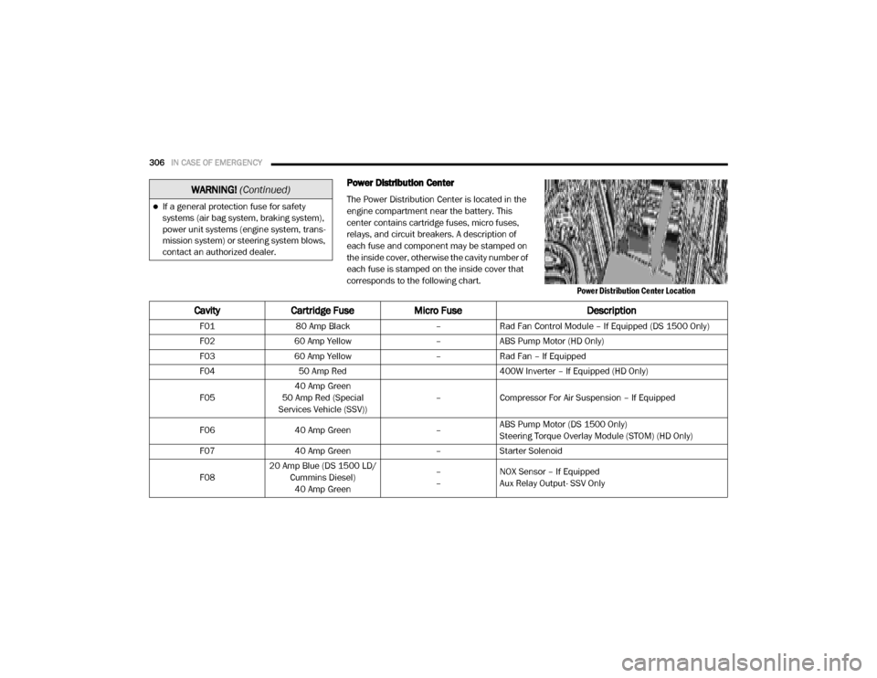
Power Distribution Center
The Power Distribution Center is located in the
engine compartment near the battery. This
center contains cartridge fuses, micro fuses,
relays, and circuit breakers. A description of
each fuse and component may be stamped on
the inside cover, otherwise the cavity number of
each fuse is stamped on the inside cover that
corresponds to the following chart.
Power Distribution Center Location
If a general protection fuse for safety
systems (air bag system, braking system),
power unit systems (engine system, trans-
mission system) or steering system blows,
contact an authorized dealer.
WARNING! (Continued)
Cavity Cartridge Fuse Micro Fuse Description
F0180 Amp Black –Rad Fan Control Module – If Equipped (DS 1500 Only)
F02 60 Amp Yellow –ABS Pump Motor (HD Only)
F03 60 Amp Yellow –Rad Fan – If Equipped
F04 50 Amp Red 400W Inverter – If Equipped (HD Only)
F05 40 Amp Green
50 Amp Red (Special
Services Vehicle (SSV)) –
Compressor For Air Suspension – If Equipped
F06 40 Amp Green –ABS Pump Motor (DS 1500 Only)
Steering Torque Overlay Module (STOM) (HD Only)
F07 40 Amp Green –Starter Solenoid
F08 20 Amp Blue (DS 1500 LD/
Cummins Diesel)40 Amp Green –
–
NOX Sensor – If Equipped
Aux Relay Output- SSV Only
2020_RAM_CHASSIS_CAB_OM_USA=GUID-6C67832B-7839-4CCF-BEFC-CDF988F949EA=1=en=.book Page 306
Page 311 of 516
IN CASE OF EMERGENCY309
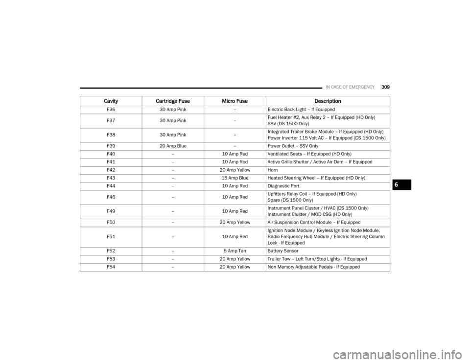
F3630 Amp Pink –Electric Back Light – If Equipped
F37 30 Amp Pink –Fuel Heater #2, Aux Relay 2 – If Equipped (HD Only)
SSV (DS 1500 Only)
F38 30 Amp Pink –Integrated Trailer Brake Module – If Equipped (HD Only)
Power Inverter 115 Volt AC – If Equipped (DS 1500 Only)
F39 20 Amp Blue –Power Outlet – SSV Only
F40 –10 Amp Red Ventilated Seats – If Equipped (HD Only)
F41 –10 Amp Red Active Grille Shutter / Active Air Dam – If Equipped
F42 –20 Amp Yellow Horn
F43 –15 Amp Blue Heated Steering Wheel – If Equipped (HD Only)
F44 –10 Amp Red Diagnostic Port
F46 –10 Amp RedUpfitters Relay Coil – If Equipped (HD Only)
Spare (DS 1500 Only)
F49 –10 Amp RedInstrument Panel Cluster / HVAC (DS 1500 Only)
Instrument Cluster / MOD CSG (HD Only)
F50 –20 Amp Yellow Air Suspension Control Module – If Equipped
F51 –10 Amp RedIgnition Node Module / Keyless Ignition Node Module,
Radio Frequency Hub Module / Electric Steering Column
Lock - If Equipped
F52 –5 Amp Tan Battery Sensor
F53 –20 Amp Yellow Trailer Tow – Left Turn/Stop Lights - If Equipped
F54 –20 Amp Yellow Non Memory Adjustable Pedals - If Equipped
CavityCartridge Fuse Micro Fuse Description
6
2020_RAM_CHASSIS_CAB_OM_USA=GUID-6C67832B-7839-4CCF-BEFC-CDF988F949EA=1=en=.book Page 309
Page 312 of 516
310IN CASE OF EMERGENCY
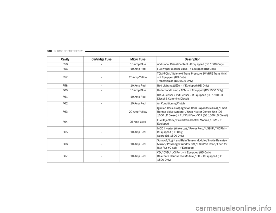
F56 –15 Amp Blue Additional Diesel Content - If Equipped (DS 1500 Only)
F56 –10 Amp Red Fuel Vapor Blocker Valve - If Equipped (HD Only)
F57 –20 Amp Yellow TCM/PCM / Solenoid Trans Pressure SW (RFE Trans Only)
– If Equipped (HD Only)
Transmission (DS 1500 Only)
F58 –10 Amp Red Bed Lighting (LED) – If Equipped (HD Only)
F60 –15 Amp Blue Underhood Lamp / TCM – If Equipped (DS 1500 Only)
F61 –10 Amp RedUREA Sensor / PM Sensor – If Equipped (DS 1500 LD
Diesel & Cummins Diesel)
F62 –10 Amp Red Air Conditioning Clutch
F63 –20 Amp Yellow Ignition Coils (Gas), Ignition Coils Capacitors (Gas) / Short
Runner Valve Actuator / Urea Heater Control Unit (DS
1500 LD Diesel) / RLY Coil Feed-SCR (DS 1500 LD Diesel)
F64 –25 Amp ClearFuel Injectors / Powertrain Control Module / SRV – If
Equipped
F65 –10 Amp RedMOD Inverter (Wake Up) / Power Port / USB IP / WCPM –
If Equipped (HD Only)
Spare (DS 1500 Only)
F66 –10 Amp RedSunroof / Light and Rain Sensor Module / Inside Rearview
Mirror / Passenger Window SW / USB Port Rear / Feed for
R/A RLY #2 Coil – If Equipped
F67 –10 Amp RedCD / DVD / UCI Port – If Equipped (HD Only)
Bluetooth Hands-Free Module / CD – If Equipped (DS
1500 Only)
Cavity
Cartridge Fuse Micro Fuse Description
2020_RAM_CHASSIS_CAB_OM_USA=GUID-6C67832B-7839-4CCF-BEFC-CDF988F949EA=1=en=.book Page 310
Page 314 of 516
312IN CASE OF EMERGENCY
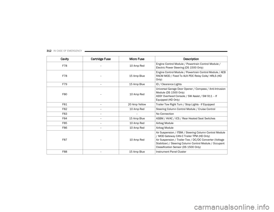
F78 –10 Amp RedEngine Control Module / Powertrain Control Module /
Electric Power Steering (DS 1500 Only)
F78 –15 Amp BlueEngine Control Module / Powertrain Control Module / AEB
RACM MOD / Feed To AUX PDC Relay Coils/ HRLS (HD
Only)
F79 –15 Amp Blue ID / Clearance Lights
F80 –10 Amp RedUniversal Garage Door Opener / Compass / Anti-Intrusion
Module (DS 1500 Only)
ASSY Overhead Console / SW Assist / SW 911 – If
Equipped (HD Only)
F81 –20 Amp Yellow Trailer Tow Right Turn / Stop Lights - If Equipped
F82 –10 Amp Red Steering Column Control Module / Cruise Control
F83 ––No Connection
F84 –15 Amp Blue ASBM / HVAC / ICS / Rear Heated Seat Switches
F85 –10 Amp Red Airbag Module
F86 –10 Amp Red Airbag Module
F87 –10 Amp RedAir Suspension / ITBM / Steering Column Control Module
/ MOD Gateway CAN-C Trailer TPM (HD Only)
Air Suspension / Trailer Tow / DC/DC Converter (Voltage
Stabilizer) / Steering Column Control Module / Occupant
Classification Sensor (DS 1500 Only)
F88 –15 Amp Blue Instrument Panel Cluster
CavityCartridge Fuse Micro Fuse Description
2020_RAM_CHASSIS_CAB_OM_USA=GUID-6C67832B-7839-4CCF-BEFC-CDF988F949EA=1=en=.book Page 312
Page 315 of 516
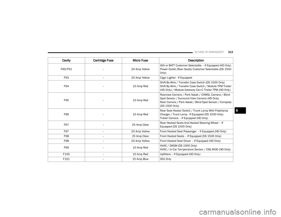
IN CASE OF EMERGENCY313
F90/F91 –20 Amp Yellow IGN or BATT Customer Selectable – If Equipped (HD Only)
Power Outlet (Rear Seats) Customer Selectable (DS 1500
Only)
F93 –20 Amp Yellow Cigar Lighter - If Equipped
F94 –10 Amp RedShift-By-Wire / Transfer Case Switch (DS 1500 Only)
Shift-By-Wire / Transfer Case Switch / Module TPM Trailer
(HD Only) / Module Gateway Can-C Trailer TPM (HD Only)
F95 –10 Amp RedRearview Camera / Park Assist / CHMSL Camera / Blind
Spot Sensor / Surround View Camera (HD Only)
Rear Camera / Park Assist / Blind Spot Sensor / Compass
(DS 1500 Only)
F96 –10 Amp RedRear Seat Heater Switch / Trunk Lamp With Flashlamp
Charger / Truck Lamp - If Equipped (DS 1500 Only)
Trailer Camera – If Equipped (HD Only)
F97 –25 Amp ClearRear Heated Seats And Heated Steering Wheel – If
Equipped (DS 1500 Only)
F97 –20 Amp Yellow Front Heated Seat Passenger – If Equipped (HD Only)
F98 –25 Amp Clear Front Heated Seats – If Equipped (DS 1500 Only)
F98 –20 Amp Yellow Front Heated Seat Driver – If Equipped (HD Only)
F99 –10 Amp RedHVAC / DASM (DS 1500 Only)
HVAC / In-Car Temperature Sensor / CSG MOD (HD Only)
F100 –10 Amp Red Upfitters – If Equipped (HD Only)
F101 –15 Amp Blue SSV Only
CavityCartridge Fuse Micro Fuse Description
6
2020_RAM_CHASSIS_CAB_OM_USA=GUID-6C67832B-7839-4CCF-BEFC-CDF988F949EA=1=en=.book Page 313
Page 357 of 516

SERVICING AND MAINTENANCE355
If water is detected in the water separator while
the engine is running, or while the ignition
switch is in the ON position, the “Water In Fuel
Indicator Light” will illuminate and an audible
chime will be heard five times. At this point you
should stop the engine and drain the water from
both of the filters.
If the “Water In Fuel Indicator Light” comes on
and a single chime is heard while you are
driving, or with the ignition switch in the ON
position, there may be a problem with your
water separator wiring or sensor. See an autho -
rized dealer for service. Upon proper draining of the water from both
fuel filters, the “Water In Fuel Indicator Light”
will remain illuminated for approximately 10
seconds. If the water was drained while the
engine was running, the “Water In Fuel Indicator
Light” may remain on for approximately three
minutes.
NOTE:
Care should be taken in disposing of used fluids
from your vehicle. Used fluids, indiscriminately
discarded, can present a problem to the envi
-
ronment. Contact an authorized dealer, service
station, or government agency for advice on
recycling programs and for where used fluids
and filters can be properly disposed of in your
area.
Drain the fuel/water separator filters when the
“Water In Fuel Indicator Light” is ON. Within
10 minutes of vehicle shutdown, turn the
engine mounted filter drain valve (located on
the side of the filter assembly) counterclock -
wise quarter turn, and turn the under body
mounted filter drain valve (located on the
bottom of the filter assembly) counterclockwise
wise 1 full turn. Then turn the ignition switch to the ON position, and allow any accumulated
water to drain. Leave the drain valve open until
all water and contaminants have been
removed. When clean fuel is visible, close the
drain valve following these guidelines:
1. Rotate the drain clockwise to close until
you feel resistance from the internal seal.
2. Continue turning the drain half of a turn to properly compress the seal.
NOTE:
Over-compression of the seal due to over-tight -
ening of the drain will damage the seal, cause a
leak, and require the entire sensor to be
replaced.
3. Turn the ignition switch to OFF.
The sensor drain should not be over-tightened
during normal service operations to avoid
internal damage and future fuel leaks. The
drain should be closed and secured without the
use of tools.
If more than a couple ounces/milliliters of fuel
have been drained, follow the directions for
“Priming If The Engine Has Run Out Of Fuel.”
CAUTION!
Do not drain the fuel/water separator filter
when the engine is running.
Diesel fuel will damage blacktop paving
surfaces. Drain the filter into an appro-
priate container.
CAUTION!
If the “Water In Fuel Indicator Light” remains
on, DO NOT START the engine before you
drain water from the fuel filters to avoid
engine damage.
7
2020_RAM_CHASSIS_CAB_OM_USA=GUID-6C67832B-7839-4CCF-BEFC-CDF988F949EA=1=en=.book Page 355
Page 359 of 516

SERVICING AND MAINTENANCE357
Underbody Mounted Fuel Filter
Replacement
NOTE:
Using a fuel filter that does not meet the
manufacturer's filtration and water sepa -
rating requirements can severely impact fuel
system life and reliability.
The underbody mounted filter housing will
cause the engine not to run if:
a. No filter is installed.
Underbody Mounted Fuel Filter Assembly
1. Ensure engine is turned off.
2. Place drain pan under the fuel filter drain
hose.
3. Open the water drain valve one full turn counterclockwise and completely drain fuel
and water into the approved container.
4. Close the water drain valve. 5. Remove lid using a socket or strap wrench.
Rotate counterclockwise for removal.
Remove used o-ring and discard it.
6. Remove the used filter cartridge from the housing and dispose of according to your
local regulations.
7. Wipe clean the sealing surfaces of the lid and housing.
8. Install new o-ring back into ring groove on the filter housing and lubricate with clean
engine oil.
NOTE:
Water In Fuel (WIF) sensor is re-usable. Service
kit comes with new o-ring for filter canister and
WIF sensor.
1 — Drain Valve
CAUTION!
Diesel fuel will damage blacktop paving
surfaces. Drain the filter into an appro-
priate container.
Do not prefill the fuel filter when installing a
new fuel filter. There is a possibility debris
could be introduced into the fuel filter
during this action. It is best to install the
filter dry and allow the in-tank lift pump to
prime the fuel system.
7
2020_RAM_CHASSIS_CAB_OM_USA=GUID-6C67832B-7839-4CCF-BEFC-CDF988F949EA=1=en=.book Page 357
Page 386 of 516

384SERVICING AND MAINTENANCE
Radial Ply Tires
Tire Repair
If your tire becomes damaged, it may be
repaired if it meets the following criteria:
The tire has not been driven on when flat.
The damage is only on the tread section of
your tire (sidewall damage is not repairable).
The puncture is no greater than a ¼ of an
inch (6 mm).
Consult an authorized tire dealer for tire repairs
and additional information. Damaged Run Flat tires, or Run Flat tires that
have experienced a loss of pressure should be
replaced immediately with another Run Flat tire
of identical size and service description (Load
Index and Speed Symbol). Replace the tire pres
-
sure sensor as well as it is not designed to be
reused.
Run Flat Tires — If Equipped
Run Flat tires allow you the capability to drive
50 miles (80 km) at 50 mph (80 km/h) after a
rapid loss of inflation pressure. This rapid loss
of inflation is referred to as the Run Flat mode.
A Run Flat mode occurs when the tire inflation
pressure is of/or below 14 psi (96 kPa). Once a
Run Flat tire reaches the run flat mode it has
limited driving capabilities and needs to be
replaced immediately. A Run Flat tire is not
repairable. When a run flat tire is changed after
driving with underinflated tire condition, please
replace the TPM sensor as it is not designed to
be reused when driven under run flat mode
14 psi (96 kPa) condition. NOTE:
TPM Sensor must be replaced after driving the
vehicle on a flat tire condition.
It is not recommended driving a vehicle loaded
at full capacity or to tow a trailer while a tire is in
the run flat mode.
See the tire pressure monitoring section for
more information.Tire Spinning
When stuck in mud, sand, snow, or ice condi
-
tions, do not spin your vehicle's wheels above
30 mph (48 km/h) or for longer than 30
seconds continuously without stopping.
Refer to “Freeing A Stuck Vehicle” in “In Case Of
Emergency” for further information.
WARNING!
Combining radial ply tires with other types of
tires on your vehicle will cause your vehicle to
handle poorly. The instability could cause a
collision. Always use radial ply tires in sets of
four. Never combine them with other types of
tires.
WARNING!
Fast spinning tires can be dangerous. Forces
generated by excessive wheel speeds may
cause tire damage or failure. A tire could
explode and injure someone. Do not spin your
vehicle's wheels faster than 30 mph
(48 km/h) for more than 30 seconds
continuously when you are stuck, and do not
let anyone near a spinning wheel, no matter
what the speed.
2020_RAM_CHASSIS_CAB_OM_USA=GUID-6C67832B-7839-4CCF-BEFC-CDF988F949EA=1=en=.book Page 384
Page 393 of 516

SERVICING AND MAINTENANCE391
Tire Rotation Recommendations
Tires on the front and rear axles of vehicles
operate at different loads and perform different
steering, driving, and braking functions. For
these reasons, they wear at unequal rates.
These effects can be reduced by timely rotation
of tires. The benefits of rotation are especially
worthwhile with aggressive tread designs such
as those on On/Off Road type tires. Rotation will
increase tread life, help to maintain mud, snow,
and wet traction levels, and contribute to a
smooth, quiet ride. Refer to the “Maintenance Plan” for the proper
maintenance intervals. More frequent rotation
is permissible if desired. The reasons for any
rapid or unusual wear should be corrected prior
to rotation being performed.
Tire Rotation
NOTE:
On Canadian vehicles only, if your vehicle is
equipped with All-Season type tires on the front
and On/Off Road type tires mounted on the
rear, do not use a front to back rotation pattern.
Instead, rotate your tires side to side at the
recommended intervals.
Dual Rear Wheels
Tire Rotation
The tires used on dual wheel assemblies should
be matched for wear to prevent overloading one
tire in a set. To check if tires are even, lay a
straight edge across all four tires. The straight
edge should touch all the tires.
NOTE:
If your vehicle is equipped with a Tire Pressure
Information System (TPIS):
The Tire Pressure Information System (TPIS)
uses unique sensors in the inner rear wheels
to help identify them from the outer rear
wheels, because of this, the inner and outer
wheel locations can’t be switched.
Observe the traction device manufacturer’s
instructions on the method of installation,
operating speed, and conditions for use.
Always use the suggested operating speed
of the device manufacturer’s if it is less
than 30 mph (48 km/h).
Do not use traction devices on a compact
spare tire.
CAUTION! (Continued)
7
2020_RAM_CHASSIS_CAB_OM_USA=GUID-6C67832B-7839-4CCF-BEFC-CDF988F949EA=1=en=.book Page 391
Page 394 of 516

392SERVICING AND MAINTENANCE
(Continued)
After a tire rotation is completed, as shown
below, the system can auto learn the loca -
tions of each sensor ID. Auto learning/local -
ization occurs when the vehicle ignition
status is changed from Off to On and speeds
of greater than 5 mph (8 km/h) are obtained and remain over 5 mph (8 km/h) for at about
a 15 minute period. You may need to drive
for 20 minutes to account slower speeds and
stops.
If the tires are rotated incorrectly, the Auto
localization of the TPIS sensors will fail to
locate correctly resulting in incorrect loca -
tions for the pressure values displayed in the
Instrument Cluster.
DEPARTMENT OF TRANSPORTATION
UNIFORM TIRE QUALITY GRADES
The following tire grading categories
were established by the National
Highway Traffic Safety Administration.
The specific grade rating assigned by the
tire's manufacturer in each category is
shown on the sidewall of the tires on
your vehicle.
All passenger vehicle tires must conform
to Federal safety requirements in addi -
tion to these grades.
Treadwear
The Treadwear grade is a comparative
rating, based on the wear rate of the tire
when tested under controlled conditions
on a specified government test course.
For example, a tire graded 150 would
wear one and one-half times as well on
the government course as a tire graded
100. The relative performance of tires
depends upon the actual conditions of
their use, however, and may depart
significantly from the norm due to varia -
tions in driving habits, service practices,
and differences in road characteristics
and climate.
Traction Grades
The Traction grades, from highest to
lowest, are AA, A, B, and C. These grades
represent the tire's ability to stop on wet
pavement, as measured under
controlled conditions on specified
government test surfaces of asphalt and
concrete. A tire marked C may have poor
traction performance.
CAUTION!
4500/5500 Dual Rear Tires may only have
one approved direction of rotation. This is
to accommodate the asymmetrical design
(tread pattern) of the On/Off road tire.
When replacing a flat, the spare tire may
have to be remounted on the rim or
installed at a different location to maintain
the correct placement of the tire on the
wheel relative to the tire/wheel position on
the vehicle. For example, if the spare is
used to replace an outer rear tire it will have
to be remounted on the rim so that the
wheel is dished inward. That way the tread
design of asymmetrical tires will maintain
proper position.
CAUTION! (Continued)
2020_RAM_CHASSIS_CAB_OM_USA=GUID-6C67832B-7839-4CCF-BEFC-CDF988F949EA=1=en=.book Page 392