Brake check Ram 4500 Chassis Cab 2020 Owner's Manual
[x] Cancel search | Manufacturer: RAM, Model Year: 2020, Model line: 4500 Chassis Cab, Model: Ram 4500 Chassis Cab 2020Pages: 516, PDF Size: 29.24 MB
Page 6 of 516
4
ONBOARD DIAGNOSTIC SYSTEM — OBD II ....... 118
Onboard Diagnostic System (OBD II)
Cybersecurity..............................................118
EMISSIONS INSPECTION AND MAINTENANCE
PROGRAMS ...................................................... 119
SAFETY
SAFETY FEATURES ............................................ 120
Anti-Lock Brake System (ABS) ................. 120
Electronic Brake Control (EBC) System ...121
AUXILIARY DRIVING SYSTEMS ........................ 129
Forward Collision Warning (FCW) With
Mitigation — If Equipped............................129 Tire Pressure Monitoring System
(TPMS) .....................................................132
OCCUPANT RESTRAINT SYSTEMS .................. 141
Occupant Restraint Systems Features ....141
Important Safety Precautions ...................141Seat Belt Systems ..................................... 142Supplemental Restraint Systems (SRS) ...151Child Restraints ........................................160
Transporting Pets ....................................179
SAFETY TIPS .................................................... 180
Transporting Passengers ..........................180
Exhaust Gas ........................................... 180
Safety Checks You Should Make Inside
The Vehicle ................................................180 Periodic Safety Checks You Should Make
Outside The Vehicle ...................................182
STARTING AND OPERATING
STARTING THE ENGINE — GAS ENGINE .........183
Automatic Transmission............................ 183
Tip Start Feature ....................................... 183Keyless Enter-N-Go — Ignition ................... 184
Normal Starting Using ENGINE START/
STOP Button ............................................ 184 Cold Weather Operation
(Below –22°F Or −30°C) ......................... 187 After Starting .............................................. 187
STARTING THE ENGINE — DIESEL ENGINE .... 187
Automatic Transmission............................ 187
Keyless Enter-N-Go — Ignition ................... 188
Extreme Cold Weather .............................. 190
Normal Starting Procedure — Engine Manifold
Air Temperature Above 66°F (19°C) ....... 191 Starting Procedure — Engine Manifold Air
Temperature 0°F To 66°F
(–18°C to 19°C) ....................................... 191 Starting Procedure — Engine Manifold Air
Temperature Below 0°F (-18°C) .............. 192 Starting Fluids ............................................ 193 NORMAL OPERATION — DIESEL ENGINE ....... 194
Cold Weather Precautions ........................ 194
Engine Idling ............................................. 197
Noise .......................................................... 198
Stopping The Engine ................................. 198Idle Shutdown ............................................ 199
Programmable Maximum Vehicle Speed ..... 199
Operating Precautions .............................. 200
Cooling System Tips .................................. 200
Diesel Particulate Filter (DPF) Manual
Regeneration - If Equipped ....................... 201
ENGINE BLOCK HEATER — IF EQUIPPED ........ 201
ENGINE BREAK-IN RECOMMENDATIONS —
GAS ENGINE ...................................................... 202
ENGINE BREAK-IN RECOMMENDATIONS —
DIESEL ENGINE .................................................. 202
DIESEL EXHAUST BRAKE
(ENGINE BRAKING) ........................................... 203
PARKING BRAKE .............................................. 204
AUTOMATIC TRANSMISSION ........................... 205 Ignition Park Interlock ............................... 206Brake/Transmission Shift Interlock
System ....................................................... 206 Six–Speed Automatic Transmission —
If Equipped ................................................ 207 Eight-Speed Automatic Transmission —
If Equipped ................................................. 213
AUXILIARY SWITCHES — IF EQUIPPED ........... 218
2020_RAM_CHASSIS_CAB_OM_USA=GUID-6C67832B-7839-4CCF-BEFC-CDF988F949EA=1=en=.book Page 4
Page 9 of 516
7
SERVICING AND MAINTENANCE
SCHEDULED SERVICING — GAS ENGINE ....... 329Maintenance Plan......................................330
Heavy Duty Use Of The Vehicle ................. 333
SCHEDULED SERVICING — DIESEL ENGINE .. 334
Oil Change Indicator System —
Cummins Diesel .........................................335 Perform Service Indicator —
Cummins Diesel ........................................335 Maintenance Plan — Cummins
Diesel Engine ............................................336
ENGINE COMPARTMENT ................................ 343
6.4L Engine ...............................................3436.7L Engine ................................................344
Checking Oil Level — Gas Engine .............345
Checking Oil Level — Diesel Engine ..........345
Adding Washer Fluid ................................345Maintenance-Free Battery .......................346
Pressure Washing ......................................346
DEALER SERVICE .............................................. 347
Engine Oil .................................................. 347Engine Oil Filter ........................................349
Engine Air Cleaner Filter .........................349
Air Conditioner Maintenance ................. 351
Accessory Drive Belt Inspection................354Draining Fuel/Water Separator Filter .....354
Engine Mounted Fuel Filter
Replacement ..............................................356 Underbody Mounted Fuel Filter
Replacement ..............................................357 Priming If The Engine Has Run
Out Of Fuel ................................................ 358 Intervention Regeneration Strategy —
Message Process Flow ............................. 359 Diesel Exhaust Fluid .................................. 359Body Lubrication ...................................... 360
Windshield Wiper Blades ........................ 360
Exhaust System ........................................ 362
Cooling System ......................................... 363
Charge Air Cooler — Inter-Cooler .............. 366
Brake System ............................................ 367Automatic Transmission............................ 368
Rear Axle And 4x4 Front Driving Axle Fluid
Level ....................................................... 370 Transfer Case ............................................ 371Noise Control System Required
Maintenance & Warranty ......................... 371
HOISTING ............................................................374
TIRES....................................................................374
Tire Safety Information ........................... 374
Tires — General Information .................... 382
Tire Types ................................................... 386
Spare Tires — If Equipped ....................... 387
Wheel And Wheel Trim Care .................. 389Tire Chains and Traction Devices ............ 390
Tire Rotation Recommendations .............. 391 DEPARTMENT OF TRANSPORTATION UNIFORM
TIRE QUALITY GRADES .................................... 392
Treadwear .................................................. 392
Traction Grades ......................................... 392Temperature Grades ................................. 393
STORING THE VEHICLE .................................. 393
BODYWORK ........................................................ 393 Protection From Atmospheric Agents ..... 393
Body And Underbody Maintenance .......... 394Preserving The Bodywork.......................... 394
INTERIORS ......................................................... 395
Seats And Fabric Parts .............................. 395
Plastic And Coated Parts........................... 396
Leather Parts ............................................. 396
Glass Surfaces .......................................... 396
TECHNICAL SPECIFICATIONS
IDENTIFICATION DATA ...................................... 397Vehicle Identification Number ................. 397
BRAKE SYSTEM ................................................ 397
Hydraulic Brake Assist — If Equipped....... 397
WHEEL AND TIRE TORQUE
SPECIFICATIONS .............................................. 397
Torque Specifications .............................. 398
2020_RAM_CHASSIS_CAB_OM_USA=GUID-6C67832B-7839-4CCF-BEFC-CDF988F949EA=1=en=.book Page 7
Page 111 of 516

GETTING TO KNOW YOUR INSTRUMENT PANEL109
Brake Warning Light
This warning light monitors various
brake functions, including brake
fluid level and parking brake appli-
cation. If the brake light turns on it
may indicate that the parking brake is
applied, that the brake fluid level is low, or
that there is a problem with the anti-lock
brake system reservoir.
If the light remains on when the parking brake
has been disengaged, and the fluid level is at
the full mark on the master cylinder reservoir, it
indicates a possible brake hydraulic system
malfunction or that a problem with the Brake
Booster has been detected by the Anti-Lock
Brake System (ABS) / Electronic Stability
Control (ESC) system. In this case, the light will
remain on until the condition has been
corrected. If the problem is related to the brake
booster, the ABS pump will run when applying
the brake, and a brake pedal pulsation may be
felt during each stop.
The dual brake system provides a reserve
braking capacity in the event of a failure to a
portion of the hydraulic system. A leak in either
half of the dual brake system is indicated by the
Brake Warning Light, which will turn on when the brake fluid level in the master cylinder has
dropped below a specified level.
The light will remain on until the cause is
corrected.
NOTE:
The light may flash momentarily during sharp
cornering maneuvers, which change fluid level
conditions. The vehicle should have service
performed, and the brake fluid level checked.
If brake failure is indicated, immediate repair is
necessary.
Vehicles equipped with the Anti-Lock Brake
System (ABS) are also equipped with Electronic
Brake Force Distribution (EBD). In the event of
an EBD failure, the Brake Warning Light will turn
on along with the ABS Light. Immediate repair to
the ABS system is required.
Operation of the Brake Warning Light can be
checked by turning the ignition switch from the
OFF position to the ON/RUN position. The light
should illuminate for approximately two
seconds. The light should then turn off unless
the parking brake is applied or a brake fault is
detected. If the light does not illuminate, have
the light inspected by an authorized dealer.
The light also will turn on when the parking
brake is applied with the ignition switch in the
ON/RUN position.
NOTE:
This light shows only that the parking brake is
applied. It does not show the degree of brake
application.
Hood Open Warning Light
This warning light will illuminate when
the hood is ajar/open and not fully
closed.
NOTE:
If the vehicle is moving, there will also be a
single chime.
WARNING!
Driving a vehicle with the red brake light on is
dangerous. Part of the brake system may
have failed. It will take longer to stop the
vehicle. You could have a collision. Have the
vehicle checked immediately.
3
2020_RAM_CHASSIS_CAB_OM_USA=GUID-6C67832B-7839-4CCF-BEFC-CDF988F949EA=1=en=.book Page 109
Page 112 of 516
110GETTING TO KNOW YOUR INSTRUMENT PANEL
Vehicle Security Warning Light — If Equipped
This light will flash at a fast rate for
approximately 15 seconds when the
vehicle security alarm is arming, and
then will flash slowly until the vehicle
is disarmed.
Engine Coolant Temperature Warning Light
This warning light warns of an over -
heated engine condition. If the engine
coolant temperature is too high, this
indicator will illuminate and a single
chime will sound. If the temperature reaches
the upper limit, a continuous chime will sound
for four minutes or until the engine is able to
cool, whichever comes first.
If the light turns on while driving, safely pull over
and stop the vehicle. If the A/C system is on,
turn it off. Also, shift the transmission into
NEUTRAL and idle the vehicle. If the tempera -
ture reading does not return to normal, turn the
engine off immediately and call for service.
Refer to “If Your Engine Overheats” in “In Case
Of Emergency” for further information.
Battery Charge Warning Light
This warning light will illuminate when
the battery is not charging properly. If
it stays on while the engine is running,
there may be a malfunction with the
charging system. Contact an authorized dealer
as soon as possible.
This indicates a possible problem with the elec -
trical system or a related component.
Oil Pressure Warning Light
This warning light will illuminate to
indicate low engine oil pressure. If the
light turns on while driving, stop the
vehicle, shut off the engine as soon as
possible, and contact an authorized dealer. A
chime will sound when this light turns on.
Do not operate the vehicle until the cause is
corrected. This light does not indicate how
much oil is in the engine. The engine oil level
must be checked under the hood.
Oil Temperature Warning Light
This warning light will illuminate to
indicate the engine oil temperature is
high. If the light turns on while driving,
stop the vehicle and shut off the
engine as soon as possible. Wait for oil
temperature to return to normal levels.
Electronic Throttle Control (ETC) Warning
Light
This warning light will illuminate to
indicate a problem with the Electronic
Throttle Control (ETC) system. If a
problem is detected while the vehicle
is running, the light will either stay on or flash
depending on the nature of the problem. Cycle
the ignition when the vehicle is safely and
completely stopped and the transmission is
placed in the PARK position. The light should
turn off. If the light remains on with the vehicle
running, your vehicle will usually be drivable;
however, see an authorized dealer for service
as soon as possible.
NOTE:
This light may turn on if the accelerator and
brake pedals are pressed at the same time.
2020_RAM_CHASSIS_CAB_OM_USA=GUID-6C67832B-7839-4CCF-BEFC-CDF988F949EA=1=en=.book Page 110
Page 113 of 516
GETTING TO KNOW YOUR INSTRUMENT PANEL111
If the light continues to flash when the vehicle is
running, immediate service is required and you
may experience reduced performance, an
elevated/rough idle, or engine stall and your
vehicle may require towing. The light will come
on when the ignition is placed in the ON/RUN or
ACC/ON/RUN position and remain on briefly as
a bulb check. If the light does not come on
during starting, have the system checked by an
authorized dealer.
Electric Power Steering Fault Warning Light
This warning light will turn on when
there's a fault with the Electric Power
Steering (EPS) system. Refer to
“Power Steering” in “Starting And
Operating” for further information.
Trailer Brake Disconnected Warning Light
This warning light will illuminate when
the Trailer Brake has been discon -
nected.
Refer to “Trailer Towing” in “Starting And Oper -
ating” for further information.
Transmission Temperature Warning Light — If
Equipped
This warning light will illuminate to
warn of a high transmission fluid
temperature. This may occur with
strenuous usage such as trailer
towing. If this light turns on, stop the vehicle and
run the engine at idle or slightly faster, with the
transmission in PARK or NEUTRAL, until the
light turns off. Once the light turns off, you may
continue to drive normally.
Door Open Warning Light
This indicator will illuminate when a
door is ajar/open and not fully closed.
NOTE:
If the vehicle is moving there will also be a single
chime.
Yellow Warning Lights
Adaptive Cruise Control (ACC) Fault Warning
Light — If Equipped
This warning light will illuminate to
indicate a fault in the ACC system.
Contact a local authorized dealer for
service.
For further information, refer to “Adaptive
Cruise Control (ACC)” in “Starting And Oper -
ating.”
WARNING!
Continued operation with reduced assist
could pose a safety risk to yourself and
others. Service should be obtained as soon
as possible.WARNING!
If you continue operating the vehicle when
the Transmission Temperature Warning Light
is illuminated you could cause the fluid to boil
over, come in contact with hot engine or
exhaust components and cause a fire.
CAUTION!
Continuous driving with the Transmission
Temperature Warning Light illuminated will
eventually cause severe transmission
damage or transmission failure.
3
2020_RAM_CHASSIS_CAB_OM_USA=GUID-6C67832B-7839-4CCF-BEFC-CDF988F949EA=1=en=.book Page 111
Page 116 of 516
114GETTING TO KNOW YOUR INSTRUMENT PANEL
Your vehicle has also been equipped with a
TPMS malfunction indicator to indicate when
the system is not operating properly. The TPMS
malfunction indicator is combined with the low
tire pressure telltale. When the system detects
a malfunction, the telltale will flash for approxi-
mately one minute and then remain continu -
ously illuminated. This sequence will continue
upon subsequent vehicle start-ups as long as
the malfunction exists. When the malfunction
indicator is illuminated, the system may not be
able to detect or signal low tire pressure as
intended. TPMS malfunctions may occur for a
variety of reasons, including the installation of
replacement or alternate tires or wheels on the
vehicle that prevent the TPMS from functioning
properly. Always check the TPMS malfunction
telltale after replacing one or more tires or
wheels on your vehicle to ensure that the
replacement or alternate tires and wheels allow
the TPMS to continue to function properly.
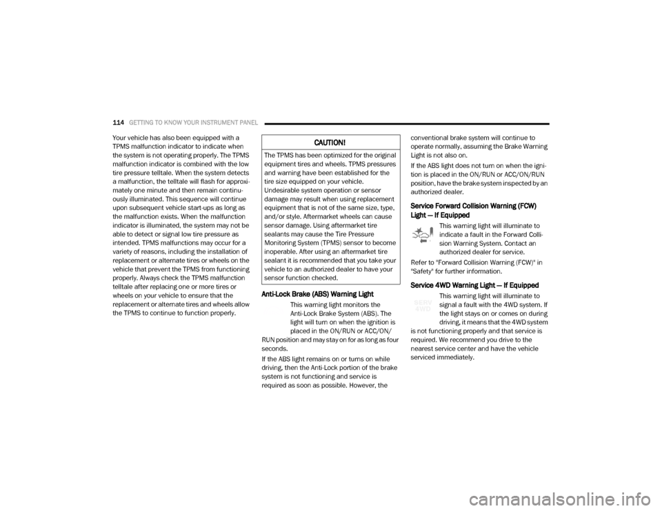
Anti-Lock Brake (ABS) Warning Light
This warning light monitors the
Anti-Lock Brake System (ABS). The
light will turn on when the ignition is
placed in the ON/RUN or ACC/ON/
RUN position and may stay on for as long as four
seconds.
If the ABS light remains on or turns on while
driving, then the Anti-Lock portion of the brake
system is not functioning and service is
required as soon as possible. However, the conventional brake system will continue to
operate normally, assuming the Brake Warning
Light is not also on.
If the ABS light does not turn on when the igni
-
tion is placed in the ON/RUN or ACC/ON/RUN
position, have the brake system inspected by an
authorized dealer.
Service Forward Collision Warning (FCW)
Light — If Equipped
This warning light will illuminate to
indicate a fault in the Forward Colli -
sion Warning System. Contact an
authorized dealer for service.
Refer to "Forward Collision Warning (FCW)" in
"Safety" for further information.
Service 4WD Warning Light — If Equipped
This warning light will illuminate to
signal a fault with the 4WD system. If
the light stays on or comes on during
driving, it means that the 4WD system
is not functioning properly and that service is
required. We recommend you drive to the
nearest service center and have the vehicle
serviced immediately.
CAUTION!
The TPMS has been optimized for the original
equipment tires and wheels. TPMS pressures
and warning have been established for the
tire size equipped on your vehicle.
Undesirable system operation or sensor
damage may result when using replacement
equipment that is not of the same size, type,
and/or style. Aftermarket wheels can cause
sensor damage. Using aftermarket tire
sealants may cause the Tire Pressure
Monitoring System (TPMS) sensor to become
inoperable. After using an aftermarket tire
sealant it is recommended that you take your
vehicle to an authorized dealer to have your
sensor function checked.
2020_RAM_CHASSIS_CAB_OM_USA=GUID-6C67832B-7839-4CCF-BEFC-CDF988F949EA=1=en=.book Page 114
Page 119 of 516
GETTING TO KNOW YOUR INSTRUMENT PANEL117
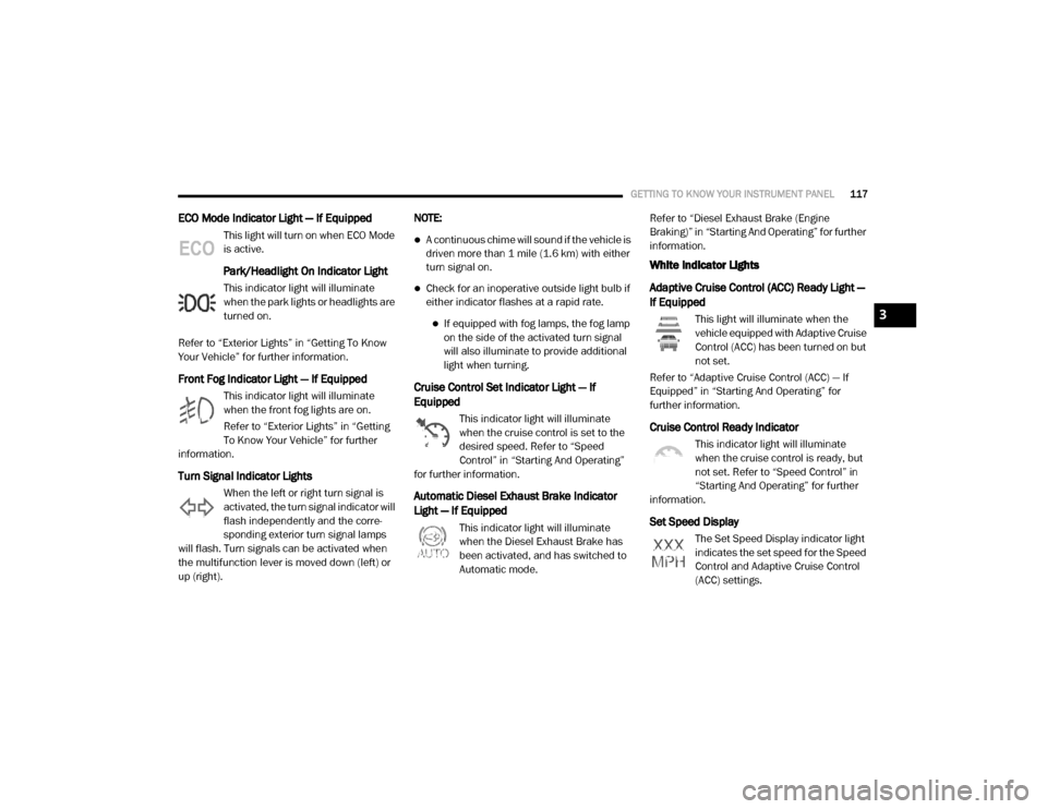
ECO Mode Indicator Light — If Equipped
This light will turn on when ECO Mode
is active.
Park/Headlight On Indicator Light
This indicator light will illuminate
when the park lights or headlights are
turned on.
Refer to “Exterior Lights” in “Getting To Know
Your Vehicle” for further information.
Front Fog Indicator Light — If Equipped
This indicator light will illuminate
when the front fog lights are on.
Refer to “Exterior Lights” in “Getting
To Know Your Vehicle” for further
information.
Turn Signal Indicator Lights
When the left or right turn signal is
activated, the turn signal indicator will
flash independently and the corre -
sponding exterior turn signal lamps
will flash. Turn signals can be activated when
the multifunction lever is moved down (left) or
up (right). NOTE:
A continuous chime will sound if the vehicle is
driven more than 1 mile (1.6 km) with either
turn signal on.
Check for an inoperative outside light bulb if
either indicator flashes at a rapid rate.
If equipped with fog lamps, the fog lamp
on the side of the activated turn signal
will also illuminate to provide additional
light when turning.
Cruise Control Set Indicator Light — If
Equipped
This indicator light will illuminate
when the cruise control is set to the
desired speed. Refer to “Speed
Control” in “Starting And Operating”
for further information.
Automatic Diesel Exhaust Brake Indicator
Light — If Equipped
This indicator light will illuminate
when the Diesel Exhaust Brake has
been activated, and has switched to
Automatic mode. Refer to “Diesel Exhaust Brake (Engine
Braking)” in “Starting And Operating” for further
information.
White Indicator Lights
Adaptive Cruise Control (ACC) Ready Light —
If Equipped
This light will illuminate when the
vehicle equipped with Adaptive Cruise
Control (ACC) has been turned on but
not set.
Refer to “Adaptive Cruise Control (ACC) — If
Equipped” in “Starting And Operating” for
further information.
Cruise Control Ready Indicator
This indicator light will illuminate
when the cruise control is ready, but
not set. Refer to “Speed Control” in
“Starting And Operating” for further
information.
Set Speed Display
The Set Speed Display indicator light
indicates the set speed for the Speed
Control and Adaptive Cruise Control
(ACC) settings.
3
2020_RAM_CHASSIS_CAB_OM_USA=GUID-6C67832B-7839-4CCF-BEFC-CDF988F949EA=1=en=.book Page 117
Page 122 of 516
120(Continued)
SAFETY
SAFETY FEATURES
Anti-Lock Brake System (ABS)
The Anti-Lock Brake System (ABS) provides
increased vehicle stability and brake perfor-
mance under most braking conditions. The
system automatically prevents wheel lock, and
enhances vehicle control during braking.
The ABS performs a self-check cycle to ensure
that the ABS is working properly each time the
vehicle is started and driven. During this
self-check, you may hear a slight clicking sound
as well as some related motor noises.
ABS is activated during braking when the
system detects one or more wheels begin to
lock. Road conditions such as ice, snow, gravel,
bumps, railroad tracks, loose debris, or panic
stops may increase the likelihood of ABS activa-
tion(s). You also may experience the following when
ABS activates:
The ABS motor noise (it may continue to run
for a short time after the stop)
The clicking sound of solenoid valves
Brake pedal pulsations
A slight drop of the brake pedal at the end of
the stop
These are all normal characteristics of ABS.
WARNING!
The ABS contains sophisticated electronic
equipment that may be susceptible to inter -
ference caused by improperly installed or
high output radio transmitting equipment.
This interference can cause possible loss of
anti-lock braking capability. Installation of
such equipment should be performed by
qualified professionals.
Pumping of the Anti-Lock Brakes will
diminish their effectiveness and may lead
to a collision. Pumping makes the stopping
distance longer. Just press firmly on your
brake pedal when you need to slow down or
stop.
The ABS cannot prevent the natural laws of
physics from acting on the vehicle, nor can
it increase braking or steering efficiency
beyond that afforded by the condition of the
vehicle brakes and tires or the traction
afforded.
The ABS cannot prevent collisions,
including those resulting from excessive
speed in turns, following another vehicle
too closely, or hydroplaning.
The capabilities of an ABS equipped vehicle
must never be exploited in a reckless or
dangerous manner that could jeopardize
the user’s safety or the safety of others.
WARNING! (Continued)
2020_RAM_CHASSIS_CAB_OM_USA=GUID-6C67832B-7839-4CCF-BEFC-CDF988F949EA=1=en=.book Page 120
Page 160 of 516

158SAFETY
(Continued)
Enhanced Accident Response System
In the event of an impact, if the communication
network remains intact, and the power remains
intact, depending on the nature of the event,
the ORC will determine whether to have the
Enhanced Accident Response System perform
the following functions:
Cut off fuel to the engine (If Equipped)
Cut off battery power to the electric motor (If
Equipped)
Flash hazard lights as long as the battery has
power
Turn on the interior lights, which remain on
as long as the battery has power or for
15 minutes from the intervention of the
Enhanced Accident Response System.
Unlock the power door locks.
Your vehicle may also be designed to perform
any of these other functions in response to the
Enhanced Accident Response System:
Turn off the Fuel Filter Heater, Turn off the
HVAC Blower Motor, Close the HVAC Circula -
tion Door
Cut off battery power to the:
Engine
Electric Motor (if equipped)
Electric power steering
Brake booster
Electric park brake
Automatic transmission gear selector
Horn
Front wiper
Headlamp washer pump
NOTE:
After an accident, remember to place the igni -
tion to the STOP (OFF/LOCK) position and
remove the key from the ignition switch to avoid
draining the battery. Carefully check the vehicle
for fuel leaks in the engine compartment and on
the ground near the engine compartment and
fuel tank before resetting the system and
starting the engine. If there are no fuel leaks or
damage to the vehicle electrical devices (e.g.
headlights) after an accident, reset the system
by following the procedure described below. If
you have any doubt, contact an authorized
dealer.
Enhanced Accident Response System Reset
Procedure
In order to reset the Enhanced Accident
Response System functions after an event, the
ignition switch must be changed from ignition
START or ON/RUN to ignition OFF. Carefully
check the vehicle for fuel leaks in the engine
compartment and on the ground near the
engine compartment and fuel tank before reset -
ting the system and starting the engine.
Maintaining Your Air Bag System
WARNING!
Modifications to any part of the air bag
system could cause it to fail when you need
it. You could be injured if the air bag system
is not there to protect you. Do not modify
the components or wiring, including adding
any kind of badges or stickers to the
steering wheel hub trim cover or the upper
passenger side of the instrument panel. Do
not modify the front bumper, vehicle body
structure, or add aftermarket side steps or
running boards.
2020_RAM_CHASSIS_CAB_OM_USA=GUID-6C67832B-7839-4CCF-BEFC-CDF988F949EA=1=en=.book Page 158
Page 183 of 516
SAFETY181
(Continued)
(Continued)
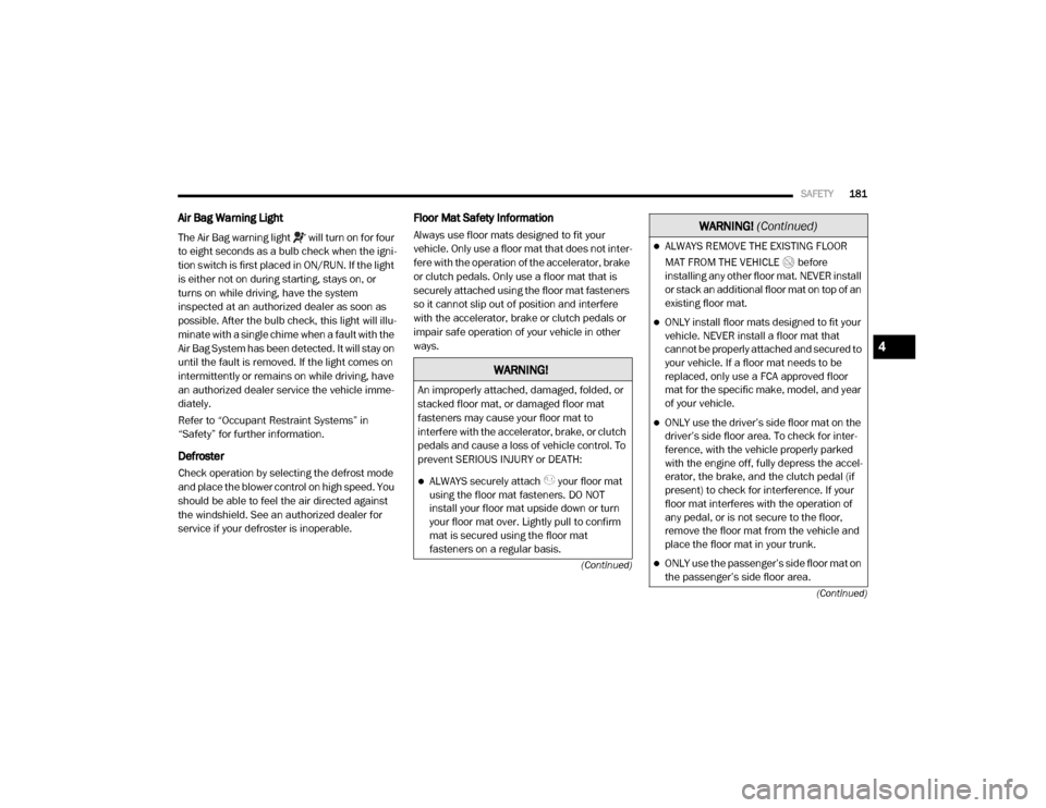
Air Bag Warning Light
The Air Bag warning light will turn on for four
to eight seconds as a bulb check when the igni
-
tion switch is first placed in ON/RUN. If the light
is either not on during starting, stays on, or
turns on while driving, have the system
inspected at an authorized dealer as soon as
possible. After the bulb check, this light will illu -
minate with a single chime when a fault with the
Air Bag System has been detected. It will stay on
until the fault is removed. If the light comes on
intermittently or remains on while driving, have
an authorized dealer service the vehicle imme -
diately.
Refer to “Occupant Restraint Systems” in
“Safety” for further information.
Defroster
Check operation by selecting the defrost mode
and place the blower control on high speed. You
should be able to feel the air directed against
the windshield. See an authorized dealer for
service if your defroster is inoperable.
Floor Mat Safety Information
Always use floor mats designed to fit your
vehicle. Only use a floor mat that does not inter -
fere with the operation of the accelerator, brake
or clutch pedals. Only use a floor mat that is
securely attached using the floor mat fasteners
so it cannot slip out of position and interfere
with the accelerator, brake or clutch pedals or
impair safe operation of your vehicle in other
ways.
WARNING!
An improperly attached, damaged, folded, or
stacked floor mat, or damaged floor mat
fasteners may cause your floor mat to
interfere with the accelerator, brake, or clutch
pedals and cause a loss of vehicle control. To
prevent SERIOUS INJURY or DEATH:
ALWAYS securely attach your floor mat
using the floor mat fasteners. DO NOT
install your floor mat upside down or turn
your floor mat over. Lightly pull to confirm
mat is secured using the floor mat
fasteners on a regular basis.
ALWAYS REMOVE THE EXISTING FLOOR
MAT FROM THE VEHICLE before
installing any other floor mat. NEVER install
or stack an additional floor mat on top of an
existing floor mat.
ONLY install floor mats designed to fit your
vehicle. NEVER install a floor mat that
cannot be properly attached and secured to
your vehicle. If a floor mat needs to be
replaced, only use a FCA approved floor
mat for the specific make, model, and year
of your vehicle.
ONLY use the driver’s side floor mat on the
driver’s side floor area. To check for inter -
ference, with the vehicle properly parked
with the engine off, fully depress the accel -
erator, the brake, and the clutch pedal (if
present) to check for interference. If your
floor mat interferes with the operation of
any pedal, or is not secure to the floor,
remove the floor mat from the vehicle and
place the floor mat in your trunk.
ONLY use the passenger’s side floor mat on
the passenger’s side floor area.
WARNING! (Continued)
4
2020_RAM_CHASSIS_CAB_OM_USA=GUID-6C67832B-7839-4CCF-BEFC-CDF988F949EA=1=en=.book Page 181