headlamp Ram 4500 Chassis Cab 2020 Owner's Manual
[x] Cancel search | Manufacturer: RAM, Model Year: 2020, Model line: 4500 Chassis Cab, Model: Ram 4500 Chassis Cab 2020Pages: 516, PDF Size: 29.24 MB
Page 5 of 516
3
EXTERIOR LIGHTS ...............................................44 Multifunction Lever ...................................... 44
Headlight Switch .......................................... 44
Daytime Running Lights (DRLs) ................. 45
High/Low Beam Switch ............................... 45
Automatic High Beam Headlamp
Control — If Equipped .................................. 45 Flash-To-Pass ............................................. 46
Automatic Headlights — If Equipped .......... 46
Parking Lights And Panel Lights ................. 46
Directional LED Headlamp System —
If Equipped ................................................... 46 Headlights On With Wipers (Available With
Automatic Headlights Only) ......................... 46 Headlight Delay ............................................ 47
Lights-On Reminder ..................................... 47
Front Fog Lights — If Equipped .................. 47
Turn Signals ............................................. 47
Lane Change Assist — If Equipped ............. 47
Cargo Lights/Trailer Spotter Lights —
If Equipped ................................................... 47 Battery Saver................................................ 48
INTERIOR LIGHTS ................................................48
Courtesy Lights ............................................ 48
Illuminated Entry ......................................... 49
WINDSHIELD WIPERS AND WASHERS ............50
Windshield Wipers ..................................... 50
Rain Sensing Wipers — If Equipped ........... 51 CLIMATE CONTROLS ........................................... 51
Manual Climate Control Overview ............ 52
Automatic Climate Control Overview .......... 55
Climate Control Functions........................... 62
Automatic Temperature Control (ATC) ...... 62
Operating Tips ............................................. 63
WINDOWS ............................................................ 64
Power Windows — If Equipped .................... 64
Wind Buffeting ............................................ 66
HOOD .................................................................... 66
To Open The Hood ...................................... 66
To Close The Hood ....................................... 67
GARAGE DOOR OPENER — IF EQUIPPED ........ 67
Before You Begin Programming
HomeLink® .................................................. 68 Canadian/Gate Operator Programming ..... 70
Using HomeLink®........................................ 71
Security......................................................... 71
Troubleshooting Tips ................................... 71
General Information .................................... 72
INTERNAL EQUIPMENT ........................................ 72
Storage ......................................................... 72
Cupholders .................................................. 77
Electrical Power Outlets ............................ 78
Power Inverter — If Equipped ..................... 80
Wireless Charging Pad — If Equipped ........ 81
Overhead Sunglass Storage ....................... 81
GETTING TO KNOW YOUR INSTRUMENT PANEL
BASE / MIDLINE INSTRUMENT CLUSTER..........82Base / Midline Instrument Cluster
Descriptions ................................................. 83
PREMIUM INSTRUMENT CLUSTER .....................85
Premium Instrument Cluster
Descriptions ................................................. 86
DIESEL INSTRUMENT CLUSTER .........................87
DIESEL INSTRUMENT CLUSTER ................ 88
INSTRUMENT CLUSTER .......................................90
Diesel INSTRUMENT CLUSTER .................. 91
INSTRUMENT CLUSTER DISPLAY .......................92
Instrument Cluster Display Controls .......... 92
Oil Life Reset ............................................... 93
Display Menu Items ..................................... 94
Diesel Messages And Warnings —
6.7L Cummins Diesel Engine ................... 103 Battery Saver On/Battery Saver Mode
Message — Electrical Load Reduction Actions
— If Equipped .......................................... 107
WARNING LIGHTS AND MESSAGES ............... 108
Red Warning Lights ................................... 108
Yellow Warning Lights ............................... 111Yellow Indicator Lights .............................. 115
Green Indicator Lights ............................... 116White Indicator Lights ............................... 117Blue Indicator Lights ................................. 118
2020_RAM_CHASSIS_CAB_OM_USA=GUID-6C67832B-7839-4CCF-BEFC-CDF988F949EA=1=en=.book Page 3
Page 47 of 516
GETTING TO KNOW YOUR VEHICLE45
Daytime Running Lights (DRLs)
The headlights on your vehicle will illuminate
when the engine is started and the transmis -
sion is in any gear except PARK. This provides a
constant "lights on" condition until the ignition is
placed in the OFF position. The lights illuminate
at less than half of normal intensity. If the
parking brake is applied, the Daytime Running
Lights (DRLs) will turn off. Also, if a turn signal is
activated, the DRL lamp on the same side of the
vehicle may turn off for the duration of the turn
signal activation. Once the turn signal is no
longer active, the DRL lamp will illuminate.
NOTE:
If allowed by law in the country in which the
vehicle was purchased, the Daytime Running
Lights can be turned on and off using the
Uconnect System, refer to “Uconnect Settings”
in “Multimedia” for further information.
High/Low Beam Switch
Push the multifunction lever toward the instru-
ment panel to switch the headlights to high
beam. Pulling the multifunction lever back
toward the steering wheel will turn the low
beams back on, or shut the high beams off.
Automatic High Beam Headlamp Control —
If Equipped
The Automatic High Beam Headlamp Control
system provides increased forward lighting at
night by automating high beam control through
the use of a digital camera mounted on the
inside rearview mirror or forward facing camera.
This camera detects vehicle specific light and
automatically switches from high beams to low
beams until the approaching vehicle is out of
view.
NOTE:
The Automatic High Beam Headlamp Control
can be turned on or off by selecting “ON”
under “Auto Dim High Beams” within your
Uconnect settings, as well as turning the
headlight switch to the AUTO position. Refer
to “Uconnect Settings” in “Multimedia” for
further information.
Broken, muddy, or obstructed headlights and
taillights of vehicles in the field of view will
cause headlights to remain on longer (closer
to the vehicle). Also, dirt, film, and other
obstructions on the windshield or camera
lens will cause the system to function improp -
erly.
To opt out of the Advanced Auto High Beam
Sensitivity Control (default) and enter
Reduced High Beam Sensitivity Control (not
recommended), on vehicles equipped with
mirror controlled automatic high beams and
without the forward facing camera, toggle the
high beam lever six full on/off cycles within
10 seconds of placing the ignition in the ON
position. The system will return to the default
setting when the ignition is OFF.
If the windshield or Automatic High Beam Head -
lamp Control mirror is replaced, the mirror must
be re-aimed to ensure proper performance. See
a local authorized dealer.
To Activate
1. The Automatic High Beams are enabled through the Uconnect system. Refer to
“Uconnect Settings” in “Multimedia” for
further information.
2. Turn the headlight switch to the AUTO head -
light position.
3. Push the multifunction lever away from you (toward front of vehicle) to engage the high
beam mode.
2
2020_RAM_CHASSIS_CAB_OM_USA=GUID-6C67832B-7839-4CCF-BEFC-CDF988F949EA=1=en=.book Page 45
Page 48 of 516
46GETTING TO KNOW YOUR VEHICLE
NOTE:
The Automatic High Beams will not activate until
the vehicle is at or above 12 mph (20 km/h).
To Deactivate
1. Pull the multifunction lever toward you (or
rearward in vehicle) to manually deactivate
the system (normal operation of low
beams).
2. Push back on the multifunction lever to reactivate the system.
The Automatic High Beams can also be deacti -
vated through the Uconnect system. Refer to
“Uconnect Settings” in “Multimedia” for further
information.
Flash-To-Pass
You can signal another vehicle with your head -
lights by lightly pulling the multifunction lever
toward you. This will cause the high beam head -
lights to turn on, and remain on, until the lever
is released.
Automatic Headlights — If Equipped
This system automatically turns your headlights
on or off based on ambient light levels. To turn
the system on, turn the headlight switch clock-
wise, aligning the indicator with the AUTO on the
headlight switch. When the system is on, the
Headlight Time Delay feature is also on. This
means your headlights will stay on for up to 90
seconds after you place the ignition switch in
the OFF position. To turn the Automatic System
off, turn the headlight switch counterclockwise
to the O (off) position.
NOTE:
The engine must be running before the head -
lights will come on in the Automatic mode.
Parking Lights And Panel Lights
To turn on the parking lights and instrument
panel lights, from the O (off) position, rotate the
headlight switch clockwise to the first detent. To
turn off the parking lights, rotate the headlight
switch back to the O (off) position.
Directional LED Headlamp System — If
Equipped
This is a system consisting of LED (low/high
beam) headlights that incorporate dynamic
cornering with 5-degree inboard/15-degree
outboard swivel. The headlights continuously
and automatically adapt to the driving condi -
tions around bends or when cornering based on
steering wheel angle.
The system directs the headlights to light up the
road in the best way, taking into account the
speed of the vehicle and the bend or corner
angle, as well as the speed of steering.
The adaptive lights are automatically activated
when the vehicle is traveling above approxi -
mately 5 mph (8 km/h).
Headlights On With Wipers (Available With
Automatic Headlights Only)
When this feature is active, the headlights will
turn on approximately 10 seconds after the
wipers are turned on if the headlight switch is
placed in the AUTO position. In addition, the
headlights will turn off when the wipers are
turned off, if they were turned on by this feature.
2020_RAM_CHASSIS_CAB_OM_USA=GUID-6C67832B-7839-4CCF-BEFC-CDF988F949EA=1=en=.book Page 46
Page 160 of 516

158SAFETY
(Continued)
Enhanced Accident Response System
In the event of an impact, if the communication
network remains intact, and the power remains
intact, depending on the nature of the event,
the ORC will determine whether to have the
Enhanced Accident Response System perform
the following functions:
Cut off fuel to the engine (If Equipped)
Cut off battery power to the electric motor (If
Equipped)
Flash hazard lights as long as the battery has
power
Turn on the interior lights, which remain on
as long as the battery has power or for
15 minutes from the intervention of the
Enhanced Accident Response System.
Unlock the power door locks.
Your vehicle may also be designed to perform
any of these other functions in response to the
Enhanced Accident Response System:
Turn off the Fuel Filter Heater, Turn off the
HVAC Blower Motor, Close the HVAC Circula -
tion Door
Cut off battery power to the:
Engine
Electric Motor (if equipped)
Electric power steering
Brake booster
Electric park brake
Automatic transmission gear selector
Horn
Front wiper
Headlamp washer pump
NOTE:
After an accident, remember to place the igni -
tion to the STOP (OFF/LOCK) position and
remove the key from the ignition switch to avoid
draining the battery. Carefully check the vehicle
for fuel leaks in the engine compartment and on
the ground near the engine compartment and
fuel tank before resetting the system and
starting the engine. If there are no fuel leaks or
damage to the vehicle electrical devices (e.g.
headlights) after an accident, reset the system
by following the procedure described below. If
you have any doubt, contact an authorized
dealer.
Enhanced Accident Response System Reset
Procedure
In order to reset the Enhanced Accident
Response System functions after an event, the
ignition switch must be changed from ignition
START or ON/RUN to ignition OFF. Carefully
check the vehicle for fuel leaks in the engine
compartment and on the ground near the
engine compartment and fuel tank before reset -
ting the system and starting the engine.
Maintaining Your Air Bag System
WARNING!
Modifications to any part of the air bag
system could cause it to fail when you need
it. You could be injured if the air bag system
is not there to protect you. Do not modify
the components or wiring, including adding
any kind of badges or stickers to the
steering wheel hub trim cover or the upper
passenger side of the instrument panel. Do
not modify the front bumper, vehicle body
structure, or add aftermarket side steps or
running boards.
2020_RAM_CHASSIS_CAB_OM_USA=GUID-6C67832B-7839-4CCF-BEFC-CDF988F949EA=1=en=.book Page 158
Page 196 of 516

194STARTING AND OPERATING
NORMAL OPERATION — DIESEL ENGINE
Observe the following when the engine is oper -
ating.
All message center lights are off.
Malfunction Indicator Light (MIL) is off.
Engine oil pressure is above 10 psi (69 kPa)
at idle.
Voltmeter operation:
The voltmeter may show a gauge fluctuation at
various engine temperatures. This cycling oper -
ation is caused by the post-heat cycle of the
intake manifold heater system. The number of
cycles and the length of the cycling operation is
controlled by the engine control module.
Post-heat operation can run for several
minutes, and then the electrical system and
voltmeter needle will stabilize. The cycling action will cause temporary
dimming of the headlamps, interior lamps, and
also a noticeable reduction in blower motor
speed.
Cold Weather Precautions
Operation in ambient temperature below 32°F
(0°C) may require special considerations. The
following charts suggest these options:
WARNING!
Do not leave children or animals inside
parked vehicles in hot weather. Interior
heat build up may cause serious injury or
death.
When leaving the vehicle, always remove
the key fob and lock your vehicle.
Never leave children alone in a vehicle, or
with access to an unlocked vehicle.
Allowing children to be in a vehicle unat
-
tended is dangerous for a number of
reasons. A child or others could be seriously
or fatally injured. Children should be
warned not to touch the parking brake,
brake pedal or the gear selector. Do not
leave the key fob in or near the vehicle (or
in a location accessible to children), and do
not leave the ignition of a vehicle equipped
with Keyless Enter-N-Go in the ACC or ON/
RUN mode. A child could operate power
windows, other controls, or move the
vehicle.
2020_RAM_CHASSIS_CAB_OM_USA=GUID-6C67832B-7839-4CCF-BEFC-CDF988F949EA=1=en=.book Page 194
Page 203 of 516
STARTING AND OPERATING201
Diesel Particulate Filter (DPF) Manual
Regeneration - If Equipped
On equipped chassis cabs, a manual regenera -
tion can be enable through the instrument
cluster. The manual regeneration will allow the
DPF to complete a regeneration, lowering the
soot level without having to drive the vehicle.
The vehicle must be in park to access this
feature, and the fuel level must be over 12.5%
full. A message displaying the time left on the
regeneration will appear on the instrument
cluster, and the instrument cluster will display
the soot level. Refer to “Instrument Cluster
Display” in “Getting to Know Your Instrument
Panel” for further information.
ENGINE BLOCK HEATER — IF EQUIPPED
The engine block heater warms the engine, and
permits quicker starts in cold weather. Connect
the cord to a standard 110-115 Volt AC elec -
trical outlet with a grounded, three-wire exten -
sion cord.
Gas Engine Only
The engine block heater cord is routed through
the grille by the right front tow hook. It includes a removable cap that is secured by a
tethered strap. It also has a c-clip that is used
for storage when not in use for the Winter
months. During Winter months, remove the
heater cord wiring assembly from itself on the
c-clip.
The engine block heater must be plugged in at
least one hour to have an adequate warming
effect on the engine.
Diesel Engine Only
The engine block heater warms engine coolant
and permits quicker starts in cold weather.
Connect the heater cord to a ground-fault inter
-
rupter protected 110–115 Volt AC electrical
outlet with a grounded, three-wire extension
cord.
The engine block heater cord is routed under
the hood to the right side and can be located
just behind the grille near the headlamp. NOTE:
The engine block heater cord is a factory
installed option. If your vehicle is not equipped,
heater cords are available from an authorized
Mopar dealer.
The block heater must be plugged in at least
one hour to have an adequate warming effect
on the coolant.
NOTE:
The block heater will require 110 Volts AC and
6.5 Amps to activate the heater element.
Block Heater Usage
For ambient temperatures below 0°F (-18°C),
engine block heater usage is recommended.
For ambient temperatures below –20°F
(-29°C), engine block heater usage is required.
WARNING!
Remember to disconnect the engine block
heater cord before driving. Damage to the
110-115 Volt electrical cord could cause
electrocution.
WARNING!
Remember to disconnect the engine block
heater cord before driving. Damage to the
110-115 Volt electrical cord could cause
electrocution.5
2020_RAM_CHASSIS_CAB_OM_USA=GUID-6C67832B-7839-4CCF-BEFC-CDF988F949EA=1=en=.book Page 201
Page 269 of 516
STARTING AND OPERATING267
AUX Camera — If Equipped
Your vehicle may be equipped with one or two
AUX Cameras, which display a rearview image
from the trailer on the touchscreen.
Activation
The AUX Camera is activated by first pressing
the Backup Camera, Cargo Camera (if
equipped), or Surround View Camera (if
equipped) button on the touchscreen, followed
by the AUX button located in the upper left
corner of the rearview display. The AUX camera
can also be activated when the vehicle is in
REVERSE by pressing the AUX button.
If equipped with two AUX Cameras, you can
switch between each camera by then pressing
the AUX1 or AUX2 buttons on the Trailer Camera
display.
AUX1 Camera Button
AUX2 Camera Button Deactivation
The AUX Camera is deactivated by pressing the
“X” in the upper right corner of the touchscreen.
This will return the display back to the previ
-
ously displayed screen.
NOTE:
If the AUX button is pressed and no AUX
Camera is connected, the touchscreen will
display a blue screen along with the message
“Camera System Unavailable.” The screen
can be exited out by pressing the “X” in the
upper right hand corner. This will return the
display back to the previously displayed
screen.
Zoom View is not available with the AUX
Camera feature.
The display will always default to the Trailer
Camera display (AUX 1).
ENGINE RUNAWAY
Diesel engine runaway is a rare condition
affecting diesel engines, where the engine
consumes its own lubrication oil and runs at
higher and higher RPM until it overspeeds to a
point where it destroys itself due to either
mechanical failure or engine seizure through
lack of lubrication.
WARNING!
In case of engine runaway due to flammable
fumes from fuel spills or turbocharger oil
leaks being sucked into the engine, do the
following to help avoid personal injury and/or
vehicle damage:
Turn the ignition switch to the OFF position.
Using a CO2 or dry chemical type fire extin -
guisher, direct the spray from the fire extin -
guisher into the grille on the passenger side
so that the spray enters the engine air
intake.
The inlet for the engine air intake is located
behind the passenger side headlamp and
receives air through the grille.
5
2020_RAM_CHASSIS_CAB_OM_USA=GUID-6C67832B-7839-4CCF-BEFC-CDF988F949EA=1=en=.book Page 267
Page 302 of 516
300IN CASE OF EMERGENCY
BULB REPLACEMENT
Replacement Bulbs
All of the inside bulbs are brass or glass-wedge base. Aluminum base bulbs are not approved.
Interior Bulbs
Bulb Name Bulb Number
Overhead Console Lamps TS 212–9
Dome Lamp 7679
NOTE:
For lighted switches, see an authorized dealer for replacement instructions.
Exterior Bulbs
Bulb Name Bulb Number
Low Beam (Halogen Reflector Headlamp) H11LL
High Beam (Halogen Reflector Headlamp) 9005LL
Low & High Beam (LED Reflector Headlamp) LED (Serviced At An Authorized Dealer)
Low & High Beam (LED Projector Headlamp) LED (Serviced At An Authorized Dealer)
Turn Signal / Front Position (Halogen Reflector Headlamp) 7444NA
Turn Signal / Front Position (LED Headlamps) LED (Serviced At An Authorized Dealer)
Front Side Marker (Halogen Reflector Headlamp) W5W
Front Side Marker (LED Headlamps) LED (Serviced At An Authorized Dealer)
Front Fog Lamps (Halogen Reflector Headlamp) H11LL
2020_RAM_CHASSIS_CAB_OM_USA=GUID-6C67832B-7839-4CCF-BEFC-CDF988F949EA=1=en=.book Page 300
Page 303 of 516
IN CASE OF EMERGENCY301
Replacing Exterior Bulbs
Base Quad: Low Beam Headlamp, High
Beam Headlamp, Front Park And Turn — If
Equipped
Low Beam
1. Open the hood.
2. Disconnect and isolate the negative battery
cable.
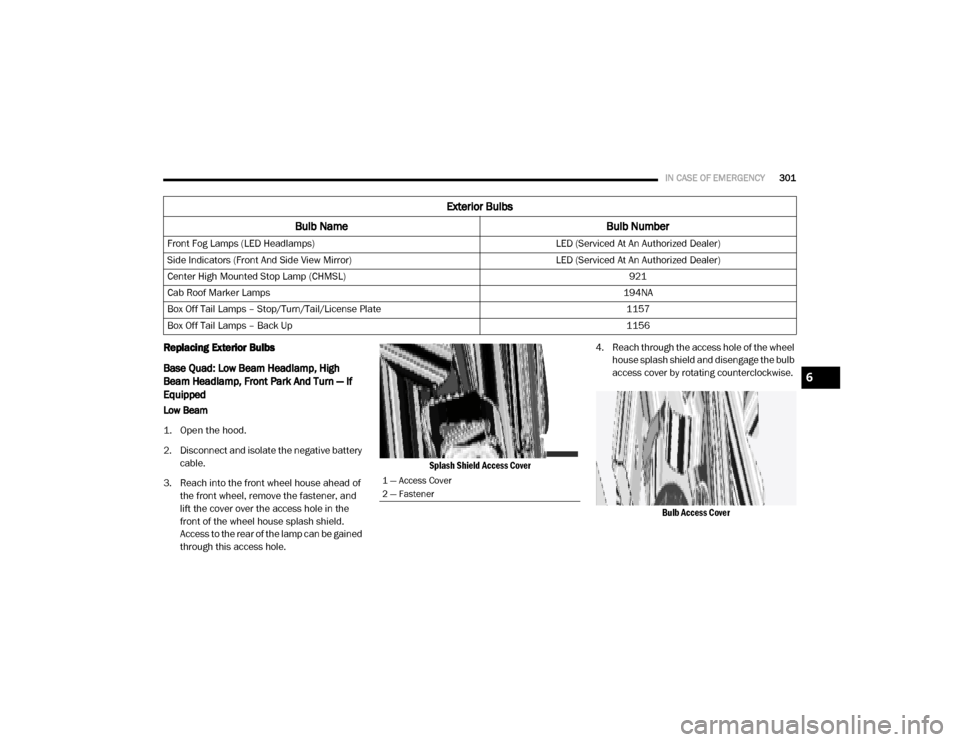
3. Reach into the front wheel house ahead of the front wheel, remove the fastener, and
lift the cover over the access hole in the
front of the wheel house splash shield.
Access to the rear of the lamp can be gained
through this access hole.
Splash Shield Access Cover
4. Reach through the access hole of the wheel
house splash shield and disengage the bulb
access cover by rotating counterclockwise.
Bulb Access Cover
Front Fog Lamps (LED Headlamps)
LED (Serviced At An Authorized Dealer)
Side Indicators (Front And Side View Mirror) LED (Serviced At An Authorized Dealer)
Center High Mounted Stop Lamp (CHMSL) 921
Cab Roof Marker Lamps 194NA
Box Off Tail Lamps – Stop/Turn/Tail/License Plate 1157
Box Off Tail Lamps – Back Up 1156
Exterior Bulbs
Bulb Name Bulb Number
1 — Access Cover
2 — Fastener
6
2020_RAM_CHASSIS_CAB_OM_USA=GUID-6C67832B-7839-4CCF-BEFC-CDF988F949EA=1=en=.book Page 301
Page 304 of 516
302IN CASE OF EMERGENCY
5. Disconnect the internal lamp wiring harness
connector from the low beam bulb.
6. Rotate the bulb counterclockwise a quarter turn to unlock the bulb from the lamp.
7. Pull the bulb straight out from the housing.
8. Reverse the procedure for installation of new bulb and covers.
High Beam
1. Open the hood.
2. Disconnect and isolate the negative battery cable. 3. Look under the hood and behind the head
-
lamp to find the high beam bulb access
cover.
4. Reach behind the headlamp and disengage the access cover by rotating counterclock -
wise.
5. Disconnect the internal lamp wiring harness connector from the high beam bulb.
6. Rotate the bulb counterclockwise a quarter turn to unlock the bulb from the lamp.
7. Pull the bulb straight out from the housing.
8. Reverse the procedure for installation of new bulb and covers. Front Park And Turn
1. Open the hood.
2. Disconnect and isolate the negative battery
cable.
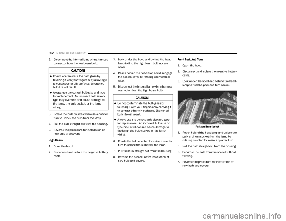
3. Look under the hood and behind the head -
lamp to find the park and turn socket.
Park And Turn Socket
4. Reach behind the headlamp and unlock the park and turn socket from the lamp by
rotating counterclockwise a quarter turn.
5. Pull the bulb straight out from the housing.
6. Separate the bulb from the socket without twisting.
7. Reverse the procedure for installation of new bulb and covers.
CAUTION!
Do not contaminate the bulb glass by
touching it with your fingers or by allowing it
to contact other oily surfaces. Shortened
bulb life will result.
Always use the correct bulb size and type
for replacement. An incorrect bulb size or
type may overheat and cause damage to
the lamp, the bulb socket, or the lamp
wiring.
2020_RAM_CHASSIS_CAB_OM_USA=GUID-6C67832B-7839-4CCF-BEFC-CDF988F949EA=1=en=.book Page 302