Ram 5500 Chassis Cab 2017 Owner's Manual
Manufacturer: RAM, Model Year: 2017, Model line: 5500 Chassis Cab, Model: Ram 5500 Chassis Cab 2017Pages: 534, PDF Size: 4.74 MB
Page 231 of 534

Trip A/Trip B
Push and release theUPorDOWNarrow button
until the Trip menu item is highlighted in the Instru-
ment Cluster Display. Push and release the RIGHT
arrow button to enter the submenus of Trip A and
Trip B. The Trip A or Trip B information will display the
following:
• Distance
• Average MPG
• Elapsed Time
Push and hold RIGHT
arrow button to reset all
information.
Trailer Tow
Push and release the UPorDOWNarrow button
until the Trailer Tow menu item is highlighted in the
Instrument Cluster Display. Push and release the
RIGHT
arrow button and the next screen will dis-
play the following trailer trip information:
• Trip (trailer specific) Distance: Push and hold the
RIGHT
arrow button to reset the distance.
• Trailer Brake
• Output
• Type
• Gain
Audio
Push and release the UPorDOWNarrow button
until the Audio display icon is highlighted in the
Instrument Cluster Display. Push and release the
RIGHT
arrow button to display the active source.
Stored Messages
Push and release the UPorDOWNar-
row button until the Messages Menu item is
highlighted. This feature shows the number of
stored warning messages. Pushing the RIGHT
arrow button will allow you to see what the stored
messages are.
When no messages are present, main menu icon will be a
closed envelope.
4
UNDERSTANDING YOUR INSTRUMENT PANEL 229
Page 232 of 534
Screen Setup Menu Item
Push and release theUPorDOWNarrow button
until the Screen Setup menu item is highlighted in the
Instrument Cluster Display. Push and release the
RIGHT
arrow button to enter the Screen Setup
submenu. The Screen Setup feature allows you to
change what information is displayed in the instrument
cluster as well as the location that information is
displayed.
Vehicle Settings Menu Item
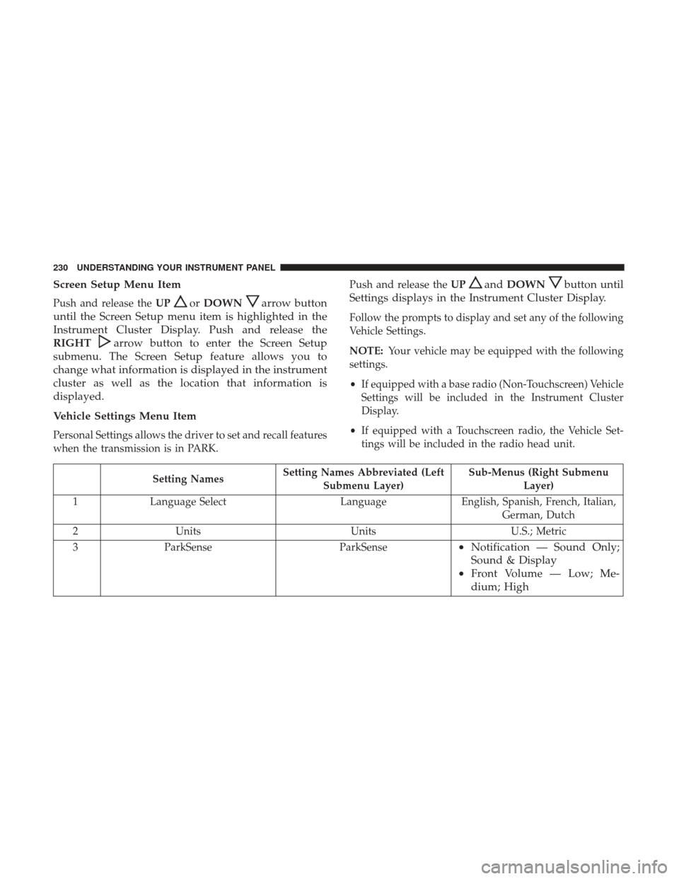
Personal Settings allows the driver to set and recall features
when the transmission is in PARK. Push and release the
UP
andDOWNbutton until
Settings displays in the Instrument Cluster Display.
Follow the prompts to display and set any of the following
Vehicle Settings.
NOTE: Your vehicle may be equipped with the following
settings.
• If equipped with a base radio (Non-Touchscreen) Vehicle
Settings will be included in the Instrument Cluster
Display.
• If equipped with a Touchscreen radio, the Vehicle Set-
tings will be included in the radio head unit.
Setting Names Setting Names Abbreviated (Left
Submenu Layer) Sub-Menus (Right Submenu
Layer)
1 Language Select LanguageEnglish, Spanish, French, Italian,
German, Dutch
2 Units UnitsU.S.; Metric
3 ParkSense ParkSense
•Notification — Sound Only;
Sound & Display
• Front Volume — Low; Me-
dium; High
230 UNDERSTANDING YOUR INSTRUMENT PANEL
Page 233 of 534
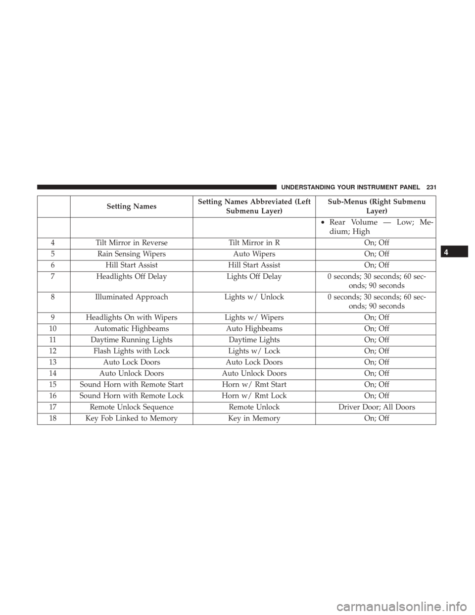
Setting NamesSetting Names Abbreviated (Left
Submenu Layer) Sub-Menus (Right Submenu
Layer)
•Rear Volume — Low; Me-
dium; High
4 Tilt Mirror in Reverse Tilt Mirror in R On; Off
5 Rain Sensing Wipers Auto WipersOn; Off
6 Hill Start Assist Hill Start Assist On; Off
7 Headlights Off Delay Lights Off Delay0 seconds; 30 seconds; 60 sec-
onds; 90 seconds
8 Illuminated Approach Lights w/ Unlock0 seconds; 30 seconds; 60 sec-
onds; 90 seconds
9 Headlights On with Wipers Lights w/ WipersOn; Off
10 Automatic Highbeams Auto Highbeams On; Off
11 Daytime Running Lights Daytime LightsOn; Off
12 Flash Lights with Lock Lights w/ Lock On; Off
13 Auto Lock Doors Auto Lock Doors On; Off
14 Auto Unlock Doors Auto Unlock Doors On; Off
15 Sound Horn with Remote Start Horn w/ Rmt StartOn; Off
16 Sound Horn with Remote Lock Horn w/ Rmt LockOn; Off
17 Remote Unlock Sequence Remote UnlockDriver Door; All Doors
18 Key Fob Linked to Memory Key in MemoryOn; Off
4
UNDERSTANDING YOUR INSTRUMENT PANEL 231
Page 234 of 534
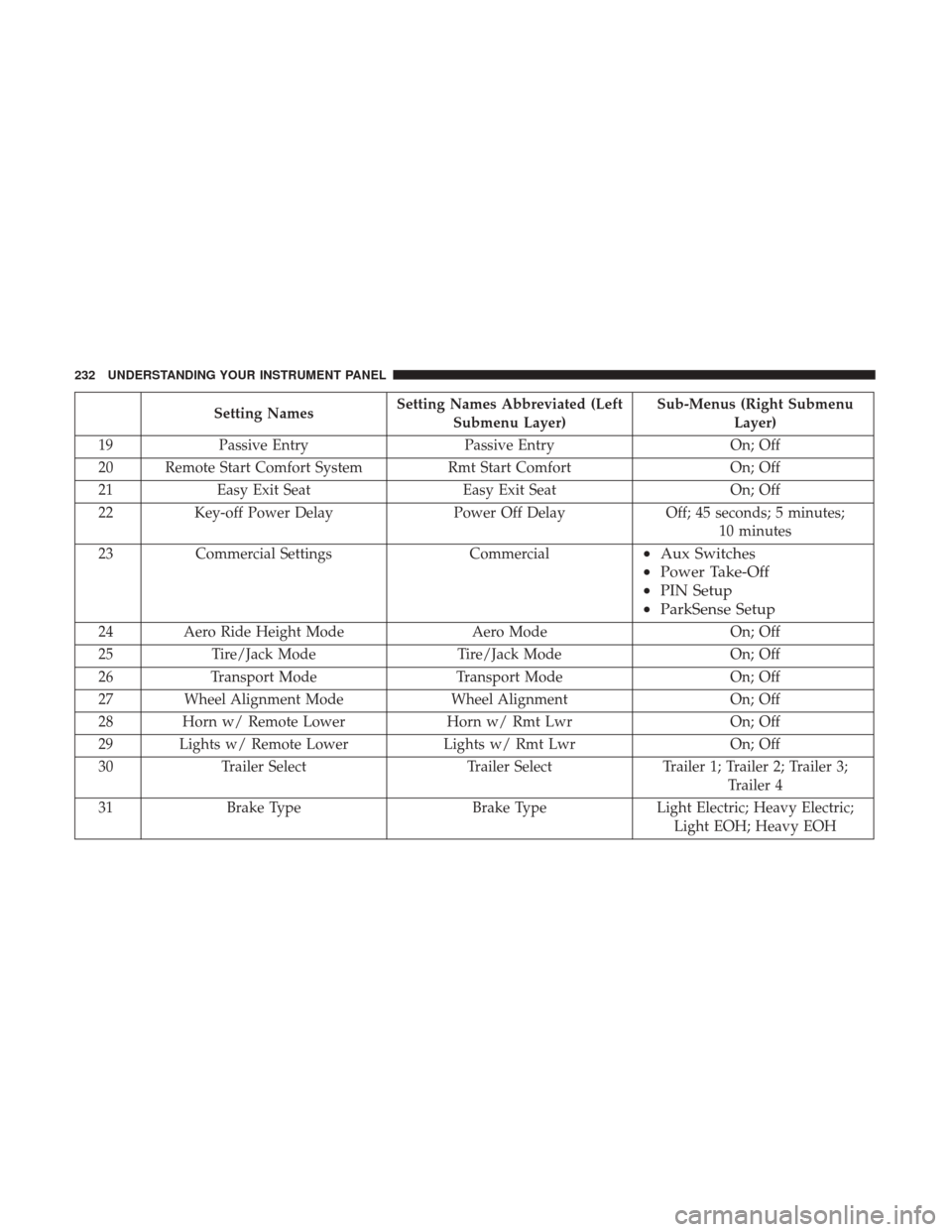
Setting NamesSetting Names Abbreviated (Left
Submenu Layer) Sub-Menus (Right Submenu
Layer)
19 Passive Entry Passive Entry On; Off
20 Remote Start Comfort System Rmt Start ComfortOn; Off
21 Easy Exit Seat Easy Exit Seat On; Off
22 Key-off Power Delay Power Off DelayOff; 45 seconds; 5 minutes;
10 minutes
23 Commercial Settings Commercial
•Aux Switches
• Power Take-Off
• PIN Setup
• ParkSense Setup
24 Aero Ride Height Mode Aero ModeOn; Off
25 Tire/Jack Mode Tire/Jack Mode On; Off
26 Transport Mode Transport Mode On; Off
27 Wheel Alignment Mode Wheel AlignmentOn; Off
28 Horn w/ Remote Lower Horn w/ Rmt LwrOn; Off
29 Lights w/ Remote Lower Lights w/ Rmt LwrOn; Off
30 Trailer Select Trailer SelectTrailer 1; Trailer 2; Trailer 3;
Trailer 4
31 Brake Type Brake TypeLight Electric; Heavy Electric;
Light EOH; Heavy EOH
232 UNDERSTANDING YOUR INSTRUMENT PANEL
Page 235 of 534

Setting NamesSetting Names Abbreviated (Left
Submenu Layer) Sub-Menus (Right Submenu
Layer)
32 Trailer Name Trailer Name
•Trailer # (# is equal to slot
position)
• Boat
• Car
• Cargo
• Dump
• Equipment
• Flatbed
• Gooseneck
• Horse
• Ta g
• Motorcycle
• Snowmobile
• Travel
• Utility
• 5th Wheel
33 Compass Variance Compass Var1-15 increments of 1
34 Calibrate Compass Compass CalCancel; Calibrate
4
UNDERSTANDING YOUR INSTRUMENT PANEL 233
Page 236 of 534
Turn Menu OFF — If Equipped
Push and release theRIGHTarrow button to exit the
main menu.
Push and release any Instrument Cluster Display control
button to enter the Instrument Cluster Display main menu
again.
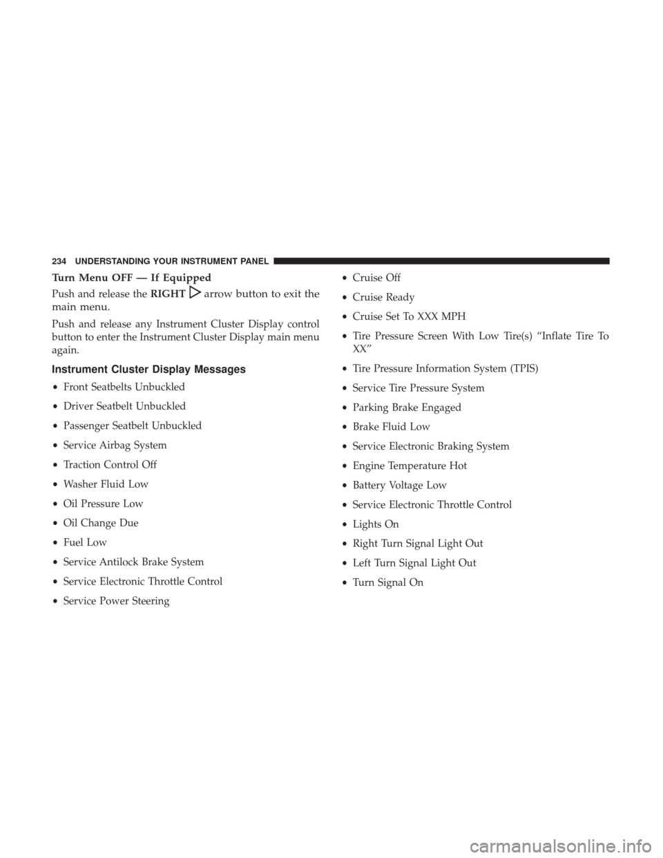
Instrument Cluster Display Messages
• Front Seatbelts Unbuckled
• Driver Seatbelt Unbuckled
• Passenger Seatbelt Unbuckled
• Service Airbag System
• Traction Control Off
• Washer Fluid Low
• Oil Pressure Low
• Oil Change Due
• Fuel Low
• Service Antilock Brake System
• Service Electronic Throttle Control
• Service Power Steering •
Cruise Off
• Cruise Ready
• Cruise Set To XXX MPH
• Tire Pressure Screen With Low Tire(s) “Inflate Tire To
XX”
• Tire Pressure Information System (TPIS)
• Service Tire Pressure System
• Parking Brake Engaged
• Brake Fluid Low
• Service Electronic Braking System
• Engine Temperature Hot
• Battery Voltage Low
• Service Electronic Throttle Control
• Lights On
• Right Turn Signal Light Out
• Left Turn Signal Light Out
• Turn Signal On
234 UNDERSTANDING YOUR INSTRUMENT PANEL
Page 237 of 534
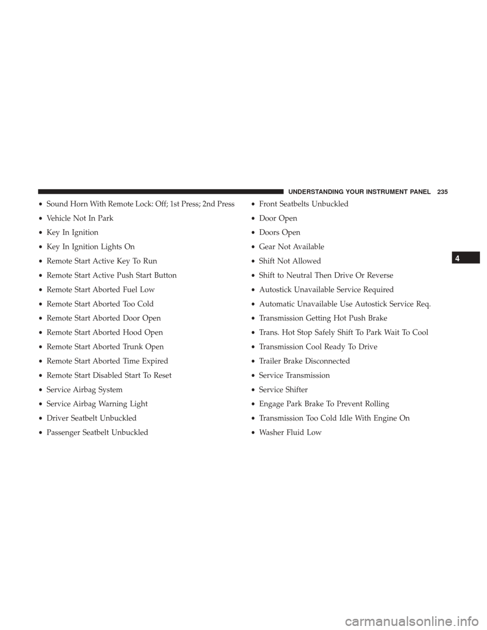
•Sound Horn With Remote Lock: Off; 1st Press; 2nd Press
• Vehicle Not In Park
• Key In Ignition
• Key In Ignition Lights On
• Remote Start Active Key To Run
• Remote Start Active Push Start Button
• Remote Start Aborted Fuel Low
• Remote Start Aborted Too Cold
• Remote Start Aborted Door Open
• Remote Start Aborted Hood Open
• Remote Start Aborted Trunk Open
• Remote Start Aborted Time Expired
• Remote Start Disabled Start To Reset
• Service Airbag System
• Service Airbag Warning Light
• Driver Seatbelt Unbuckled
• Passenger Seatbelt Unbuckled •
Front Seatbelts Unbuckled
• Door Open
• Doors Open
• Gear Not Available
• Shift Not Allowed
• Shift to Neutral Then Drive Or Reverse
• Autostick Unavailable Service Required
• Automatic Unavailable Use Autostick Service Req.
• Transmission Getting Hot Push Brake
• Trans. Hot Stop Safely Shift To Park Wait To Cool
• Transmission Cool Ready To Drive
• Trailer Brake Disconnected
• Service Transmission
• Service Shifter
• Engage Park Brake To Prevent Rolling
• Transmission Too Cold Idle With Engine On
• Washer Fluid Low
4
UNDERSTANDING YOUR INSTRUMENT PANEL 235
Page 238 of 534

The Reconfigurable Telltales section is divided into the
white telltales area on the right, yellow telltales in the
middle, and red telltales on the left.
Battery Saver On/Battery Saver Mode Message —
Electrical Load Reduction Actions — If Equipped
This vehicle is equipped with an Intelligent Battery Sensor
(IBS) to perform additional monitoring of the electrical
system and status of the vehicle battery.
In cases when the IBS detects charging system failure, or
the vehicle battery conditions are deteriorating, electrical
load reduction actions will take place to extend the driving
time and distance of the vehicle. This is done by reducing
power to or turning off non-essential electrical loads.
Load reduction is only active when the engine is running.
It will display a message if there is a risk of battery
depletion to the point where the vehicle may stall due to
lack of electrical supply, or will not restart after the current
drive cycle.
When load reduction is activated, the message “Battery
Saver On” or “Battery Saver Mode” will appear in the
Instrument Cluster.These messages indicate the vehicle battery has a low state
of charge and continues to lose electrical charge at a rate
that the charging system cannot sustain.
NOTE:
•
The charging system is independent from load reduc-
tion. The charging system performs a diagnostic on the
charging system continuously.
• If the Battery Charge Warning Light is on it may indicate
a problem with the charging system. Refer to “Battery
Charge Warning Light” in “Understanding Your Instru-
ment Panel” for further information.
The electrical loads that may be switched off (if equipped),
and vehicle functions which can be effected by load
reduction:
• Heated Seat/Vented Seats/Heated Wheel
• Heated/Cooled Cup Holders — If Equipped
• Rear Defroster And Heated Mirrors
• HVAC System
• 115V AC Power Inverter System
• Audio and Telematics System
236 UNDERSTANDING YOUR INSTRUMENT PANEL
Page 239 of 534

Loss of the battery charge may indicate one or more of the
following conditions:
•The charging system cannot deliver enough electrical
power to the vehicle system because the electrical loads
are larger than the capability of charging system. The
charging system is still functioning properly.
• Turning on all possible vehicle electrical loads (e.g.
HVAC to max settings, exterior and interior lights,
overloaded power outlets +12V, 115V AC, USB ports)
during certain driving conditions (city driving, towing,
frequent stopping).
• Installing options like additional lights, upfitter electri-
cal accessories, audio systems, alarms and similar de-
vices.
• Unusual driving cycles (short trips separated by long
parking periods).
• The vehicle was parked for an extended period of time
(weeks, months).
• The battery was recently replaced and was not charged
completely.
• The battery was discharged by an electrical load left on
when the vehicle was parked. •
The battery was used for an extended period with the
engine not running to supply radio, lights, chargers,
+12V portable appliances like vacuum cleaners, game
consoles and similar devices.
What to do when an electrical load reduction action
message is present (“Battery Saver On” or “Battery Saver
Mode”)
During a trip:
• Reduce power to unnecessary loads if possible:
– Turn off redundant lights (interior or exterior)
– Check what may be plugged in to power outlets +12V, 115V AC, USB ports
– Check HVAC settings (blower, temperature)
– Check the audio settings (volume)
After a trip:
• Check if any aftermarket equipment was installed (ad-
ditional lights, upfitter electrical accessories, audio sys-
tems, alarms) and review specifications if any (load and
Ignition Off Draw currents).
• Evaluate the latest driving cycles (distance, driving time
and parking time).
4
UNDERSTANDING YOUR INSTRUMENT PANEL 237
Page 240 of 534

•The vehicle should have service performed if the mes-
sage is still present during consecutive trips and the
evaluation of the vehicle and driving pattern did not
help to identify the cause.
CYBERSECURITY
Your vehicle may be a connected vehicle and may be
equipped with both wired and wireless networks. These
networks allow your vehicle to send and receive informa-
tion. This information allows systems and features in your
vehicle to function properly.
Your vehicle may be equipped with certain security fea-
tures to reduce the risk of unauthorized and unlawful
access to vehicle systems and wireless communications.
Vehicle software technology continues to evolve over time
and FCA US LLC, working with its suppliers, evaluates
and takes appropriate steps as needed. Similar to a com-
puter or other devices, your vehicle may require software
updates to improve the usability and performance of your
systems or to reduce the potential risk of unauthorized and
unlawful access to your vehicle systems.
The risk of unauthorized and unlawful access to your
vehicle systems may still exist, even if the most recent version of vehicle software (such as Uconnect software) is
installed.
WARNING!
•
It is not possible to know or to predict all of the
possible outcomes if your vehicle’s systems are
breached. It may be possible that vehicle systems,
including safety related systems, could be impaired
or a loss of vehicle control could occur that may
result in an accident involving serious injury or
death.
• ONLY insert media (e.g., USB, SD card, or CD) into
your vehicle if it came from a trusted source. Media
of unknown origin could possibly contain malicious
software, and if installed in your vehicle, it may
increase the possibility for vehicle systems to be
breached.
• As always, if you experience unusual vehicle behav-
ior, take your vehicle to your nearest Authorized
Dealer immediately.
NOTE:
• FCA or your dealer may contact you directly regarding
software updates.
238 UNDERSTANDING YOUR INSTRUMENT PANEL