warning light Ram Cargo Van 2014 User Guide
[x] Cancel search | Manufacturer: RAM, Model Year: 2014, Model line: Cargo Van, Model: Ram Cargo Van 2014Pages: 666, PDF Size: 5.09 MB
Page 118 of 666
WARNING!
Vehicles and other objects seen in an outside convex
mirror will look smaller and farther away than they
really are. Relying too much on side convex mirrors
could cause you to collide with another vehicle or
other object. Use your inside mirror when judging
the size or distance of a vehicle seen in a side convex
mirror.
Driver’s Outside Automatic Dimming Mirror — If
Equipped
The driver ’s outside mirror will automatically adjust for
glare from vehicles behind you. This feature is controlled
by the inside automatic dimming mirror and will auto-
matically adjust for headlight glare when the inside
mirror adjusts.
Outside Mirrors Folding Feature
All outside mirrors are hinged and may be moved either
forward or rearward to resist damage. The hinges have
three detent positions:
•Full forward position
• Full rearward position
• Normal position
Power Mirrors — If Equipped
The power mirror controls are located on the driver-side
door trim panel.
116 UNDERSTANDING THE FEATURES OF YOUR VEHICLE
Page 122 of 666
BLIND SPOT MONITORING (BSM) — IF
EQUIPPED
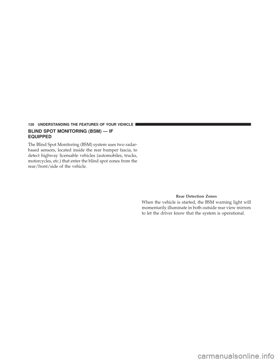
The Blind Spot Monitoring (BSM) system uses two radar-
based sensors, located inside the rear bumper fascia, to
detect highway licensable vehicles (automobiles, trucks,
motorcycles, etc.) that enter the blind spot zones from the
rear/front/side of the vehicle.When the vehicle is started, the BSM warning light will
momentarily illuminate in both outside rear view mirrors
to let the driver know that the system is operational.
Rear Detection Zones
120 UNDERSTANDING THE FEATURES OF YOUR VEHICLE
Page 123 of 666
Automatic Transmission Vehicles
The BSM system sensors operate when the vehicle is in
any forward gear or REVERSE and enters stand-by mode
when the vehicle is in PARK.
Manual Transmission Vehicles
The BSM system sensors operate when the vehicle is in
any gear and enters stand-by mode when the Park Brake
is engaged, the vehicle is not in REVERSE, and the
vehicle is stationary.
The BSM detection zone covers approximately one lane
on both sides of the vehicle (12 ft or 3.8 m). The zone
starts at the outside rear view mirror and extends ap-
proximately 23 ft (7 m) to the rear of the vehicle. The BSM
system monitors the detection zones on both sides of the
vehicle when the vehicle speed reaches approximately
6 mph (10 km/h) or higher and will alert the driver of
vehicles in these areas.NOTE:
•
The BSM system does NOT alert the driver about
rapidly approaching vehicles that are outside the de-
tection zones.
• The BSM system detection zone DOES NOT change if
your vehicle is towing a trailer. Therefore, visually
verify the adjacent lane is clear for both your vehicle
and trailer before making a lane change. If the trailer or
other object (i.e., bicycle, sports equipment) extends
beyond the side of your vehicle, this may result in the
BSM warning light remaining illuminated the entire
time the vehicle is in a forward gear.
3
UNDERSTANDING THE FEATURES OF YOUR VEHICLE 121
Page 124 of 666
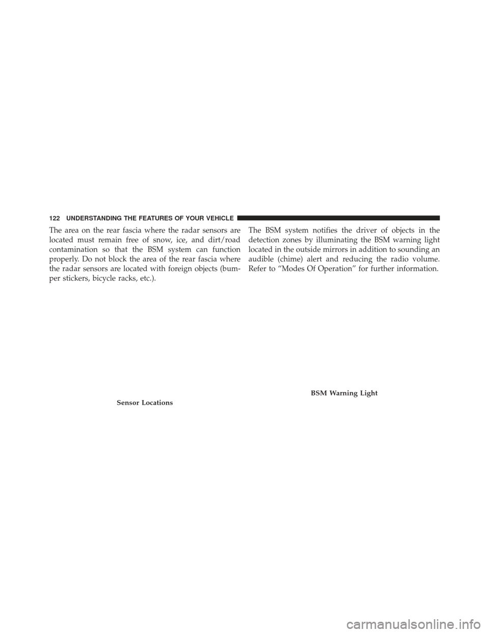
The area on the rear fascia where the radar sensors are
located must remain free of snow, ice, and dirt/road
contamination so that the BSM system can function
properly. Do not block the area of the rear fascia where
the radar sensors are located with foreign objects (bum-
per stickers, bicycle racks, etc.).The BSM system notifies the driver of objects in the
detection zones by illuminating the BSM warning light
located in the outside mirrors in addition to sounding an
audible (chime) alert and reducing the radio volume.
Refer to “Modes Of Operation” for further information.
Sensor Locations
BSM Warning Light
122 UNDERSTANDING THE FEATURES OF YOUR VEHICLE
Page 126 of 666
Entering From The Rear
Vehicles that come up from behind your vehicle on either
side and enter the rear detection zone with a relative
speed of less than 30 mph (48 km/h).Overtaking Traffic
If you pass another vehicle slowly (with a relative speed
of less than 15 mph (24 km/h) and the vehicle remains in
the blind spot for approximately 1.5 seconds, the warning
light will be illuminated. If the difference in speed
between the two vehicles is greater than 15 mph
(24 km/h), the warning light will not illuminate.
Rear Monitoring
Overtaking/Approaching
124 UNDERSTANDING THE FEATURES OF YOUR VEHICLE
Page 145 of 666
•If supported, this number may be programmable on
some systems. To do this, press the
button and say
“Setup,” followed by “Emergency.”
• The Uconnect® Phone does slightly lower your
chances of successfully making a phone call as to that
for the mobile phone directly.
WARNING!
To use your Uconnect® Phone System in an emer-
gency, your mobile phone must be:
• turned on,
• paired to the Uconnect® System,
• and have network coverage.
Roadside Assistance / Towing Assistance
If you need roadside assistance:
• Press the
button to begin. •
After the “Ready” prompt and the following beep, say
“Towing Assistance.”
NOTE: You should program the desired Towing Assis-
tance phone number using the Voice Command system.
To do this, press the button and say “Setup,” followed by
“Towing Assistance.” When prompted say 1-800-528-
2069 for the U.S., say 1-800-363-4869 for Canada, say
55-14-3454 for Mexico City and 1-800-712-3040 for out-
side Mexico City in Mexico.
Paging
To learn how to page, refer to “Working with Automated
Systems”. Paging works properly except for pagers of
certain companies, which time out a little too soon to
work properly with the Uconnect® Phone.
Voice Mail Calling
To learn how to access your voice mail, refer to “Working
with Automated Systems”.
3
UNDERSTANDING THE FEATURES OF YOUR VEHICLE 143
Page 172 of 666
WARNING!
•Persons who are unable to feel pain to the skin
because of advanced age, chronic illness, diabetes,
spinal cord injury, medication, alcohol use, exhaus-
tion or other physical condition must exercise care
when using the seat heater. It may cause burns
even at low temperatures, especially if used for
long periods of time.
• Do not place anything on the seat or seatback that
insulates against heat, such as a blanket or cushion.
This may cause the seat heater to overheat. Sitting
in a seat that has been overheated could cause
serious burns due to the increased surface tempera-
ture of the seat.
Vehicles Equipped With Remote Start
On models that are equipped with remote start, the
driver ’s heated seat can be programmed to come on during a remote start. Refer to “Remote Starting System
— If Equipped” in “Things To Know Before Starting Your
Vehicle” for further information.
Front Heated Seats
There are two heated seat switches that allow the driver
and passenger to operate the seats independently. The
controls for each heater are located on the switch bank
below the climate controls.
You can choose from HIGH, LOW or OFF heat settings.
Amber indicator lights in each switch indicate the level of
heat in use. Two indicator lights will illuminate for
HIGH, one for LOW and none for OFF.
Press the switch once to select HIGH-level
heating. Press the switch a second time to select
LOW-level heating. Press the switch a third
time to shut the heating elements OFF.
170 UNDERSTANDING THE FEATURES OF YOUR VEHICLE
Page 176 of 666
To recline, lean forward slightly, lift the lever, then push
back to the desired position and release the lever. Lean
forward and lift the lever to return the seatback to its
normal position. Using body pressure, lean forward and
rearward on the seat to be sure the seatback has latched.
WARNING!
Do not ride with the seatback reclined so that the
shoulder belt is no longer resting against your chest.
In a collision you could slide under the seat belt,
which could result in serious injury or death.
Head Restraints
Head restraints are designed to reduce the risk of injury
by restricting head movement in the event of a rear
impact. Head restraints should be adjusted so that the top
of the head restraint is located above the top of your ear.
WARNING!
The head restraints for all occupants must be prop-
erly adjusted prior to operating the vehicle or occu-
pying a seat. Head restraints should never be ad-
justed while the vehicle is in motion. Driving a
vehicle with the head restraints improperly adjusted
or removed could cause serious injury or death in the
event of a collision.
Active Head Restraints — Front Seats
Active Head Restraints are passive, deployable compo-
nents, and vehicles with this equipment cannot be readily
identified by any markings, only through visual inspec-
tion of the head restraint. The head restraint will be split
in two halves, with the front half being soft foam and
trim, the back half being decorative plastic.
174 UNDERSTANDING THE FEATURES OF YOUR VEHICLE
Page 189 of 666
Manual Recline
To recline, lean forward slightly, lift the lever, then push
back to the desired position and release the lever. Lean
forward and lift the lever to return the seatback to its
normal position. Using body pressure, lean forward and
rearward on the seat to be sure the seatback has latched.
WARNING!
Do not ride with the seatback reclined so that the
shoulder belt is no longer resting against your chest.
In a collision you could slide under the seat belt,
which could result in serious injury or death.
Recline Lever
3
UNDERSTANDING THE FEATURES OF YOUR VEHICLE 187
Page 212 of 666
Turn Signal Warning
If the vehicle electronics sense that the vehicle has
traveled at over 18 mph (29 km/h) for about 1 mile
(1.6 km) with the turn signals on, a chime will sound to
alert the driver.
Lane Change Assist
Tap the lever up or down once, without moving beyond
the detent, and the turn signal (right or left) will flash
three times then automatically turn off.
High/Low Beam Switch
When the headlights are turned on, pushing the multi-
function lever toward the instrument panel will switch
from low beams to high beams. Pulling back to the
neutral position returns the headlights to the low beam
operation.
Flash-To-Pass
You can signal another vehicle with your headlights by
lightly pulling the multifunction lever toward you. This
will cause the headlights to turn on at high beam and
remain on until the lever is released.
Battery Protection
This feature provides battery protection to avoid wearing
down the battery if the headlights, parking lights, or
front fog lights are left on for extended periods of time
when the ignition switch is in the LOCK position. After
eight minutes of the ignition switch being in the LOCK
position and the headlight switch in any position other
than OFF or AUTO, the lights will turn off automatically
until the next cycle of the ignition switch or headlight
switch.
The battery protection feature will be disabled if the
ignition switch is turned to any other position other than
LOCK during the eight minute delay.
210 UNDERSTANDING THE FEATURES OF YOUR VEHICLE