reset RAM CHASSIS CAB 2011 Owners Manual
[x] Cancel search | Manufacturer: RAM, Model Year: 2011, Model line: CHASSIS CAB, Model: RAM CHASSIS CAB 2011Pages: 472, PDF Size: 7.38 MB
Page 37 of 472
rough road conditions may trigger the auto reverse
function unexpectedly during auto closure. If this
happens, pull the switch lightly to the first detent and
hold to close the window manually.
• If the Auto-Up function is lost, reset the Auto-Up
function by running the window all the way up (by
holding the switch in the first up detent) and then hold
the switch in the full up position for two seconds.
WARNING!There is no anti-pinch protection when the window
is almost closed. Be sure to clear all objects from the
window before closing.
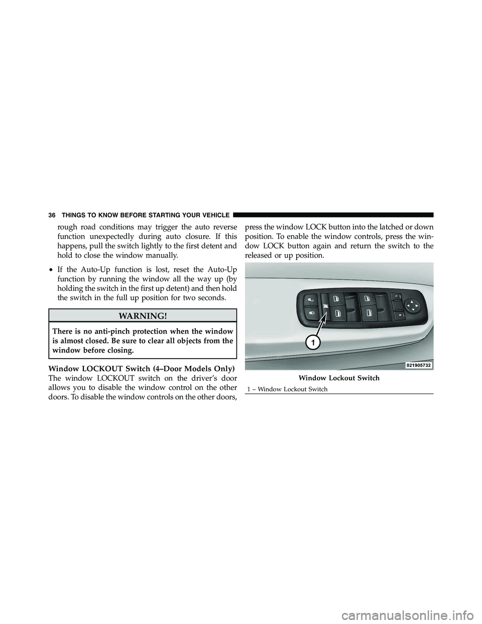
Window LOCKOUT Switch (4–Door Models Only)
The window LOCKOUT switch on the driver’s door
allows you to disable the window control on the other
doors. To disable the window controls on the other doors, press the window LOCK button into the latched or down
position. To enable the window controls, press the win-
dow LOCK button again and return the switch to the
released or up position.
Window Lockout Switch1 – Window Lockout Switch36 THINGS TO KNOW BEFORE STARTING YOUR VEHICLE
Page 109 of 472
best results, the Voice Training session should be com-
pleted when the vehicle is parked with the engine
running, all windows closed, and the blower fan
switched off.
This procedure may be repeated with a new user. The
system will adapt to the last trained voice only.
Reset
• press the button.
• After the “Ready” prompt, and the following beep, say
“Setup”, then “Reset”.
This will delete all phone pairing, phone book entries,
and other settings in all language modes. The System will
prompt you before resetting to factory settings. Voice Command
• For best performance, adjust the rearview mirror to
provide at least 1
� 2
in (1 cm) gap between the overhead
console (if equipped) and the mirror.
• Always wait for the beep before speaking.
• Speak normally, without pausing, just as you would
speak to a person sitting a few feet/meters away from
you.
• Make sure that no one other than you is speaking
during a Voice Command period.
• Performance is maximized under:
• low-to-medium blower setting,
• low-to-medium vehicle speed,
• low road noise,
• smooth road surface,108 UNDERSTANDING THE FEATURES OF YOUR VEHICLE
Page 112 of 472
Send Messages:
You can send messages using Uconnect™ Phone. To send
a new message:
• Press the button.
• After the “Ready” prompt and the following beep, say
“SMS Send” or “Send Messages.”
• You can either say the message you wish to send or say
“List Messages.” There are 20 preset messages.
To send a message, press the button while the
system is listing the message and say “Send.”
Uconnect™ Phone will prompt you to say the name or
number of the person you wish to send the message to.
List of Preset Messages:
1. Yes
2. No 3. Where are you?
4. I need more direction.
5. L O L
6. Why
7. I love you
8. Call me
9. Call me later
10. Thanks
11. See You in 15 minutes
12. Iamonmyway
13. I’ll be late
14. Are you there yet?
15. Where are we meeting? 3 UNDERSTANDING THE FEATURES OF YOUR VEHICLE 111
Page 135 of 472
Vehicles Equipped with Remote Start
On models equipped with remote start, the drivers
ventilated seat can be programmed to come on during a
remote start. Refer to “Remote Starting System — If
Equipped” in “Things to Know Before Starting Your
Vehicle” for further information.
40-20-40 Front Bench Seat — If Equipped
The seat is divided into three segments. The outboard
seat portions are each 40% of the total width of the seat.
The back of the center portion (20%) easily folds down to
provide an armrest/center storage compartment (if
equipped).
DRIVER MEMORY SEAT — IF EQUIPPED
Driver memory seats allow the driver to recall settings
for the adjustable pedals, mirrors, seats and the radio
presets using the key fob.
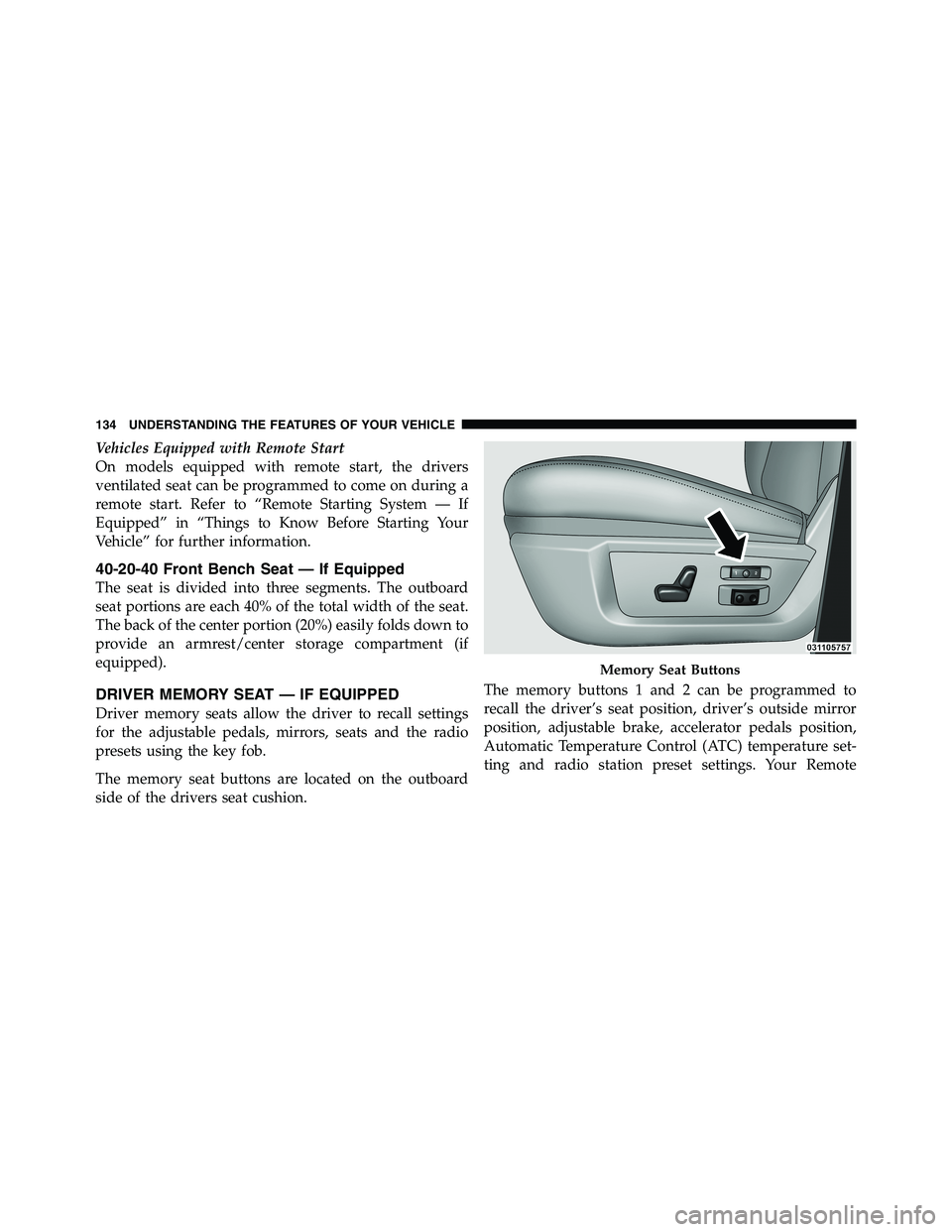
The memory seat buttons are located on the outboard
side of the drivers seat cushion. The memory buttons 1 and 2 can be programmed to
recall the driver’s seat position, driver’s outside mirror
position, adjustable brake, accelerator pedals position,
Automatic Temperature Control (ATC) temperature set-
ting and radio station preset settings. Your Remote Memory Seat Buttons134 UNDERSTANDING THE FEATURES OF YOUR VEHICLE
Page 136 of 472
Keyless Entry (RKE) transmitters can also be pro-
grammed to recall the same positions when the UN-
LOCK button is pressed.
NOTE: The power lumbar option is not programmable
with driver memory seats.
Your vehicle was delivered with two RKE transmitters.
One or both RKE transmitters can be linked to either
memory position. The memory system can accommodate
up to two RKE transmitters, each RKE transmitter linked
to either of the two memory positions.
Setting Memory Positions and Linking RKE
Transmitter to Memory
NOTE: Each time the S (SET) button and a numbered
button (1 or 2) are pressed, you erase the memory settings
for that button and store new settings.
1. Turn the vehicle key to the ON/RUN position. 2. Adjust the driver’s seat, recliner, and both sideview
mirrors to the desired positions.
NOTE: Not all motors may be moved at one time. Refer
to “Seats/Eight-Way Power Seat” in this section for
further information.
3. Adjust the brake and accelerator pedals to the desired
positions.
4. Turn on the radio and set the radio station presets (up
to 10 AM and 10 FM stations can be set).
5. Adjust the Automatic Temperature Control (ATC)
while the ATC is in Auto mode.
6. Press and release the SET button located on the
driver’s seat.
7. Within five seconds, press and release MEMORY
button 1 or 2 on the driver’s seat. The next steps must be 3 UNDERSTANDING THE FEATURES OF YOUR VEHICLE 135
Page 138 of 472
To Disable a RKE Transmitter Linked to Memory
1. Turn the ignition switch to the OFF position and
remove the key.
2. Press and release the memory SET button located on
the driver’s seat.
3. Within 10 seconds, press and release the UNLOCK
button on the RKE transmitter.
To disable another RKE transmitter linked to either
memory position, repeat Steps 1-3 for each RKE trans-
mitter.
NOTE: The capability to link RKE transmitters to
memory is enabled when delivered from the factory. The
capability to link RKE transmitters to memory can be
disabled (or later re-enabled) by an authorized dealer. For
vehicles equipped with the Electronic vehicle Informa-
tion Center (EVIC), refer to “Electronic Vehicle Informa tion Center (EVIC)/Customer-Programmable Features”
in “Understanding Your Instrument Panel” for further
information.
Self-Limiting Control
The memory system includes a self-limiting control for
full travel positioning of power seat and adjustable pedal
movement (all directions). This self-limiting control may,
however, develop an unintended movement limitation if
an obstruction is encountered sometime during usage.
One example of such an occurrence may include a box or
package obstructing the full rearward movement of the
driver’s seat. Once the obstruction is removed, the self-
limiting control may store a new maximum position. the
self-limiting control may be reset by reaching the new
stored position, then press and release MEMORY button
1 or 2. Continued seat travel beyond the new stored
position will indicate the self-limiting control has been
reset. 3 UNDERSTANDING THE FEATURES OF YOUR VEHICLE 137
Page 153 of 472
WARNING!• Persons who are unable to feel pain to the skin
because of advanced age, chronic illness, diabetes,
spinal cord injury, medication, alcohol use, ex-
haustion, or other physical conditions must exer-
cise care when using the steering wheel heater. It
may cause burns even at low temperatures, espe-
cially if used for long periods.
• Do not place anything on the steering wheel that
insulates against heat, such as a blanket or cush-
ion. This may cause the steering wheel heater to
overheat.
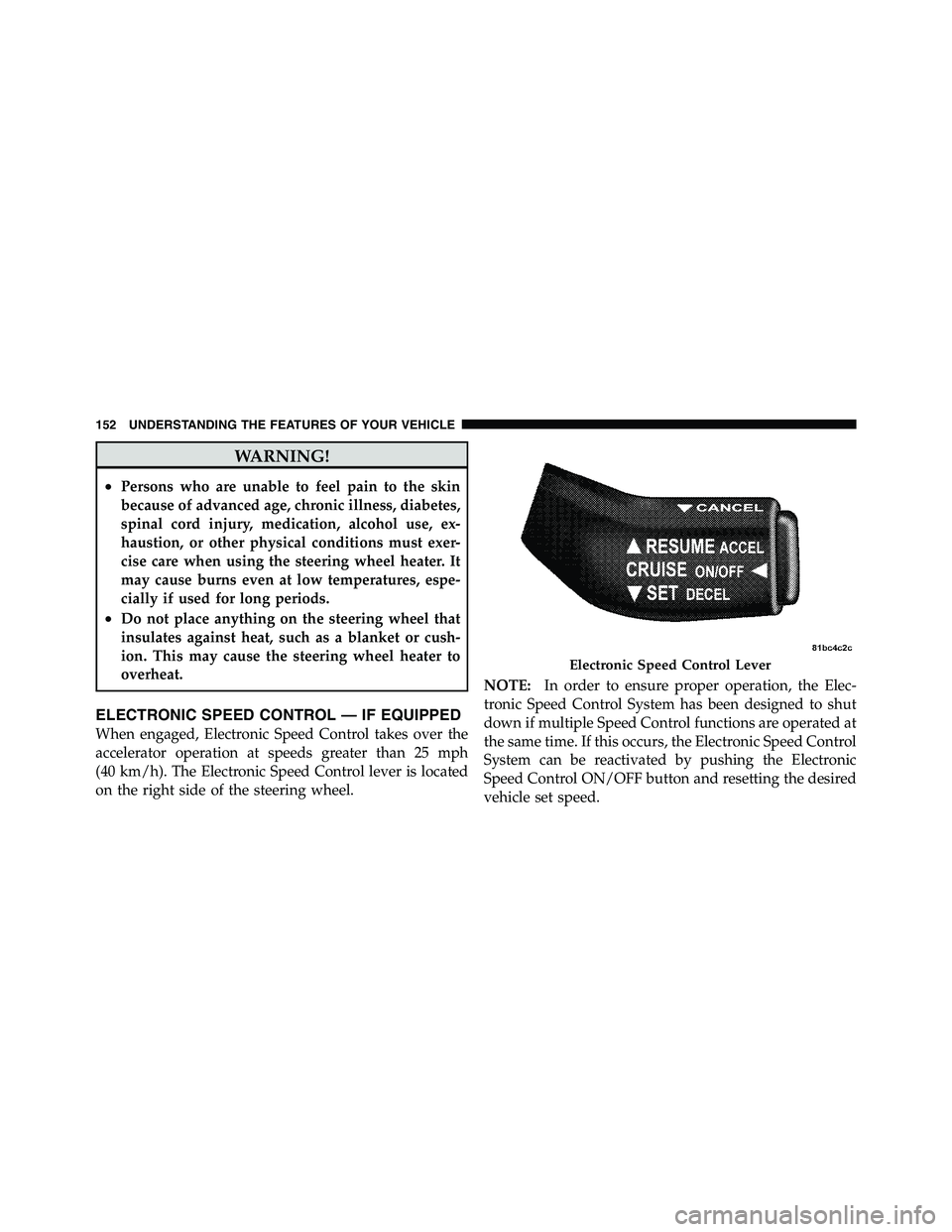
ELECTRONIC SPEED CONTROL — IF EQUIPPED
When engaged, Electronic Speed Control takes over the
accelerator operation at speeds greater than 25 mph
(40 km/h). The Electronic Speed Control lever is located
on the right side of the steering wheel. NOTE: In order to ensure proper operation, the Elec-
tronic Speed Control System has been designed to shut
down if multiple Speed Control functions are operated at
the same time. If this occurs, the Electronic Speed Control
System can be reactivated by pushing the Electronic
Speed Control ON/OFF button and resetting the desired
vehicle set speed. Electronic Speed Control Lever152 UNDERSTANDING THE FEATURES OF YOUR VEHICLE
Page 161 of 472
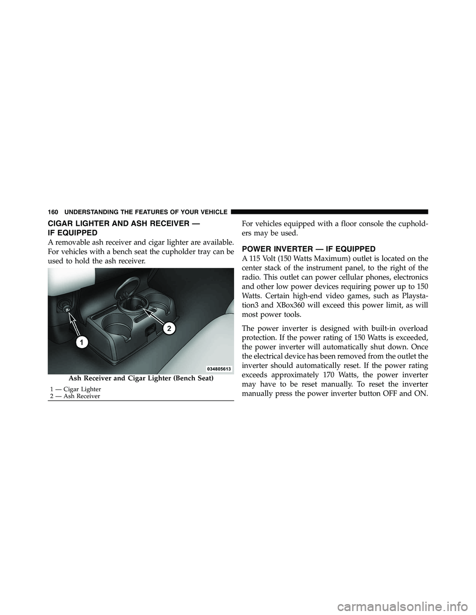
CIGAR LIGHTER AND ASH RECEIVER —
IF EQUIPPED
A removable ash receiver and cigar lighter are available.
For vehicles with a bench seat the cupholder tray can be
used to hold the ash receiver. For vehicles equipped with a floor console the cuphold-
ers may be used.
POWER INVERTER — IF EQUIPPED
A 115 Volt (150 Watts Maximum) outlet is located on the
center stack of the instrument panel, to the right of the
radio. This outlet can power cellular phones, electronics
and other low power devices requiring power up to 150
Watts. Certain high-end video games, such as Playsta-
tion3 and XBox360 will exceed this power limit, as will
most power tools.
The power inverter is designed with built-in overload
protection. If the power rating of 150 Watts is exceeded,
the power inverter will automatically shut down. Once
the electrical device has been removed from the outlet the
inverter should automatically reset. If the power rating
exceeds approximately 170 Watts, the power inverter
may have to be reset manually. To reset the inverter
manually press the power inverter button OFF and ON.Ash Receiver and Cigar Lighter (Bench Seat)1 — Cigar Lighter
2 — Ash Receiver160 UNDERSTANDING THE FEATURES OF YOUR VEHICLE
Page 183 of 472
10. TOW/HAUL
The TOW HAUL button is located on the
center stack switch bank. This light will illumi-
nate when TOW HAUL mode is selected
11. Vehicle Security Light — If Equipped
This light will flash at a fast rate for approxi-
mately 15 seconds, when the vehicle security
alarm is arming, and then will flash slowly
until the vehicle is disarmed.
12. Oil Pressure Gauge — If Equipped
The pointer should always indicate some oil pressure
when the engine is running. A continuous high or low
reading under normal driving conditions may indicate a
lubrication system malfunction. Immediate service
should be obtained from an authorized dealer. 13. Odometer/Trip Odometer Button
Press this button to toggle between the odometer and the
trip odometer display. Holding the button in resets the
trip odometer reading when in trip mode.
14. Odometer / Electronic Vehicle Information Center
(EVIC) Display Area
Odometer Display
The odometer shows the total distance the vehicle has
been driven. Regulations require that upon transfer of
vehicle ownership, the seller certify to the purchaser the
correct mileage that the vehicle has been driven. If your
odometer needs to be repaired or serviced, the repair
technician should leave the odometer reading the same
as it was before the repair or service. If s/he cannot do so,
then the odometer must be set at zero, and a sticker must
be placed in the door jamb stating what the mileage was
before the repair or service. It is a good idea for you to
make a record of the odometer reading before the repair/182 UNDERSTANDING YOUR INSTRUMENT PANEL
Page 184 of 472
service, so that you can be sure that it is properly reset, or
that the door jamb sticker is accurate if the odometer
must be reset at zero.
The two trip odometers show individual trip mileage. To
switch from odometer to trip odometers, press and
release the TRIP ODOMETER button.
To reset a trip odometer, display the desired trip odom-
eter to be reset then push and hold the button for
approximately two seconds until the display resets.
Vehicle Odometer Messages
When the appropriate conditions exist, the following
messages will display in the odometer:
noFUSE .......................... Fuse Fault
CHAngE OIL ............... Oil Change Required
LoWASH .................... LowW asher Fluid
NOTE: There is also an engine hour function. This
indicates the total number of hours the engine has been running. To display the engine hours on the base cluster,
perform the following: Place the ignition in the ON/
RUN, but do not start the engine. With the odometer
value displayed, hold the TRIP button down for a period
of six seconds. The odometer will change to trip value
first, then it will display the engine hour value. The
engine hours will be displayed for a period of 30 seconds
until the ignition is turned OFF or the engine is started.
Some of the above warnings will be displayed in the
Electronic Vehicle Information Center (EVIC) Display
Area located in the instrument cluster. Refer to ”Elec-
tronic Vehicle Information Center (EVIC) — If Equipped”
for further information.
If the vehicle diagnostic system determines
that the fuel filler cap is loose, improperly
installed, or damaged, a loose gascap indi-
cator will display in the odometer display
area. Tighten the fuel filler cap properly and
pressLoose
Gascap
Indicator
4 UNDERSTANDING YOUR INSTRUMENT PANEL 183