run flat RAM CHASSIS CAB 2011 Owners Manual
[x] Cancel search | Manufacturer: RAM, Model Year: 2011, Model line: CHASSIS CAB, Model: RAM CHASSIS CAB 2011Pages: 472, PDF Size: 7.38 MB
Page 55 of 472
Airbag Deployment Sensors and Controls
Occupant Restraint Controller (ORC)
The ORC is part of a Federally regulated safety system
required for this vehicle.
The ORC determines if deployment of the front airbags in
a frontal collision is required. Based on impact sensor
signals a central electronic ORC deploys the Advanced
Front Airbags, as required, depending on the severity
and type of impact.
Advanced Front Airbags are designed to provide addi-
tional protection by supplementing the seat belts in
certain frontal collisions depending on the severity and
type of collision. Advanced Front Airbags are not ex-
pected to reduce the risk of injury in rear, side or rollover
collisions.
The Advanced Front Airbags will not deploy in all frontal
collisions, including some that may produce substantial vehicle damage — for example, some pole collisions,
truck underrides, and angle offset collisions. On the other
hand, depending on the type and location of impact,
Advanced Front Airbags may deploy in crashes with
little vehicle front-end damage but that produce a severe
initial deceleration.
Because airbag sensors measure vehicle deceleration over
time, vehicle speed and damage by themselves are not
good indicators of whether or not an airbag should have
deployed.
Seat belts are necessary for your protection in all acci-
dents, and also are needed to help keep you in position,
away from an inflating airbag.
The ORC monitors the readiness of the electronic parts of
the airbag system whenever the ignition switch is in the
START or ON/RUN position. If the key is in the LOCK
position, in the ACC position, or not in the ignition, the
airbag system is not on and the airbags will not inflate.54 THINGS TO KNOW BEFORE STARTING YOUR VEHICLE
Page 59 of 472
Maintaining Your Airbag System
WARNING!• Modifications to any part of the airbag system
could cause it to fail when you need it. You could
be injured if the airbag system is not there to
protect you. Do not modify the components or
wiring, including adding any kind of badges or
stickers to the steering wheel hub trim cover or the
upper right side of the instrument panel. Do not
modify the front bumper, vehicle body structure,
or add aftermarket side steps or running boards.
• It is dangerous to try to repair any part of the
airbag system yourself. Be sure to tell anyone who
works on your vehicle that it has an airbag system.
(Continued) WARNING! (Continued)• Do not attempt to modify any part of your ad-
vanced airbag system. The airbag may inflate
accidentally or may not function properly if modi-
fications are made. Take your vehicle to an autho-
rized dealer for any advanced airbag system ser-
vice. If your seat, including your trim cover and
cushion, needs to be serviced in any way (includ-
ing removal or loosening/tightening of seat attach-
ment bolts), take the vehicle to your authorized
dealer. Only manufacturer approved seat accesso-
ries may be used. If it is necessary to modify the
airbag system for persons with disabilities, contact
your authorized dealer.58 THINGS TO KNOW BEFORE STARTING YOUR VEHICLE
Page 60 of 472
Airbag Warning Light
You will want to have the airbags ready to
inflate for your protection in a collision. The
Airbag Warning Light monitors the internal
circuits and interconnecting wiring associated
with airbag system electrical components. While the
airbag system is designed to be maintenance free, if any
of the following occurs, have an authorized dealer ser-
vice the airbag system immediately.
• The Airbag Warning Light does not come on during
the four to eight seconds when the ignition switch is
first turned to the ON/RUN position.
• The Airbag Warning Light remains on after the four to
eight-second interval.
• The Airbag Warning Light comes on intermittently or
remains on while driving.
NOTE: If the speedometer, tachometer, or any engine
related gauges are not working, the Occupant Restraint Controller (ORC) may also be disabled. The airbags may
not be ready to inflate for your protection. Promptly
check the fuse block for blown fuses. Refer to the label
located on the inside of the fuse block cover for the
proper airbag fuses. See your authorized dealer if the
fuse is good.
Event Data Recorder (EDR)
This vehicle is equipped with an event data recorder
(EDR). The main purpose of an EDR is to record, in
certain crash or near crash-like situations, such as an air
bag deployment or hitting a road obstacle, data that will
assist in understanding how a vehicle’s systems per-
formed. The EDR is designed to record data related to
vehicle dynamics and safety systems for a short period of
time, typically 30 seconds or less. The EDR in this vehicle
is designed to record such data as:
• How various systems in your vehicle were operating; 2 THINGS TO KNOW BEFORE STARTING YOUR VEHICLE 59
Page 283 of 472

N
Neutral - This range disengages both the front and rear
driveshafts from the powertrain. To be used for flat
towing behind another vehicle. Refer to “Recreational
Towing” in Starting and Operating” for further
information.
Shifting Procedure
NOTE:
• If any of the requirements to select a new transfer case
position have not been met, the transfer case will not
shift. The position indicator light for the previous
position will remain ON and the newly selected posi-
tion indicator light will continue to flash until all the
requirements for the selected position have been met.
To retry a shift: return the control knob back to the
original position, make certain all shift requirements
have been met, wait five seconds and try the shift
again. • If all the requirements to select a new transfer case
position have been met, the current position indicator
light will turn OFF, the selected position indicator light
will flash until the transfer case completes the shift.
When the shift is complete, the position indicator light
for the selected position will stop flashing and remain
ON.
2WD ⇔ 4WD LOCK
Rotate the 4WD control switch to the desired position.
Shifts between 2WD and 4WD LOCK can be done with
the vehicle stopped or in motion. With the vehicle in
motion, the transfer case will engage/disengage faster if
you momentarily release the accelerator pedal after turn-
ing the control switch. If the vehicle is stopped, the
ignition switch must be in the ON position with the
engine either running or off. This shift cannot be com-
pleted if the ignition switch is in the ACC position.282 STARTING AND OPERATING
Page 300 of 472

Tire Terminology and Definitions
Term Definition
B-Pillar The vehicle B-Pillar is a structural member of the body located
between the front and rear door (of a four-door vehicle) running
from the sill to the roof.
Cold Tire Pressure Cold tire inflation pressure is defined as the tire pressure after the
vehicle has not been driven for at least 3 hours, or driven less
than 1 mile (1.6 km) after sitting for a three hour period. Inflation
pressure is measured in units of PSI (pounds per square inch) or
KPa (kilopascals).
Maximum Inflation Pressure The maximum inflation pressure is the maximum permissible cold
tire inflation pressure for this tire. The max inflation pressure is
molded into the sidewall.
Recommended Inflation Pressure Vehicle manufacturer’s recommended tire inflation pressure as
shown on the tire placard.
Tire Placard A paper label permanently attached to the vehicle showing the
vehicle’s loading capacity, the original equipment tire size and the
recommended inflation pressure.
5 STARTING AND OPERATING 299
Page 309 of 472
When adjusting inflation pressure to a tire and wheel
assembly mounted on a vehicle, use a Remote Mount
Automatic Inflation Kit or see your authorized dealer.
NOTE: Never attempt to re-inflate a tire and wheel
assembly which has been run flat or is extremely under-
inflated without first removing the tire from the wheel
assembly for inspection.
Personnel trained, supervised, and equipped according
to Federal Occupational Safety and Health Administra-
tion (OSHA) should perform this work.
Inflation Pressure Adjustment When Not Mounted to
Vehicle
When adjusting inflation pressure to a tire and wheel
assembly not mounted on a vehicle, use a Remote Mount
Automatic Inflation Kit and a Tire Inflation Cage or see
your authorized dealer. Tire Pressures for High Speed Operation
The manufacturer advocates driving at safe speeds
within posted speed limits. Where speed limits or condi-
tions are such that the vehicle can be driven at high
speeds, maintaining correct tire inflation pressure is very
important. Increased tire pressure and reduced vehicle
loading may be required for high-speed vehicle opera-
tion. Refer to original equipment or an authorized tire
dealer for recommended safe operating speeds, loading
and cold tire inflation pressures.
WARNING!High speed driving with your vehicle under maxi-
mum load is dangerous. The added strain on your
tires could cause them to fail. You could have a
serious accident resulting in serious injury or death.
Don’t drive a vehicle loaded to the maximum capac-
ity at continuous speeds above 75 mph (120 km/h).308 STARTING AND OPERATING
Page 360 of 472
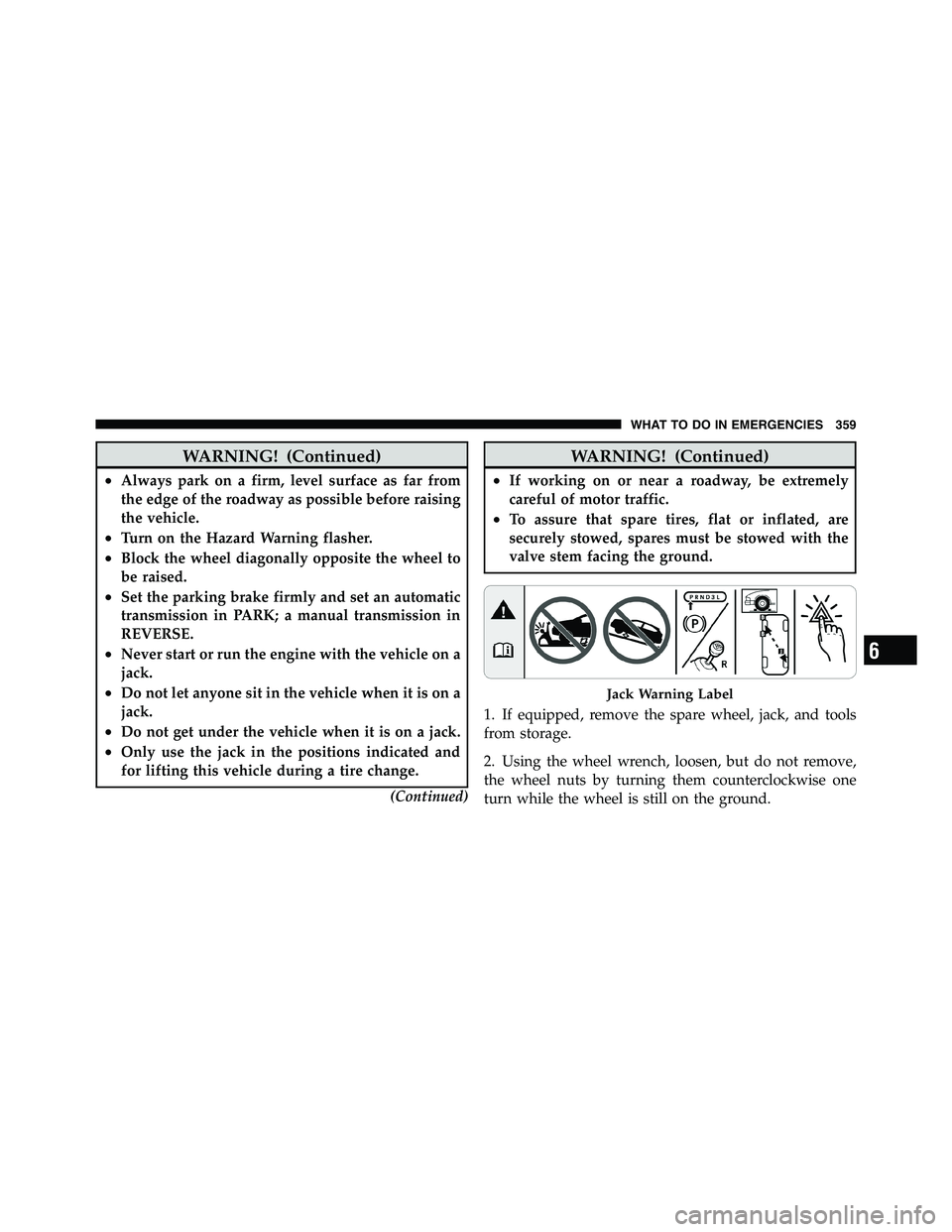
WARNING! (Continued)• Always park on a firm, level surface as far from
the edge of the roadway as possible before raising
the vehicle.
• Turn on the Hazard Warning flasher.
• Block the wheel diagonally opposite the wheel to
be raised.
• Set the parking brake firmly and set an automatic
transmission in PARK; a manual transmission in
REVERSE.
• Never start or run the engine with the vehicle on a
jack.
• Do not let anyone sit in the vehicle when it is on a
jack.
• Do not get under the vehicle when it is on a jack.
• Only use the jack in the positions indicated and
for lifting this vehicle during a tire change.
(Continued) WARNING! (Continued)• If working on or near a roadway, be extremely
careful of motor traffic.
• To assure that spare tires, flat or inflated, are
securely stowed, spares must be stowed with the
valve stem facing the ground.
1. If equipped, remove the spare wheel, jack, and tools
from storage.
2. Using the wheel wrench, loosen, but do not remove,
the wheel nuts by turning them counterclockwise one
turn while the wheel is still on the ground. Jack Warning Label
6 WHAT TO DO IN EMERGENCIES 359