buttons RAM CHASSIS CAB 2020 Owner's Manual
[x] Cancel search | Manufacturer: RAM, Model Year: 2020, Model line: CHASSIS CAB, Model: RAM CHASSIS CAB 2020Pages: 516, PDF Size: 16.57 MB
Page 232 of 516
230STARTING AND OPERATING
SPEED CONTROL
When engaged, the Speed Control takes over
accelerator operations at speeds greater than
20 mph (32 km/h) for gasoline engines and
25 mph (40 km/h) for diesel engines.
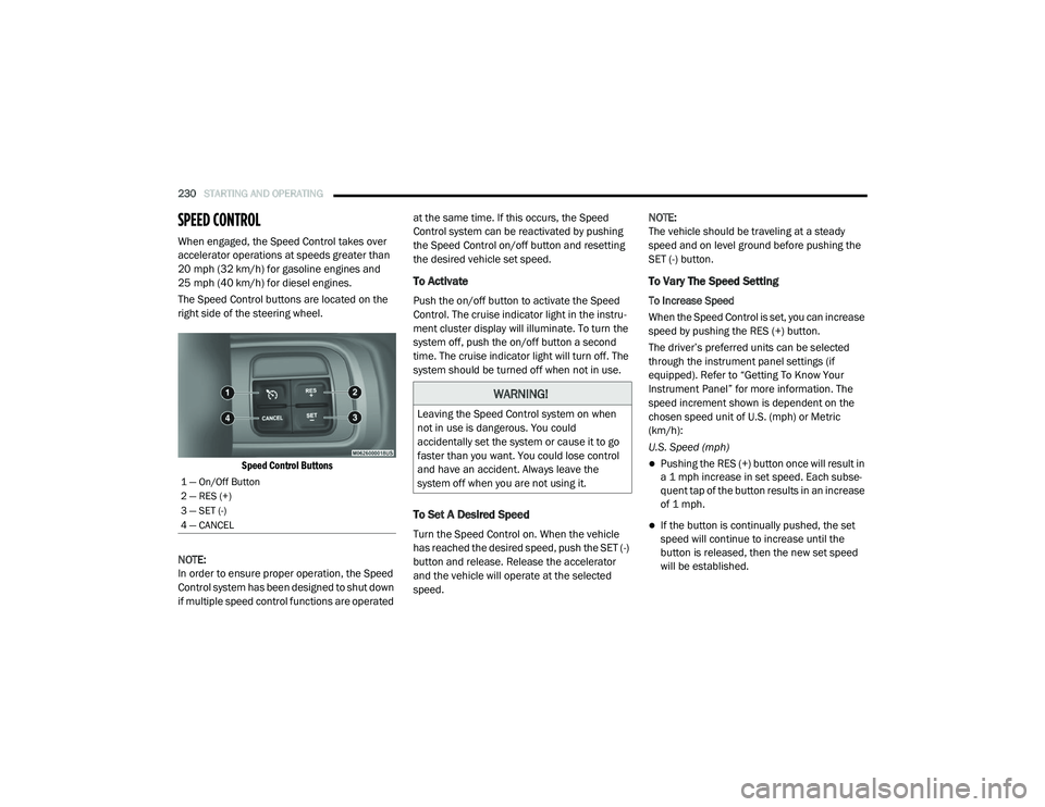
The Speed Control buttons are located on the
right side of the steering wheel.
Speed Control Buttons
NOTE:
In order to ensure proper operation, the Speed
Control system has been designed to shut down
if multiple speed control functions are operated at the same time. If this occurs, the Speed
Control system can be reactivated by pushing
the Speed Control on/off button and resetting
the desired vehicle set speed.
To Activate
Push the on/off button to activate the Speed
Control. The cruise indicator light in the instru
-
ment cluster display will illuminate. To turn the
system off, push the on/off button a second
time. The cruise indicator light will turn off. The
system should be turned off when not in use.
To Set A Desired Speed
Turn the Speed Control on. When the vehicle
has reached the desired speed, push the SET (-)
button and release. Release the accelerator
and the vehicle will operate at the selected
speed. NOTE:
The vehicle should be traveling at a steady
speed and on level ground before pushing the
SET (-) button.
To Vary The Speed Setting
To Increase Speed
When the Speed Control is set, you can increase
speed by pushing the RES (+) button.
The driver’s preferred units can be selected
through the instrument panel settings (if
equipped). Refer to “Getting To Know Your
Instrument Panel” for more information. The
speed increment shown is dependent on the
chosen speed unit of U.S. (mph) or Metric
(km/h):
U.S. Speed (mph)
Pushing the RES (+) button once will result in
a 1 mph increase in set speed. Each subse -
quent tap of the button results in an increase
of 1 mph.
If the button is continually pushed, the set
speed will continue to increase until the
button is released, then the new set speed
will be established.
1 — On/Off Button
2 — RES (+)
3 — SET (-)
4 — CANCEL
WARNING!
Leaving the Speed Control system on when
not in use is dangerous. You could
accidentally set the system or cause it to go
faster than you want. You could lose control
and have an accident. Always leave the
system off when you are not using it.
2020_RAM_CHASSIS_CAB_OM_USA=GUID-6C67832B-7839-4CCF-BEFC-CDF988F949EA=1=en=.book Page 230
Page 234 of 516
232STARTING AND OPERATING
(Continued)
ADAPTIVE CRUISE CONTROL (ACC) — IF
EQUIPPED
Adaptive Cruise Control (ACC) increases the
driving convenience provided by cruise control
while traveling on highways and major road-
ways. However, it is not a safety system and not
designed to prevent collisions. Speed Control
function performs differently. Please refer to
the proper section within this chapter.
ACC will allow you to keep cruise control
engaged in light to moderate traffic conditions
without the constant need to reset your cruise
control. ACC utilizes a radar sensor and a
forward facing camera designed to detect a
vehicle directly ahead of you.
NOTE:
If the sensor does not detect a vehicle ahead
of you, ACC will maintain a fixed set speed.
If the ACC sensor detects a vehicle ahead,
ACC will apply limited braking or accelerate
(not to exceed the original set speed) auto -
matically to maintain a preset following
distance, while matching the speed of the
vehicle ahead. The Cruise Control system has two control
modes:
Adaptive Cruise Control mode for main
-
taining an appropriate distance between
vehicles.
Normal (Fixed Speed) Cruise Control mode
for cruising at a constant preset speed. For
additional information, refer to “Normal
(Fixed Speed) Cruise Control Mode” in this
section.
NOTE:
Normal (Fixed Speed) Cruise Control will not
react to preceding vehicles. Always be aware of
the mode selected.
You can change the mode by using the Cruise
Control buttons. The two control modes func -
tion differently. Always confirm which mode is
selected.
WARNING!
Adaptive Cruise Control (ACC) is a conve -
nience system. It is not a substitute for
active driving involvement. It is always the
driver’s responsibility to be attentive of
road, traffic, and weather conditions,
vehicle speed, distance to the vehicle
ahead; and, most importantly, brake opera -
tion to ensure safe operation of the vehicle
under all road conditions. Your complete
attention is always required while driving to
maintain safe control of your vehicle.
Failure to follow these warnings can result
in a collision and death or serious personal
injury.
The ACC system:
Does not react to pedestrians,
oncoming vehicles, and stationary
objects (e.g., a stopped vehicle in a
traffic jam or a disabled vehicle).
Cannot take street, traffic, and weather conditions into account, and may be
limited upon adverse sight distance
conditions.
2020_RAM_CHASSIS_CAB_OM_USA=GUID-6C67832B-7839-4CCF-BEFC-CDF988F949EA=1=en=.book Page 232
Page 235 of 516
STARTING AND OPERATING233
(Continued)
Adaptive Cruise Control (ACC) Operation
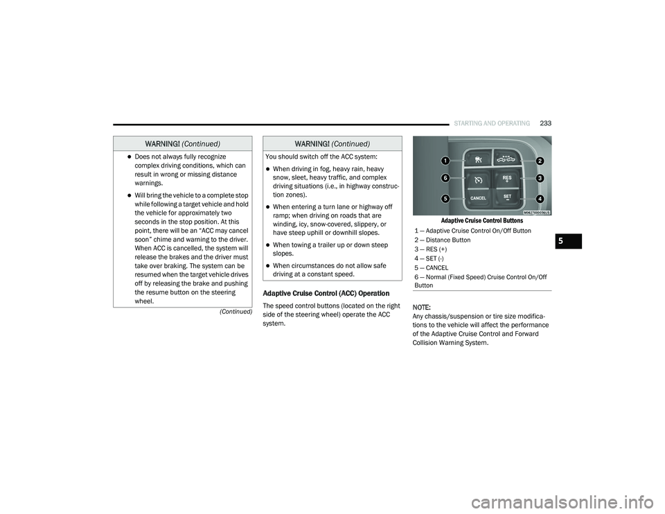
The speed control buttons (located on the right
side of the steering wheel) operate the ACC
system.
Adaptive Cruise Control Buttons
NOTE:
Any chassis/suspension or tire size modifica -
tions to the vehicle will affect the performance
of the Adaptive Cruise Control and Forward
Collision Warning System.
Does not always fully recognize complex driving conditions, which can
result in wrong or missing distance
warnings.
Will bring the vehicle to a complete stop while following a target vehicle and hold
the vehicle for approximately two
seconds in the stop position. At this
point, there will be an “ACC may cancel
soon” chime and warning to the driver.
When ACC is cancelled, the system will
release the brakes and the driver must
take over braking. The system can be
resumed when the target vehicle drives
off by releasing the brake and pushing
the resume button on the steering
wheel.
WARNING! (Continued)
You should switch off the ACC system:
When driving in fog, heavy rain, heavy
snow, sleet, heavy traffic, and complex
driving situations (i.e., in highway construc -
tion zones).
When entering a turn lane or highway off
ramp; when driving on roads that are
winding, icy, snow-covered, slippery, or
have steep uphill or downhill slopes.
When towing a trailer up or down steep
slopes.
When circumstances do not allow safe
driving at a constant speed.
WARNING! (Continued)
1 — Adaptive Cruise Control On/Off Button
2 — Distance Button
3 — RES (+)
4 — SET (-)
5 — CANCEL
6 — Normal (Fixed Speed) Cruise Control On/Off
Button
5
2020_RAM_CHASSIS_CAB_OM_USA=GUID-6C67832B-7839-4CCF-BEFC-CDF988F949EA=1=en=.book Page 233
Page 263 of 516
STARTING AND OPERATING261
AUX Camera — If Equipped
Your vehicle may be equipped with one or two
AUX Cameras, which display a rearview image
from the trailer on the touchscreen.
Activation
The AUX Camera is activated by first pressing
the Backup Camera, Cargo Camera (if
equipped), or Surround View Camera (if
equipped) button on the touchscreen, followed
by the AUX button located in the upper left
corner of the rearview display. The AUX camera
can also be activated when the vehicle is in
REVERSE by pressing the AUX button.
If equipped with two AUX Cameras, you can
switch between each camera by then pressing
the AUX1 or AUX2 buttons on the Trailer Camera
display.
AUX1 Camera Button
AUX2 Camera Button Deactivation
The AUX Camera is deactivated by pressing the
“X” in the upper right corner of the touchscreen.
This will return the display back to the previ
-
ously displayed screen.
NOTE:
If the AUX button is pressed and no AUX
Camera is connected, the touchscreen will
display a blue screen along with the message
“Camera System Unavailable.” The screen
can be exited out by pressing the “X” in the
upper right hand corner. This will return the
display back to the previously displayed
screen.
Zoom View is not available with the AUX
Camera feature.
The display will always default to the Trailer
Camera display (AUX 1).
SURROUND VIEW CAMERA SYSTEM — IF
EQUIPPED
Your vehicle may be equipped with the
Surround View Camera System that allows you
to see an on-screen image of the surroundings
and top view of your vehicle whenever the gear
selector is put into REVERSE or manually acti -
vated via the Uconnect system. The top view of
the vehicle will show which doors are open. The
image will be displayed on the touchscreen
display along with a caution note “Check Entire
Surroundings” across the top of the screen.
After five seconds, this note will disappear. The
Surround View Camera System is comprised of
three sequential cameras located in the front
grille and side mirrors, in addition to a fourth
Rear Back Up Camera.
5
2020_RAM_CHASSIS_CAB_OM_USA=GUID-6C67832B-7839-4CCF-BEFC-CDF988F949EA=1=en=.book Page 261
Page 269 of 516
STARTING AND OPERATING267
AUX Camera — If Equipped
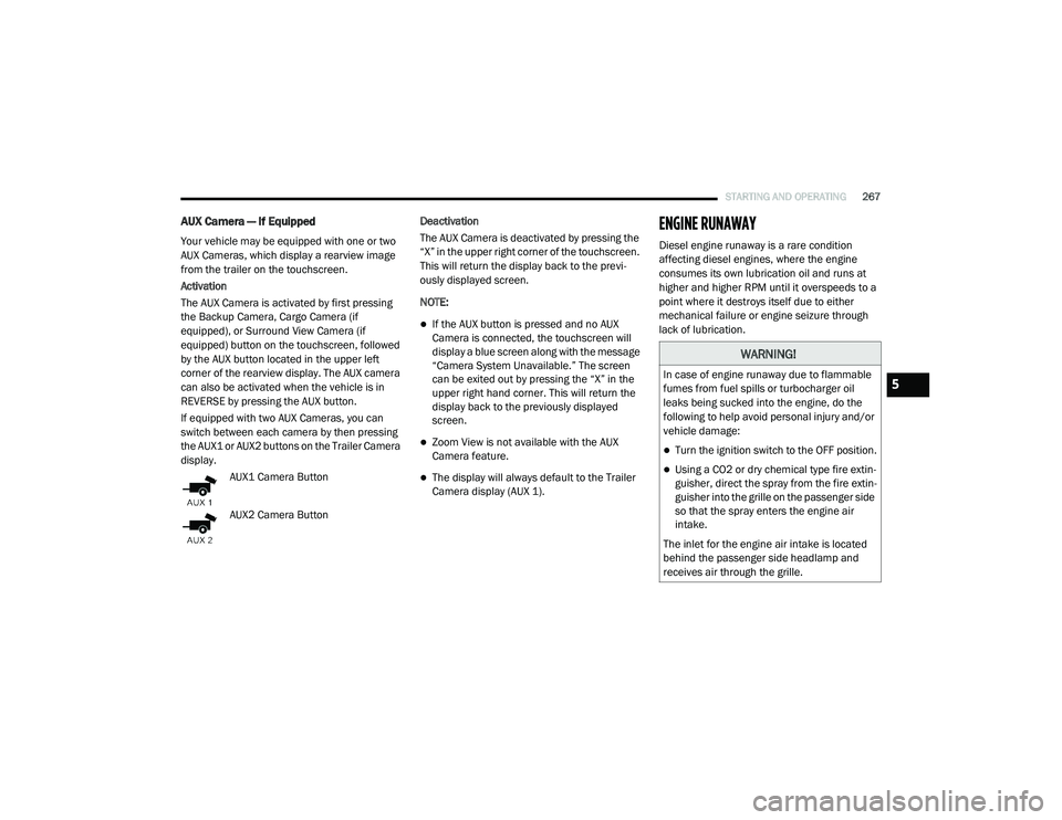
Your vehicle may be equipped with one or two
AUX Cameras, which display a rearview image
from the trailer on the touchscreen.
Activation
The AUX Camera is activated by first pressing
the Backup Camera, Cargo Camera (if
equipped), or Surround View Camera (if
equipped) button on the touchscreen, followed
by the AUX button located in the upper left
corner of the rearview display. The AUX camera
can also be activated when the vehicle is in
REVERSE by pressing the AUX button.
If equipped with two AUX Cameras, you can
switch between each camera by then pressing
the AUX1 or AUX2 buttons on the Trailer Camera
display.
AUX1 Camera Button
AUX2 Camera Button Deactivation
The AUX Camera is deactivated by pressing the
“X” in the upper right corner of the touchscreen.
This will return the display back to the previ
-
ously displayed screen.
NOTE:
If the AUX button is pressed and no AUX
Camera is connected, the touchscreen will
display a blue screen along with the message
“Camera System Unavailable.” The screen
can be exited out by pressing the “X” in the
upper right hand corner. This will return the
display back to the previously displayed
screen.
Zoom View is not available with the AUX
Camera feature.
The display will always default to the Trailer
Camera display (AUX 1).
ENGINE RUNAWAY
Diesel engine runaway is a rare condition
affecting diesel engines, where the engine
consumes its own lubrication oil and runs at
higher and higher RPM until it overspeeds to a
point where it destroys itself due to either
mechanical failure or engine seizure through
lack of lubrication.
WARNING!
In case of engine runaway due to flammable
fumes from fuel spills or turbocharger oil
leaks being sucked into the engine, do the
following to help avoid personal injury and/or
vehicle damage:
Turn the ignition switch to the OFF position.
Using a CO2 or dry chemical type fire extin -
guisher, direct the spray from the fire extin -
guisher into the grille on the passenger side
so that the spray enters the engine air
intake.
The inlet for the engine air intake is located
behind the passenger side headlamp and
receives air through the grille.
5
2020_RAM_CHASSIS_CAB_OM_USA=GUID-6C67832B-7839-4CCF-BEFC-CDF988F949EA=1=en=.book Page 267
Page 284 of 516
282STARTING AND OPERATING
The trailer and the vehicle’s stop lamps will
come on when braking normally with the vehicle
brake pedal. Only the trailer stop lamps will
come on when the manual brake control lever is
applied.
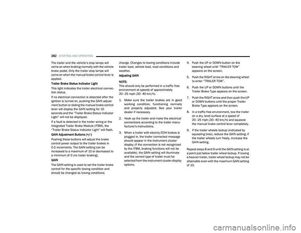
Trailer Brake Status Indicator Light
This light indicates the trailer electrical connec -
tion status.
If no electrical connection is detected after the
ignition is turned on, pushing the GAIN adjust -
ment button or sliding the manual brake control
lever will display the GAIN setting for 10
seconds and the “Trailer Brake Status Indicator
Light” will not be displayed.
If a fault is detected in the trailer wiring or the
Integrated Trailer Brake Module (ITBM), the
“Trailer Brake Status Indicator Light” will flash.
GAIN Adjustment Buttons (+/-)
Pushing these buttons will adjust the brake
control power output to the trailer brakes in
0.5 increments. The GAIN setting can be
increased to a maximum of 10 or decreased to
a minimum of 0 (no trailer braking).
GAIN
The GAIN setting is used to set the trailer brake
control for the specific towing condition and
should be changed as towing conditions change. Changes to towing conditions include
trailer load, vehicle load, road conditions and
weather.
Adjusting GAIN
NOTE:
This should only be performed in a traffic free
environment at speeds of approximately
20–25 mph (30–40 km/h).
1. Make sure the trailer brakes are in good
working condition, functioning normally
and properly adjusted. See your trailer
dealer if necessary.
2. Hook up the trailer and make the electrical connections according to the trailer manu -
facturer's instructions.
3. When a trailer with electric/EOH brakes is plugged in, the trailer connected message
should appear in the instrument cluster
display (if the connection is not recognized
by the ITBM, braking functions will not be
available), the GAIN setting will illuminate
and the correct type of trailer must be
selected from the instrument cluster display
options. 4. Push the UP or DOWN button on the
steering wheel until “TRAILER TOW”
appears on the screen.
5. Push the RIGHT arrow on the steering wheel to enter “TRAILER TOW”.
6. Push the UP or DOWN buttons until the Trailer Brake Type appears on the screen.
7. Push the RIGHT arrow and then push the UP or DOWN buttons until the proper Trailer
Brake Type appears on the screen.
8. In a traffic-free environment, tow the trailer on a dry, level surface at a speed of
20–25 mph (30–40 km/h) and squeeze
the manual brake control lever completely.
9. If the trailer wheels lockup (indicated by squealing tires), reduce the GAIN setting; if
the trailer wheels turn freely, increase the
GAIN setting.
Repeat steps 8 and 9 until the GAIN setting is at
a point just below trailer wheel lockup. If towing
a heavier trailer, trailer wheel lockup may not be
attainable even with the maximum GAIN setting
of 10.
2020_RAM_CHASSIS_CAB_OM_USA=GUID-6C67832B-7839-4CCF-BEFC-CDF988F949EA=1=en=.book Page 282
Page 296 of 516
294
IN CASE OF EMERGENCY
HAZARD WARNING FLASHERS
The Hazard Warning Flashers switch
is located on the upper switch bank
just below the radio.
NOTE:
If your vehicle is equipped with a 12–inch
Uconnect display, the Hazard Warning switch is
located above the display.
Push the switch to turn on the Hazard Warning
flashers. When the switch is activated, all direc -
tional turn signals will flash on and off to warn
oncoming traffic of an emergency. Push the
switch a second time to turn off the Hazard
Warning flashers. This is an emergency warning system and it
should not be used when the vehicle is in
motion. Use it when your vehicle is disabled and
it is creating a safety hazard for other motorists.
When you must leave the vehicle to seek assis
-
tance, the Hazard Warning flashers will
continue to operate even though the ignition is
placed in the OFF position.
NOTE:
With extended use the Hazard Warning flashers
may wear down your battery.
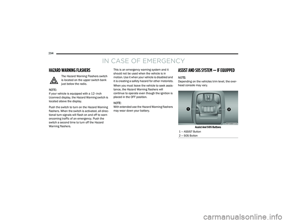
ASSIST AND SOS SYSTEM — IF EQUIPPED
NOTE:
Depending on the vehicles trim level, the over -
head console may vary.
Assist And SOS Buttons
1 — ASSIST Button
2 — SOS Button
2020_RAM_CHASSIS_CAB_OM_USA=GUID-6C67832B-7839-4CCF-BEFC-CDF988F949EA=1=en=.book Page 294
Page 297 of 516
IN CASE OF EMERGENCY295
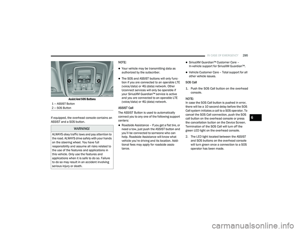
Assist And SOS Buttons
If equipped, the overhead console contains an
ASSIST and a SOS button. NOTE:
Your vehicle may be transmitting data as
authorized by the subscriber.
The SOS and ASSIST buttons will only func
-
tion if you are connected to an operable LTE
(voice/data) or 4G (data) network. Other
Uconnect services will only be operable if
your SiriusXM Guardian™ service is active
and you are connected to an operable LTE
(voice/data) or 4G (data) network.
ASSIST Call
The ASSIST Button is used to automatically
connect you to any one of the following support
centers:
Roadside Assistance – If you get a flat tire, or
need a tow, just push the ASSIST button and
you’ll be connected to someone who can
help. Roadside Assistance will know what
vehicle you’re driving and its location. Addi -
tional fees may apply for roadside assis -
tance.
SiriusXM Guardian™ Customer Care –
In-vehicle support for SiriusXM Guardian™.
Vehicle Customer Care – Total support for all
other vehicle issues.
SOS Call
1. Push the SOS Call button on the overhead console.
NOTE:
In case the SOS Call button is pushed in error,
there will be a 10 second delay before the SOS
Call system initiates a call to a SOS operator. To
cancel the SOS Call connection, push the SOS
call button on the overhead console or press
the cancellation button on the Device Screen.
Termination of the SOS Call will turn off the
green LED light on the overhead console.
2. The LED light located between the ASSIST and SOS buttons on the overhead console
will turn green once a connection to a SOS
operator has been made.
1 — ASSIST Button
2 — SOS Button
WARNING!
ALWAYS obey traffic laws and pay attention to
the road. ALWAYS drive safely with your hands
on the steering wheel. You have full
responsibility and assume all risks related to
the use of the features and applications in
this vehicle. Only use the features and
applications when it is safe to do so. Failure
to do so may result in an accident involving
serious injury or death.
6
2020_RAM_CHASSIS_CAB_OM_USA=GUID-6C67832B-7839-4CCF-BEFC-CDF988F949EA=1=en=.book Page 295
Page 299 of 516
IN CASE OF EMERGENCY297
SOS Call System Limitations
Vehicles sold in Mexico DO NOT have SOS Call
system capabilities.
SOS or other emergency line operators in
Mexico may not answer or respond to SOS
system calls.
If the SOS Call system detects a malfunction,
any of the following may occur at the time the
malfunction is detected, and at the beginning of
each ignition cycle:
The overhead console light located between
the ASSIST and SOS buttons will continuously
be illuminated red.
The Device Screen will display the following
message: “Vehicle device requires service.
Please contact an authorized dealer.”
An In-Vehicle Audio message will state
“Vehicle device requires service. Please
contact an authorized dealer.” Even if the SOS Call system is fully functional,
factors beyond FCA US LLC’s control may
prevent or stop the SOS Call system operation.
The SOS Call system is embedded into the
vehicle’s electrical system. Do not add
aftermarket electrical equipment to the
vehicle’s electrical system. This may
prevent your vehicle from sending a signal
to initiate an emergency call. To avoid inter
-
ference that can cause the SOS Call system
to fail, never add aftermarket equipment
(e.g., two-way mobile radio, CB radio, data
recorder, etc.) to your vehicle’s electrical
system or modify the antennas on your
vehicle. IF YOUR VEHICLE LOSES BATTERY
POWER FOR ANY REASON (INCLUDING
DURING OR AFTER AN ACCIDENT), THE
UCONNECT FEATURES, APPS AND
SERVICES, AMONG OTHERS, WILL NOT
OPERATE.
Modifications to any part of the SOS Call
system could cause the air bag system to
fail when you need it. You could be injured
if the air bag system is not there to help
protect you.
WARNING! (Continued)WARNING!
Ignoring the overhead console light could
mean you will not have SOS Call services. If
the overhead console light is illuminated,
have an authorized dealer service the SOS
Call system immediately.
The Occupant Restraint Control module
turns on the air bag Warning Light on the
instrument panel if a malfunction in any
part of the system is detected. If the Air Bag
Warning Light is illuminated, have an
authorized dealer service the Occupant
Restraint Control system immediately.
6
2020_RAM_CHASSIS_CAB_OM_USA=GUID-6C67832B-7839-4CCF-BEFC-CDF988F949EA=1=en=.book Page 297
Page 417 of 516
MULTIMEDIA415
NOTE:
FCA US LLC or your dealer may contact you
directly regarding software updates.
To help further improve vehicle security and
minimize the potential risk of a security
breach, vehicle owners should:
Routinely check www.driveuconnect.com
(US Residents) or www.driveuconnect.ca
(Canadian Residents) to learn about
available Uconnect software updates.
Only connect and use trusted media devices (e.g. personal mobile phones,
USBs, CDs).
Privacy of any wireless and wired communica -
tions cannot be assured. Third parties may
unlawfully intercept information and private
communications without your consent. For
further information, refer to “Data Collection &
Privacy” in your Uconnect Owner’s Manual
Supplement or “Onboard Diagnostic System
(OBD II) Cybersecurity” in “Getting To Know Your
Instrument Panel”.
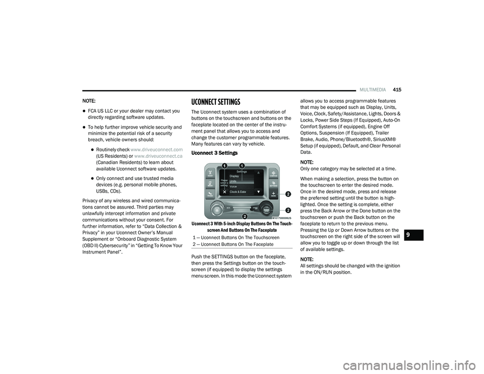
UCONNECT SETTINGS
The Uconnect system uses a combination of
buttons on the touchscreen and buttons on the
faceplate located on the center of the instru -
ment panel that allows you to access and
change the customer programmable features.
Many features can vary by vehicle.
Uconnect 3 Settings
Uconnect 3 With 5-inch Display Buttons On The Touch -
screen And Buttons On The Faceplate
Push the SETTINGS button on the faceplate,
then press the Settings button on the touch -
screen (if equipped) to display the settings
menu screen. In this mode the Uconnect system allows you to access programmable features
that may be equipped such as Display, Units,
Voice, Clock, Safety/Assistance, Lights, Doors &
Locks, Power Side Steps (If Equipped), Auto-On
Comfort Systems (if equipped), Engine Off
Options, Suspension (If Equipped), Trailer
Brake, Audio, Phone/Bluetooth®, SiriusXM®
Setup (if equipped), Default, and Clear Personal
Data.
NOTE:
Only one category may be selected at a time.
When making a selection, press the button on
the touchscreen to enter the desired mode.
Once in the desired mode, press and release
the preferred setting until the button is high
-
lighted. Once the setting is complete, either
press the Back Arrow or the Done button on the
touchscreen or push the Back button on the
faceplate to return to the previous menu.
Pressing the Up or Down Arrow buttons on the
touchscreen on the right side of the screen will
allow you to toggle up or down through the list
of available settings.
NOTE:
All settings should be changed with the ignition
in the ON/RUN position.
1 — Uconnect Buttons On The Touchscreen
2 — Uconnect Buttons On The Faceplate9
2020_RAM_CHASSIS_CAB_OM_USA=GUID-6C67832B-7839-4CCF-BEFC-CDF988F949EA=1=en=.book Page 415