air filter RAM CHASSIS CAB 2020 Owners Manual
[x] Cancel search | Manufacturer: RAM, Model Year: 2020, Model line: CHASSIS CAB, Model: RAM CHASSIS CAB 2020Pages: 516, PDF Size: 16.57 MB
Page 6 of 516

4
ONBOARD DIAGNOSTIC SYSTEM — OBD II ....... 118
Onboard Diagnostic System (OBD II)
Cybersecurity..............................................118
EMISSIONS INSPECTION AND MAINTENANCE
PROGRAMS ...................................................... 119
SAFETY
SAFETY FEATURES ............................................ 120
Anti-Lock Brake System (ABS) ................. 120
Electronic Brake Control (EBC) System ...121
AUXILIARY DRIVING SYSTEMS ........................ 129
Forward Collision Warning (FCW) With
Mitigation — If Equipped............................129 Tire Pressure Monitoring System
(TPMS) .....................................................132
OCCUPANT RESTRAINT SYSTEMS .................. 141
Occupant Restraint Systems Features ....141
Important Safety Precautions ...................141Seat Belt Systems ..................................... 142Supplemental Restraint Systems (SRS) ...151Child Restraints ........................................160
Transporting Pets ....................................179
SAFETY TIPS .................................................... 180
Transporting Passengers ..........................180
Exhaust Gas ........................................... 180
Safety Checks You Should Make Inside
The Vehicle ................................................180 Periodic Safety Checks You Should Make
Outside The Vehicle ...................................182
STARTING AND OPERATING
STARTING THE ENGINE — GAS ENGINE .........183
Automatic Transmission............................ 183
Tip Start Feature ....................................... 183Keyless Enter-N-Go — Ignition ................... 184
Normal Starting Using ENGINE START/
STOP Button ............................................ 184 Cold Weather Operation
(Below –22°F Or −30°C) ......................... 187 After Starting .............................................. 187
STARTING THE ENGINE — DIESEL ENGINE .... 187
Automatic Transmission............................ 187
Keyless Enter-N-Go — Ignition ................... 188
Extreme Cold Weather .............................. 190
Normal Starting Procedure — Engine Manifold
Air Temperature Above 66°F (19°C) ....... 191 Starting Procedure — Engine Manifold Air
Temperature 0°F To 66°F
(–18°C to 19°C) ....................................... 191 Starting Procedure — Engine Manifold Air
Temperature Below 0°F (-18°C) .............. 192 Starting Fluids ............................................ 193 NORMAL OPERATION — DIESEL ENGINE ....... 194
Cold Weather Precautions ........................ 194
Engine Idling ............................................. 197
Noise .......................................................... 198
Stopping The Engine ................................. 198Idle Shutdown ............................................ 199
Programmable Maximum Vehicle Speed ..... 199
Operating Precautions .............................. 200
Cooling System Tips .................................. 200
Diesel Particulate Filter (DPF) Manual
Regeneration - If Equipped ....................... 201
ENGINE BLOCK HEATER — IF EQUIPPED ........ 201
ENGINE BREAK-IN RECOMMENDATIONS —
GAS ENGINE ...................................................... 202
ENGINE BREAK-IN RECOMMENDATIONS —
DIESEL ENGINE .................................................. 202
DIESEL EXHAUST BRAKE
(ENGINE BRAKING) ........................................... 203
PARKING BRAKE .............................................. 204
AUTOMATIC TRANSMISSION ........................... 205 Ignition Park Interlock ............................... 206Brake/Transmission Shift Interlock
System ....................................................... 206 Six–Speed Automatic Transmission —
If Equipped ................................................ 207 Eight-Speed Automatic Transmission —
If Equipped ................................................. 213
AUXILIARY SWITCHES — IF EQUIPPED ........... 218
2020_RAM_CHASSIS_CAB_OM_USA=GUID-6C67832B-7839-4CCF-BEFC-CDF988F949EA=1=en=.book Page 4
Page 9 of 516

7
SERVICING AND MAINTENANCE
SCHEDULED SERVICING — GAS ENGINE ....... 329Maintenance Plan......................................330
Heavy Duty Use Of The Vehicle ................. 333
SCHEDULED SERVICING — DIESEL ENGINE .. 334
Oil Change Indicator System —
Cummins Diesel .........................................335 Perform Service Indicator —
Cummins Diesel ........................................335 Maintenance Plan — Cummins
Diesel Engine ............................................336
ENGINE COMPARTMENT ................................ 343
6.4L Engine ...............................................3436.7L Engine ................................................344
Checking Oil Level — Gas Engine .............345
Checking Oil Level — Diesel Engine ..........345
Adding Washer Fluid ................................345Maintenance-Free Battery .......................346
Pressure Washing ......................................346
DEALER SERVICE .............................................. 347
Engine Oil .................................................. 347Engine Oil Filter ........................................349
Engine Air Cleaner Filter .........................349
Air Conditioner Maintenance ................. 351
Accessory Drive Belt Inspection................354Draining Fuel/Water Separator Filter .....354
Engine Mounted Fuel Filter
Replacement ..............................................356 Underbody Mounted Fuel Filter
Replacement ..............................................357 Priming If The Engine Has Run
Out Of Fuel ................................................ 358 Intervention Regeneration Strategy —
Message Process Flow ............................. 359 Diesel Exhaust Fluid .................................. 359Body Lubrication ...................................... 360
Windshield Wiper Blades ........................ 360
Exhaust System ........................................ 362
Cooling System ......................................... 363
Charge Air Cooler — Inter-Cooler .............. 366
Brake System ............................................ 367Automatic Transmission............................ 368
Rear Axle And 4x4 Front Driving Axle Fluid
Level ....................................................... 370 Transfer Case ............................................ 371Noise Control System Required
Maintenance & Warranty ......................... 371
HOISTING ............................................................374
TIRES....................................................................374
Tire Safety Information ........................... 374
Tires — General Information .................... 382
Tire Types ................................................... 386
Spare Tires — If Equipped ....................... 387
Wheel And Wheel Trim Care .................. 389Tire Chains and Traction Devices ............ 390
Tire Rotation Recommendations .............. 391 DEPARTMENT OF TRANSPORTATION UNIFORM
TIRE QUALITY GRADES .................................... 392
Treadwear .................................................. 392
Traction Grades ......................................... 392Temperature Grades ................................. 393
STORING THE VEHICLE .................................. 393
BODYWORK ........................................................ 393 Protection From Atmospheric Agents ..... 393
Body And Underbody Maintenance .......... 394Preserving The Bodywork.......................... 394
INTERIORS ......................................................... 395
Seats And Fabric Parts .............................. 395
Plastic And Coated Parts........................... 396
Leather Parts ............................................. 396
Glass Surfaces .......................................... 396
TECHNICAL SPECIFICATIONS
IDENTIFICATION DATA ...................................... 397Vehicle Identification Number ................. 397
BRAKE SYSTEM ................................................ 397
Hydraulic Brake Assist — If Equipped....... 397
WHEEL AND TIRE TORQUE
SPECIFICATIONS .............................................. 397
Torque Specifications .............................. 398
2020_RAM_CHASSIS_CAB_OM_USA=GUID-6C67832B-7839-4CCF-BEFC-CDF988F949EA=1=en=.book Page 7
Page 66 of 516

64GETTING TO KNOW YOUR VEHICLE
Outside Air Intake
Make sure the air intake, located directly in
front of the windshield, is free of obstructions,
such as leaves. Leaves collected in the air
intake may reduce airflow, and if they enter the
plenum, they could plug the water drains. In
Winter months, make sure the air intake is clear
of ice, slush, and snow.
Cabin Air Filter
The climate control system filters out dust and
pollen from the air. Contact an authorized
dealer to service your cabin air filter, and to
have it replaced when needed.
Operating Tips Chart
WINDOWS
Power Windows — If Equipped
Power Window Controls
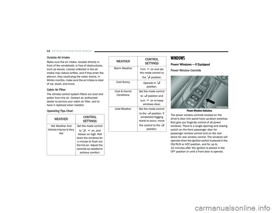
Power Window Switches
The power window controls located on the
driver's door trim panel have up-down switches
that give you fingertip control of all power
windows. There is a single opening and closing
switch on the front passenger door for
passenger window control and on the rear
doors for rear window control. The windows will
operate when the ignition switch is placed in the
ON/RUN or ACC position, and for up to
10 minutes after the ignition is placed in the
OFF position or until a front door is opened.
WEATHER CONTROL
SETTINGS
Hot Weather And
Vehicle Interior Is Very Hot Set the mode control
to , on, and
blower on high. Roll
down the windows for a minute to flush out
the hot air. Adjust the
controls as needed to achieve comfort.
Warm Weather Turn on and set
the mode control to
the position.
Cool Sunny Operate in
position.
Cool & Humid Conditions Set the mode control
to position and
turn on to keep windows clear.
Cold Weather Set the mode control to the position. If windshield fogging
starts to occur, move
the control to the position.
WEATHER CONTROL
SETTINGS
2020_RAM_CHASSIS_CAB_OM_USA=GUID-6C67832B-7839-4CCF-BEFC-CDF988F949EA=1=en=.book Page 64
Page 160 of 516

158SAFETY
(Continued)
Enhanced Accident Response System
In the event of an impact, if the communication
network remains intact, and the power remains
intact, depending on the nature of the event,
the ORC will determine whether to have the
Enhanced Accident Response System perform
the following functions:
Cut off fuel to the engine (If Equipped)
Cut off battery power to the electric motor (If
Equipped)
Flash hazard lights as long as the battery has
power
Turn on the interior lights, which remain on
as long as the battery has power or for
15 minutes from the intervention of the
Enhanced Accident Response System.
Unlock the power door locks.
Your vehicle may also be designed to perform
any of these other functions in response to the
Enhanced Accident Response System:
Turn off the Fuel Filter Heater, Turn off the
HVAC Blower Motor, Close the HVAC Circula -
tion Door
Cut off battery power to the:
Engine
Electric Motor (if equipped)
Electric power steering
Brake booster
Electric park brake
Automatic transmission gear selector
Horn
Front wiper
Headlamp washer pump
NOTE:
After an accident, remember to place the igni -
tion to the STOP (OFF/LOCK) position and
remove the key from the ignition switch to avoid
draining the battery. Carefully check the vehicle
for fuel leaks in the engine compartment and on
the ground near the engine compartment and
fuel tank before resetting the system and
starting the engine. If there are no fuel leaks or
damage to the vehicle electrical devices (e.g.
headlights) after an accident, reset the system
by following the procedure described below. If
you have any doubt, contact an authorized
dealer.
Enhanced Accident Response System Reset
Procedure
In order to reset the Enhanced Accident
Response System functions after an event, the
ignition switch must be changed from ignition
START or ON/RUN to ignition OFF. Carefully
check the vehicle for fuel leaks in the engine
compartment and on the ground near the
engine compartment and fuel tank before reset -
ting the system and starting the engine.
Maintaining Your Air Bag System
WARNING!
Modifications to any part of the air bag
system could cause it to fail when you need
it. You could be injured if the air bag system
is not there to protect you. Do not modify
the components or wiring, including adding
any kind of badges or stickers to the
steering wheel hub trim cover or the upper
passenger side of the instrument panel. Do
not modify the front bumper, vehicle body
structure, or add aftermarket side steps or
running boards.
2020_RAM_CHASSIS_CAB_OM_USA=GUID-6C67832B-7839-4CCF-BEFC-CDF988F949EA=1=en=.book Page 158
Page 192 of 516

190STARTING AND OPERATING
3. While the "Wait to Start" telltale is on, the
instrument cluster will additionally display a
gauge or bar whose initial length represents
the full "Wait to Start" time period. Its length
will decrease until it disappears when the
"Wait to Start" time has elapsed.
4. After the engine “Wait to Start” telltale goes off, the engine will automatically crank. 5. After engine start-up, check to see that
there is oil pressure.
6. Release the parking brake and drive.
NOTE:
Engine idle speed will automatically increase
to 1,000 RPM and engage the Variable
Geometry Turbocharger at low coolant
temperatures to improve engine warm-up.
The engine will not automatically crank after
the engine "Wait to Start" telltale goes off if a
door or the hood is ajar.
If the engine stalls, or if the ignition switch is
left ON for more than two minutes after the
“Wait to Start” telltale goes out, reset the
intake air heater by turning the ignition
switch to the OFF position for at least 5
seconds and then back ON. Repeat steps 1
through 7 of “Keyless Enter-N-Go Starting
Procedure – Engine Manifold Air Tempera -
ture Below 66°F (19°C).”
Extreme Cold Weather
The Cummins Turbo Diesel engine is equipped
with several features designed to assist cold
weather starting and operation:
The engine block heater is a resistance
heater installed in the water jacket of the
engine just above and behind the oil filter. It
requires a 110–115 Volt AC electrical outlet
with a grounded, three-wire extension cord.
NOTE:
The engine block heater cord is a factory
installed option. If your vehicle is not equipped,
heater cords are available from your authorized
Mopar dealer.
A 12 Volt heater built into the fuel filter hous -
ings aid in preventing fuel gelling. It is
controlled by a built-in thermostat.
An intake air heater system both improves
engine starting and reduces the amount of
white smoke generated by a warming engine.
CAUTION!
If the “Water in Fuel Indicator Light” remains
on, DO NOT START the engine before you
drain the water from the fuel filters to avoid
engine damage. Refer to “Draining Fuel/
Water Separator Filter” in “Servicing And
Maintenance” for further information.
CAUTION!
Do not crank engine for more than 25
seconds at a time or starter motor damage
may result. Turn the ignition switch to the OFF
position and wait at least two minutes for the
starter to cool before repeating start
procedure.
2020_RAM_CHASSIS_CAB_OM_USA=GUID-6C67832B-7839-4CCF-BEFC-CDF988F949EA=1=en=.book Page 190
Page 193 of 516

STARTING AND OPERATING191
Normal Starting Procedure — Engine
Manifold Air Temperature Above 66°F
(19°C)
Observe the instrument panel cluster lights
when starting the engine.
1. Always apply the parking brake.
2. Shift into PARK for an automatic transmis -
sion.
3. Place the ignition switch in the ON position and watch the instrument panel cluster
lights. 4. Place the ignition switch in the START posi
-
tion and crank the engine. Do not press the
accelerator during starting.
5. Check that the oil pressure warning light has turned off.
6. Release the parking brake.
Starting Procedure — Engine Manifold Air
Temperature 0°F To 66°F (–18°C to 19°C)
NOTE:
The temperature displayed in the instrument
cluster does not necessarily reflect the engine
manifold air temperature. Refer to “Instrument
Cluster Display” in “Getting To Know Your
Instrument Panel” for further information.
When engine temperatures fall below 66°F
(19°C) the “Wait To Start” telltale will remain on
indicating the intake air heater system is active.
Follow the steps in the “Normal Starting” proce -
dure except:
1. The “Wait to Start” telltale will remain on for a period of time that varies depending
on the engine temperature.
2. While the “Wait to Start” telltale is on, the instrument cluster will additionally display a
gauge or bar whose initial length represents
the full “Wait to Start” time period. Its length
will decrease until it disappears when the
“Wait to Start” time has elapsed.
CAUTION!
If the “Water in Fuel Indicator Light” remains
on, DO NOT START the engine before you
drain the water from the fuel filters to avoid
engine damage. Refer to “Draining Fuel/
Water Separator Filter” in “Servicing And
Maintenance” for further information.
CAUTION!
Do not crank engine for more than 25
seconds at a time or starter motor damage
may result. Turn the ignition switch to the OFF
position and wait at least two minutes for the
starter to cool before repeating start
procedure.
5
2020_RAM_CHASSIS_CAB_OM_USA=GUID-6C67832B-7839-4CCF-BEFC-CDF988F949EA=1=en=.book Page 191
Page 194 of 516

192STARTING AND OPERATING
3. After the “Wait to Start” telltale goes off,
place the ignition switch in the START posi -
tion. Do not press the accelerator during
starting.
4. After engine start-up, check that the oil pressure warning light has turned off.
5. Release the parking brake and drive. NOTE:
Engine idle speed will automatically increase
to 1,000 RPM and engage the Variable
Geometry Turbocharger at low coolant
temperatures to improve engine warm-up.
Automatic equipped vehicles with optional
Keyless Enter-N-Go – If the ENGINE START/
STOP button is pushed once while in park
with the ignition off and driver’s foot on the
brake pedal, the vehicle will automatically
crank and start after the “Wait to Start” time
has elapsed. If it is desired to abort the start
process before it completes, the driver’s foot
should be fully removed from the brake pedal
prior to pushing the start button again in
order for the ignition to move directly to off.
If the engine stalls, or if the ignition switch is
left ON for more than two minutes after the
“Wait To Start” telltale goes out, reset the
intake air heater by turning the ignition
switch to the OFF position for at least five
seconds and then back ON. Repeat steps 1
through 5 of “Starting Procedure – Engine
Manifold Air Temperature Below 66°F
(19°C).”
Starting Procedure — Engine Manifold Air
Temperature Below 0°F (-18°C)
In extremely cold weather below 0°F (-18°C) it
may be beneficial to cycle the intake air heater
twice before attempting to start the engine. This
can be accomplished by turning the ignition OFF
for at least five seconds and then back ON after
the “Wait to Start” telltale has turned off, but
before the engine is started. However, exces
-
sive cycling of the intake air heater will result in
damage to the heater elements or reduced
battery voltage.
NOTE:
If multiple pre-heat cycles are used before
starting, additional engine run time may be
required to maintain battery state of charge at
a satisfactory level.
CAUTION!
If the “Water in Fuel Indicator Light” remains
on, DO NOT START the engine before you
drain the water from the fuel filters to avoid
engine damage. Refer to “Draining Fuel/
Water Separator Filter” in “Servicing And
Maintenance” for further information.
CAUTION!
Do not crank engine for more than 25
seconds at a time or starter motor damage
may result. Turn the ignition switch to the OFF
position and wait at least two minutes for the
starter to cool before repeating start
procedure.
2020_RAM_CHASSIS_CAB_OM_USA=GUID-6C67832B-7839-4CCF-BEFC-CDF988F949EA=1=en=.book Page 192
Page 200 of 516

198STARTING AND OPERATING
Idle-Up Feature
The driver-controlled high idle speed feature will
help increase cylinder temperatures and
provide additional cab heat, however, excessive
idling may still cause the exhaust aftertreat -
ment system to not properly regenerate.
Extended periods of idle time should be
avoided.
The Idle-Up feature uses the Speed Control
switches to increase engine idle speed and
quickly warm the vehicle's interior.
1. With the transmission in PARK, the parking brake applied, and the engine running,
turn on the speed control, then push the
SET switch.
2. The engine RPM will go up to 1,100 RPM. To increase the RPM, push and hold the
ACCEL/RESUME switch and the idle speed
will increase to approximately 1,500 RPM.
To decrease the RPM, push and hold the
DECEL switch and the idle speed will
decrease to approximately 1,100 RPM.
3. To cancel the Idle–Up feature, either push the CANCEL switch, push the ON/OFF
switch, or press the brake pedal.
Noise
Diesel engines can create noises that may
seem as a concern. The nature of a diesel
engine is compression ignition where
compressed air and fuel are mixed and ignited.
Weather, Barometric Pressure, Altitude and
Temperature will affect how fuel is ignited in the
engine. Engine’s will sound different from day to
day or previous model years. Clicking, ticking, or
light knocking is normal and will change from
day to day, as the engine breaks in, and can
vary with changes in ambient temperature, this
is normal. Diesel equipped vehicles also have
an exhaust aftertreatment system to reduce
emissions utilizing a Diesel Particulate Filter
(DPF) and a Selective Reduction Catalyst (SCR).
The SCR reduces Nox using the Diesel Exhaust
Fluid (DEF) system. DEF is injected directly into
the SCR through an dosing module. This
process will create a clicking sound and at
times, will make noise even with the vehicle shut off. This is normal as the DEF dosing
module is purging DEF. Fuel pump noise may
increase during low speed/light load conditions
when ambient temperature is above 100°F
(38°C), and when fuel tank level is below 10%.
This is a normal condition of the fuel system and
controls strategy. If at any time the check
engine light is on, please visit an authorized
dealer.
Stopping The Engine
Idle the engine a few minutes before routine
shutdown. After full load operation, idle the
engine three to five minutes before shutting it
down. This idle period will allow the lubricating
oil and coolant to carry excess heat away from
the combustion chamber, bearings, internal
components, and turbocharger. This is espe
-
cially important for turbocharged, charge
air-cooled engines. Refer to the following chart
for proper engine shutdown:
2020_RAM_CHASSIS_CAB_OM_USA=GUID-6C67832B-7839-4CCF-BEFC-CDF988F949EA=1=en=.book Page 198
Page 271 of 516

STARTING AND OPERATING269
REFUELING THE VEHICLE — DIESEL ENGINE
NOTE:
When the fuel nozzle “clicks” or shuts off, the
fuel tank is full.
Tighten the fuel filler cap until you hear a
“clicking” sound. This is an indication that the
fuel filler cap is properly tightened.
Make sure that the fuel filler cap is tightened
each time the vehicle is refueled.
Fuel Filler Cap
If the fuel filler cap is lost or damaged, be sure
the replacement cap is for use with this vehicle.
Avoid Using Contaminated Fuel
Fuel that is contaminated by water or dirt can
cause severe damage to the engine fuel
system. Proper maintenance of the engine fuel
filter and fuel tank is essential. Refer to “Dealer
Service” in “Servicing And Maintenance” for
further information.
Bulk Fuel Storage — Diesel Fuel
If you store quantities of fuel, good mainte -
nance of the stored fuel is also essential. Fuel
contaminated with water will promote the
growth of “microbes.” These microbes form
“slime” that will clog the fuel filtration system
and lines. Drain condensation from the supply
tank and change the line filter on a regular
basis.
NOTE:
When a diesel engine is allowed to run out of
fuel, air is pulled into the fuel system.
If the vehicle will not start, refer to “Priming If
The Engine Has Run Out Of Fuel” in “Servicing
And Maintenance” for further information.CAUTION!
To avoid fuel spillage and overfilling, do not
“top off” the fuel tank after filling.
WARNING!
A fire may result if gasoline is pumped into a
portable container that is inside of a vehicle.
You could be burned. Always place gas
containers on the ground while filling.
WARNING!
Never have any smoking materials lit in or
near the vehicle when the fuel filler cap is
removed or the tank filled.
Never add fuel to the vehicle when the
engine is running.
CAUTION!
Damage to the fuel system or emission
control system could result from using an
improper fuel tank filler tube cap. A poorly
fitting cap could let impurities into the fuel
system.
WARNING!
Do not open the high pressure fuel system
with the engine running. Engine operation
causes high fuel pressure. High pressure fuel
spray can cause serious injury or death.
5
2020_RAM_CHASSIS_CAB_OM_USA=GUID-6C67832B-7839-4CCF-BEFC-CDF988F949EA=1=en=.book Page 269
Page 287 of 516

STARTING AND OPERATING285
Automatic Transmission
The DRIVE range can be selected when towing.
The transmission controls include a drive
strategy to avoid frequent shifting when towing.
However, if frequent shifting does occur while in
DRIVE, select TOW/HAUL mode or select a lower
gear range (using the Electronic Range Select
(ERS) shift control).
NOTE:
Using TOW/HAUL mode or selecting a lower
gear range (using the ERS shift control) while
operating the vehicle under heavy loading
conditions will improve performance and
extend transmission life by reducing excessive
shifting and heat build up. This action will also
provide better engine braking.
Six-Speed Automatic Transmission Only
When towing a loaded trailer up steep grades at
low speeds (20 mph [32 km/h] or below),
holding your vehicle in first gear (using the ERS
shift control) can help to avoid transmission
overheating. If you regularly tow a trailer for more than
45 minutes of continuous operation, then
change the automatic transmission fluid and
filter(s) as specified for "police, taxi, fleet, or
frequent trailer towing." Refer to the “Mainte
-
nance Plan” for the proper maintenance inter -
vals.
NOTE:
Check the automatic transmission fluid level
before towing (Six-speed automatic only).
Tow/Haul Mode
To reduce potential for automatic transmission
overheating, activate TOW/HAUL mode when
driving in hilly areas, or select a lower gear
range (using the Electronic Range Select (ERS)
shift control) on more severe grades.
Speed Control — If Equipped
Do not use on hilly terrain or with heavy
loads.
When using the Speed Control, if you experi -
ence speed drops greater than 10 mph
(16 km/h), disengage until you can get back
to cruising speed.
Use Speed Control in flat terrain and with
light loads to maximize fuel efficiency.
Cooling System
To reduce potential for engine and transmission
overheating, take the following actions:
City Driving
In city traffic — while stopped, place the trans -
mission in NEUTRAL, but do not increase
engine idle speed.
Highway Driving
Reduce speed.
Temporarily turn off air conditioning.
5
2020_RAM_CHASSIS_CAB_OM_USA=GUID-6C67832B-7839-4CCF-BEFC-CDF988F949EA=1=en=.book Page 285