climate control RAM CHASSIS CAB 2020 Owners Manual
[x] Cancel search | Manufacturer: RAM, Model Year: 2020, Model line: CHASSIS CAB, Model: RAM CHASSIS CAB 2020Pages: 516, PDF Size: 16.57 MB
Page 5 of 516
3
EXTERIOR LIGHTS ...............................................44 Multifunction Lever ...................................... 44
Headlight Switch .......................................... 44
Daytime Running Lights (DRLs) ................. 45
High/Low Beam Switch ............................... 45
Automatic High Beam Headlamp
Control — If Equipped .................................. 45 Flash-To-Pass ............................................. 46
Automatic Headlights — If Equipped .......... 46
Parking Lights And Panel Lights ................. 46
Directional LED Headlamp System —
If Equipped ................................................... 46 Headlights On With Wipers (Available With
Automatic Headlights Only) ......................... 46 Headlight Delay ............................................ 47
Lights-On Reminder ..................................... 47
Front Fog Lights — If Equipped .................. 47
Turn Signals ............................................. 47
Lane Change Assist — If Equipped ............. 47
Cargo Lights/Trailer Spotter Lights —
If Equipped ................................................... 47 Battery Saver................................................ 48
INTERIOR LIGHTS ................................................48
Courtesy Lights ............................................ 48
Illuminated Entry ......................................... 49
WINDSHIELD WIPERS AND WASHERS ............50
Windshield Wipers ..................................... 50
Rain Sensing Wipers — If Equipped ........... 51 CLIMATE CONTROLS ........................................... 51
Manual Climate Control Overview ............ 52
Automatic Climate Control Overview .......... 55
Climate Control Functions........................... 62
Automatic Temperature Control (ATC) ...... 62
Operating Tips ............................................. 63
WINDOWS ............................................................ 64
Power Windows — If Equipped .................... 64
Wind Buffeting ............................................ 66
HOOD .................................................................... 66
To Open The Hood ...................................... 66
To Close The Hood ....................................... 67
GARAGE DOOR OPENER — IF EQUIPPED ........ 67
Before You Begin Programming
HomeLink® .................................................. 68 Canadian/Gate Operator Programming ..... 70
Using HomeLink®........................................ 71
Security......................................................... 71
Troubleshooting Tips ................................... 71
General Information .................................... 72
INTERNAL EQUIPMENT ........................................ 72
Storage ......................................................... 72
Cupholders .................................................. 77
Electrical Power Outlets ............................ 78
Power Inverter — If Equipped ..................... 80
Wireless Charging Pad — If Equipped ........ 81
Overhead Sunglass Storage ....................... 81
GETTING TO KNOW YOUR INSTRUMENT PANEL
BASE / MIDLINE INSTRUMENT CLUSTER..........82Base / Midline Instrument Cluster
Descriptions ................................................. 83
PREMIUM INSTRUMENT CLUSTER .....................85
Premium Instrument Cluster
Descriptions ................................................. 86
DIESEL INSTRUMENT CLUSTER .........................87
DIESEL INSTRUMENT CLUSTER ................ 88
INSTRUMENT CLUSTER .......................................90
Diesel INSTRUMENT CLUSTER .................. 91
INSTRUMENT CLUSTER DISPLAY .......................92
Instrument Cluster Display Controls .......... 92
Oil Life Reset ............................................... 93
Display Menu Items ..................................... 94
Diesel Messages And Warnings —
6.7L Cummins Diesel Engine ................... 103 Battery Saver On/Battery Saver Mode
Message — Electrical Load Reduction Actions
— If Equipped .......................................... 107
WARNING LIGHTS AND MESSAGES ............... 108
Red Warning Lights ................................... 108
Yellow Warning Lights ............................... 111Yellow Indicator Lights .............................. 115
Green Indicator Lights ............................... 116White Indicator Lights ............................... 117Blue Indicator Lights ................................. 118
2020_RAM_CHASSIS_CAB_OM_USA=GUID-6C67832B-7839-4CCF-BEFC-CDF988F949EA=1=en=.book Page 3
Page 10 of 516
8
FUEL REQUIREMENTS — GAS ENGINE .......... 399 6.4L Engine ................................................399
Reformulated Gasoline ........................ 399Materials Added To Fuel .........................400
Gasoline/Oxygenate Blends ....................400
Do Not Use E-85 In Non-Flex
Fuel Vehicles ..............................................400 CNG And LP Fuel System
Modifications .............................................400 MMT In Gasoline ........................................401
Fuel System Cautions ................................401Carbon Monoxide Warnings ....................401
FUEL REQUIREMENTS – DIESEL ENGINE .. 402
Fuel Specifications ...................................402
Biodiesel Fuel Requirements ....................403
VEHICLE SPECIFCATIONS ................................. 404
FLUID CAPACITIES — GAS ENGINE ............... 405
FLUID CAPACITIES — DIESEL ENGINE ......... 405
FLUIDS AND LUBRICANTS — GAS ENGINE .... 407 Engine ........................................................ 407
Chassis .....................................................409
FLUIDS AND LUBRICANTS —
DIESEL ENGINE ................................................. 410
Engine ........................................................ 410
Chassis .......................................................412
MOPAR ACCESSORIES .................................... 413
Authentic Accessories By Mopar .............413
MULTIMEDIA
UCONNECT SYSTEMS .......................................414
CYBERSECURITY ............................................... 414
UCONNECT SETTINGS .......................................415 Uconnect 3 Settings .................................. 415Uconnect 4/4C/4C NAV Settings ............. 430Uconnect 4C NAV With 12-inch Display
Settings ...................................................... 449
SAFETY AND GENERAL INFORMATION ........... 467
Safety Guidelines....................................... 467
UCONNECT 3 WITH 5-INCH DISPLAY ..............468
Introduction................................................ 468
Radio Mode ................................................ 469
Media Mode ............................................... 472Phone Mode ............................................... 474
STEERING WHEEL AUDIO CONTROLS — IF
EQUIPPED ......................................................... 481
Radio Operation ......................................... 481
Media Mode ............................................... 481
IPOD®/USB/MP3 CONTROL —
IF EQUIPPED ....................................................481
RADIO OPERATION AND MOBILE PHONES ...483
Regulatory And Safety Information........... 484 VOICE RECOGNITION QUICK TIPS ................. 485
Introducing Uconnect ................................ 485
Get Started................................................. 485Basic Voice Commands ............................ 485Radio .......................................................... 486
Media ......................................................... 488Phone ......................................................... 489Voice Text Reply — If Equipped ................. 490
Climate (4C/4C NAV)................................. 491Navigation (4C NAV) .................................. 492
SiriusXM Guardian™ (4C/4C NAV) —
If Equipped ................................................. 492 Register (4C/4C NAV)................................ 493
Mobile App (4C/4C NAV) ........................... 493
SiriusXM® Travel Link (4C NAV) ............... 494Siri® Eyes Free — If Equipped ................. 495
Using Do Not Disturb ................................ 496
Android Auto™ — If Equipped .................. 496Apple CarPlay® — If Equipped ................. 497
General Information .................................. 498
Additional Information............................... 499
2020_RAM_CHASSIS_CAB_OM_USA=GUID-6C67832B-7839-4CCF-BEFC-CDF988F949EA=1=en=.book Page 8
Page 36 of 516
34GETTING TO KNOW YOUR VEHICLE
When you remove the key fob from the igni -
tion, the driver’s seat will move to a position
0.3 inches (7.7 mm) forward of the rear stop if the driver’s seat position is between
0.9 inches and 2.7 inches (22.7 mm and
67.7 mm) forward of the rear stop. The seat
will return to its previously set position when
you place the ignition to the ACC or RUN posi -
tion.
The Easy Entry/Easy Exit feature is disabled
when the driver’s seat position is less than
0.9 inches (22.7 mm) forward of the rear stop. At this position, there is no benefit to
the driver by moving the seat for Easy Exit or
Easy Entry.
Each stored memory setting will have an associ -
ated Easy Entry and Easy Exit position.
NOTE:
The Easy Entry/Exit feature is not enabled when
the vehicle is delivered from the factory. The
Easy Entry/Exit feature is enabled (or later
disabled) through the programmable features
in the Uconnect system. Refer to “Uconnect
Settings” in “Multimedia” for further informa -
tion.
Heated Seats — If Equipped
On some models, the front and rear seats may
be equipped with heaters located in the seat
cushions and seat backs.
Front Heated Seats
The heated seats control buttons are located on
the center instrument panel below the touch -
screen, and are also located within the climate
or controls screen of the touchscreen.
Push the heated seat button once to turn
the HI setting on.
Push the heated seat button a second
time to turn the MED setting on.
Push the heated seat button a third time
to turn the LO setting on.
Push the heated seat button a fourth time
to turn the heating elements off.
NOTE:
The engine must be running for the heated
seats to operate.
The level of heat selected will stay on until
the operator changes it.
Vehicles Equipped With Remote Start
On models that are equipped with remote start,
the driver’s seat can be programmed to come
on during a remote start.
This feature can be programmed through the
Uconnect system. Refer to “Uconnect Settings”
in “Multimedia” for further information.
WARNING!
Persons who are unable to feel pain to the
skin because of advanced age, chronic
illness, diabetes, spinal cord injury, medica -
tion, alcohol use, exhaustion or other phys -
ical condition must exercise care when
using the seat heater. It may cause burns
even at low temperatures, especially if
used for long periods of time.
Do not place anything on the seat or seat -
back that insulates against heat, such as a
blanket or cushion. This may cause the seat
heater to overheat. Sitting in a seat that has
been overheated could cause serious
burns due to the increased surface
temperature of the seat.
2020_RAM_CHASSIS_CAB_OM_USA=GUID-6C67832B-7839-4CCF-BEFC-CDF988F949EA=1=en=.book Page 34
Page 37 of 516
GETTING TO KNOW YOUR VEHICLE35
Rear Heated Seats
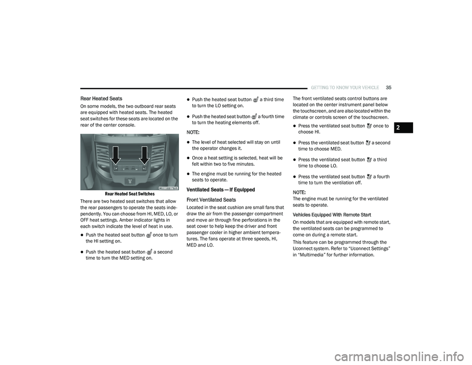
On some models, the two outboard rear seats
are equipped with heated seats. The heated
seat switches for these seats are located on the
rear of the center console.
Rear Heated Seat Switches
There are two heated seat switches that allow
the rear passengers to operate the seats inde -
pendently. You can choose from HI, MED, LO, or
OFF heat settings. Amber indicator lights in
each switch indicate the level of heat in use.
Push the heated seat button once to turn
the HI setting on.
Push the heated seat button a second
time to turn the MED setting on.
Push the heated seat button a third time
to turn the LO setting on.
Push the heated seat button a fourth time
to turn the heating elements off.
NOTE:
The level of heat selected will stay on until
the operator changes it.
Once a heat setting is selected, heat will be
felt within two to five minutes.
The engine must be running for the heated
seats to operate.
Ventilated Seats — If Equipped
Front Ventilated Seats
Located in the seat cushion are small fans that
draw the air from the passenger compartment
and move air through fine perforations in the
seat cover to help keep the driver and front
passenger cooler in higher ambient tempera -
tures. The fans operate at three speeds, HI,
MED and LO. The front ventilated seats control buttons are
located on the center instrument panel below
the touchscreen, and are also located within the
climate or controls screen of the touchscreen.
Press the ventilated seat button once to
choose HI.
Press the ventilated seat button a second
time to choose MED.
Press the ventilated seat button a third
time to choose LO.
Press the ventilated seat button a fourth
time to turn the ventilation off.
NOTE:
The engine must be running for the ventilated
seats to operate.
Vehicles Equipped With Remote Start
On models that are equipped with remote start,
the ventilated seats can be programmed to
come on during a remote start.
This feature can be programmed through the
Uconnect system. Refer to “Uconnect Settings”
in “Multimedia” for further information.
2
2020_RAM_CHASSIS_CAB_OM_USA=GUID-6C67832B-7839-4CCF-BEFC-CDF988F949EA=1=en=.book Page 35
Page 40 of 516

38GETTING TO KNOW YOUR VEHICLE
STEERING WHEEL
Tilt Steering Column
This feature allows you to tilt the steering
column upward or downward. The tilt lever is
located on the steering column, below the multi -
function lever.
Pull the lever toward the steering wheel to
unlock the steering column. With one hand
firmly on the steering wheel, move the steering
column up or down, as desired. Release the
lever to lock the steering column firmly in place.
Tilt Steering Lever
Heated Steering Wheel — If Equipped
The steering wheel contains a heating element
that helps warm your hands in cold weather.
The heated steering wheel has only one
temperature setting. Once the heated steering
wheel has been turned on, it will stay on until
the operator turns it off. The heated steering
wheel may not turn on when it is already warm.
The heated steering wheel control button is
located on the center instrument panel below
the touchscreen, as well as within the climate or
controls screen of the touchscreen.
Press the heated steering wheel button
once to turn the heating element on.
Press the heated steering wheel button a
second time to turn the heating element off. NOTE:
The engine must be running for the heated
steering wheel to operate.
Vehicles Equipped With Remote Start
On models that are equipped with remote start,
the heated steering wheel can be programmed
to come on during a remote start.
This feature can be programmed through the
Uconnect system. Refer to “Uconnect Settings”
in “Multimedia” for further information.
WARNING!
Do not adjust the steering column while
driving. Adjusting the steering column while
driving or driving with the steering column
unlocked, could cause the driver to lose
control of the vehicle. Failure to follow this
warning may result in serious injury or death.
WARNING!
Persons who are unable to feel pain to the
skin because of advanced age, chronic
illness, diabetes, spinal cord injury, medica
-
tion, alcohol use, exhaustion, or other phys -
ical conditions must exercise care when
using the steering wheel heater. It may
cause burns even at low temperatures,
especially if used for long periods.
Do not place anything on the steering wheel
that insulates against heat, such as a
blanket or steering wheel covers of any type
and material. This may cause the steering
wheel heater to overheat.
2020_RAM_CHASSIS_CAB_OM_USA=GUID-6C67832B-7839-4CCF-BEFC-CDF988F949EA=1=en=.book Page 38
Page 45 of 516

GETTING TO KNOW YOUR VEHICLE43
A small blindspot mirror is located next to main
mirror and can be adjusted separately.
Blindspot Mirror
Heated Mirrors — If Equipped
These mirrors are heated to melt frost
or ice. This feature will be activated
whenever you turn on the rear window
defroster (if equipped).
Refer to “Climate Controls” in this chapter for
further information.
Tilt Side Mirrors In Reverse — If Equipped
Tilt Side Mirrors In Reverse provides automatic
outside mirror positioning which will aid the
driver’s view of the ground rearward of the front
doors. The outside mirrors will move slightly
downward from the present position when the
vehicle is shifted into REVERSE. The outside
mirrors will then return to the original position
when the vehicle is shifted out of the REVERSE
position. Each stored memory setting will have
an associated Tilt Side Mirrors In Reverse posi -
tion.
NOTE:
The Tilt Side Mirrors In Reverse feature is not
turned on when delivered from the factory.
This feature can be programmed through the
Uconnect system. Refer to “Uconnect Settings”
in “Multimedia” for further information.
Outside Mirrors Folding Feature
All outside mirrors are designed to be able to be
manually folded both forward and rearward to
prevent damage.
Folding Mirror
CAUTION!
It is recommended to fold the mirrors into the
full rearward position to resist damage when
entering a car wash or a narrow location.
2
2020_RAM_CHASSIS_CAB_OM_USA=GUID-6C67832B-7839-4CCF-BEFC-CDF988F949EA=1=en=.book Page 43
Page 52 of 516

50GETTING TO KNOW YOUR VEHICLE
WINDSHIELD WIPERS AND WASHERS
Windshield Wipers
The wipers and washers are operated by a
switch in the multifunction lever. Turn the end of
the lever to select the desired wiper speed.
Windshield Wiper/Washer Switch
Rotate the end of the lever upward, to the first
detent past the intermittent settings for
low-speed wiper operation. Rotate the end of
the lever upward to the second detent past the
intermittent settings for high-speed wiper oper -
ation.
Intermittent Wiper System
The intermittent feature of this system was
designed for use when weather conditions
make a single wiping cycle, with a variable pause between cycles, desirable. For maximum
delay between cycles, rotate the control knob
upward to the first detent.
The delay interval decreases as you rotate the
knob until it enters the low continual speed
position. The delay can be regulated from a
maximum of about 18 seconds between cycles,
to a cycle every one second. The delay intervals
will double in duration when the vehicle speed
is 10 mph (16 km/h) or less.
Windshield Washers
To use the windshield washer, push the washer
knob, located on the end of the multifunction
lever, inward to the second detent. Washer fluid
will be sprayed and the wiper will operate for
two to three cycles after the washer knob is
released from this position.
If the washer knob is depressed while in the
delay range, the wiper will operate for several
seconds after the washer knob is released. It
will then resume the intermittent interval previ
-
ously selected. If the washer knob is pushed
while in the off position, the wiper will turn on
and cycle approximately three times after the
wash knob is released.
To prevent freeze-up of your windshield washer
system in cold weather, select a solution or mixture that meets or exceeds the temperature
range of your climate. This rating information
can be found on most washer fluid containers.
Mist Feature
When a single wipe to clear off road mist or
spray from a passing vehicle is needed, push
the washer knob, located on the end of the
multifunction lever, inward to the first detent
and release. The wipers will cycle one time and
automatically shut off.
NOTE:
The mist feature does not activate the washer
pump; therefore, no washer fluid will be sprayed
on the windshield. The wash function must be
used in order to spray the windshield with
washer fluid.
WARNING!
Sudden loss of visibility through the
windshield could lead to a collision. You might
not see other vehicles or other obstacles. To
avoid sudden icing of the windshield during
freezing weather, warm the windshield with
the defroster before and during windshield
washer use.
2020_RAM_CHASSIS_CAB_OM_USA=GUID-6C67832B-7839-4CCF-BEFC-CDF988F949EA=1=en=.book Page 50
Page 53 of 516
GETTING TO KNOW YOUR VEHICLE51
Rain Sensing Wipers — If Equipped
This feature senses moisture on the windshield
and automatically activates the wipers for the
driver. The feature is especially useful for road
splash or overspray from the windshield
washers of the vehicle ahead. Rotate the end of
the multifunction lever to one of five settings to
activate this feature.
NOTE:
This feature can be programmed through the
Uconnect system. Refer to “Uconnect Settings”
in “Multimedia” for further information.
The sensitivity of the system can be adjusted
with the multifunction lever. Wiper delay posi -
tion 1 is the least sensitive, and wiper delay
position 5 is the most sensitive. Position 3
should be used for normal rain conditions. Posi -
tions 1 and 2 can be used if the driver desires
less wiper sensitivity. Positions 4 and 5 can be
used if the driver desires more sensitivity. Place
the wiper switch in the O (off) position when not
using the system. NOTE:The Rain Sensing feature will not operate
when the wiper switch is in the low or
high-speed position.
The Rain Sensing feature may not function
properly when ice, or dried salt water is
present on the windshield.
Use of Rain-X or products containing wax or
silicone may reduce Rain Sensing perfor
-
mance.
The Rain Sensing system has protection
features for the wiper blades and arms, and will
not operate under the following conditions:
Low Ambient Temperature — When the igni-
tion is first placed in the ON position, the Rain
Sensing system will not operate until the
wiper switch is moved, vehicle speed is
greater than 0 mph (0 km/h), or the outside
temperature is greater than 32°F (0°C).
Transmission In NEUTRAL Position — When
the ignition is ON, and the transmission is in
the NEUTRAL position, the Rain Sensing
system will not operate until the wiper switch
is moved, vehicle speed is greater than
5 mph (8 km/h), or the gear selector is
moved out of the NEUTRAL position.
Remote Start Mode Inhibit — On vehicles
equipped with Remote Starting system, Rain
Sensing wipers are not operational when the
vehicle is in the remote start mode. Once the
operator is in the vehicle and has placed the
ignition switch in the RUN position, Rain
Sensing wiper operation can resume, if it has
been selected, and no other inhibit condi -
tions (mentioned previously) exist.
CLIMATE CONTROLS
The Climate Control system allows you to regu -
late the temperature, air flow, and direction of
air circulating throughout the vehicle. The
controls are located on the touchscreen (if
equipped), on the sides of the touchscreen, or
on the instrument panel below the radio.
2
2020_RAM_CHASSIS_CAB_OM_USA=GUID-6C67832B-7839-4CCF-BEFC-CDF988F949EA=1=en=.book Page 51
Page 54 of 516

52GETTING TO KNOW YOUR VEHICLE
Manual Climate Control Overview
Manual Climate Controls
Icon Description
MAX A/C Setting
Set the Temperature Control Knob to the MAX A/C setting to change the current setting to the coldest output of air. Moving
the temperature control knob away from the MAX A/C setting causes the MAX A/C operation to exit.
A/C Button
Push the A/C button to engage the Air Conditioning (A/C). The A/C indicator illuminates when the A/C is on.
Recirculation Button
Press and release this button on the touchscreen, or push the button on the faceplate, to change the system between
Recirculation mode and outside air mode. The Recirculation indicator and the A/C indicator illuminate when the
Recirculation button is pushed. Recirculation can be used when outside conditions, such as smoke, odors, dust, or
humidity are present. Recirculation can be used in all modes except for Defrost. Recirculation may be unavailable if
conditions exist that could create fogging on the inside of the windshield. The A/C can be deselected manually without
disturbing the mode control selection. Continuous use of the Recirculation mode may make the inside air stuffy and
window fogging may occur. Extended use of this mode is not recommended.
2020_RAM_CHASSIS_CAB_OM_USA=GUID-6C67832B-7839-4CCF-BEFC-CDF988F949EA=1=en=.book Page 52
Page 55 of 516

GETTING TO KNOW YOUR VEHICLE53
Temperature Control
Temperature Control regulates the temperature of the air forced through the Climate Control system. The temperature
increases as you turn the temperature control knob clockwise. The temperature decreases as you turn the temperature
control knob counterclockwise.
Blower Control
Blower Control regulates the amount of air forced through the Climate Control system. There are seven blower speeds
available. The blower speed increases as you turn the blower control knob clockwise from the lowest blower setting. The
blower speed decreases as you turn the blower control knob counterclockwise.
Mode Control
Turn the Mode Control knob to adjust the airflow distribution. The airflow distribution mode can be adjusted so air comes
from the instrument panel outlets, floor outlets, defrost outlets and demist outlets. The Mode settings are as follows:
Panel Mode Panel Mode Air comes from the outlets in the instrument panel. Each of these outlets can be individually adjusted to direct the flow of
air. The air vanes of the center outlets and outboard outlets can be moved up and down or side to side to regulate airflow
direction. There is a shut off wheel located below the air vanes to shut off or adjust the amount of airflow from these
outlets.
Bi-Level Mode Bi-Level Mode Air comes from the instrument panel outlets and floor outlets. A slight amount of air is directed through the defrost and
side window demister outlets.
NOTE:
Bi-Level mode is designed under comfort conditions to provide cooler air out of the panel outlets and warmer air from the
floor outlets.
Icon Description
2
2020_RAM_CHASSIS_CAB_OM_USA=GUID-6C67832B-7839-4CCF-BEFC-CDF988F949EA=1=en=.book Page 53