warning light RAM CHASSIS CAB 2022 Owners Manual
[x] Cancel search | Manufacturer: RAM, Model Year: 2022, Model line: CHASSIS CAB, Model: RAM CHASSIS CAB 2022Pages: 428, PDF Size: 20.18 MB
Page 5 of 428
3
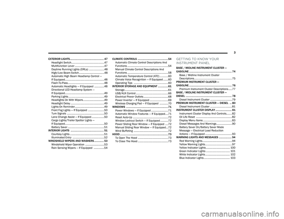
EXTERIOR LIGHTS.................................................. 47 Headlight Switch...............................................47
Multifunction Lever ..........................................47
Daytime Running Lights (DRLs) ......................48
High/Low Beam Switch....................................48
Automatic High Beam Headlamp Control —
If Equipped........................................................48
Flash-To-Pass....................................................48
Automatic Headlights — If Equipped ..............48
Directional LED Headlamp System —
If Equipped........................................................49
Parking Lights ...................................................49
Headlights On With Wipers ..............................49
Headlight Delay ................................................49
Lights-On Reminder..........................................49
Front Fog Lights — If Equipped .......................50
Turn Signals .....................................................50
Lane Change Assist — If Equipped ..................50
Cargo Lights/Trailer Spotter Lights —
If Equipped........................................................50
Battery Saver ....................................................51
INTERIOR LIGHTS ................................................. 51
Courtesy Lights .................................................51
Illuminated Entry .............................................52
WINDSHIELD WIPERS AND WASHERS .............. 53
Windshield Wiper Operation ...........................53
Rain Sensing Wipers — If Equipped ...............54 CLIMATE CONTROLS .............................................54
Automatic Climate Control Descriptions And
Functions ..........................................................54
Manual Climate Control Descriptions And
Functions ..........................................................58
Automatic Temperature Control (ATC) ............60
Climate Voice Recognition — If Equipped .......60
Operating Tips .................................................60
INTERIOR STORAGE AND EQUIPMENT ............... 61
Storage..............................................................61
USB/AUX Control ..............................................66
Electrical Power Outlets ...................................68
Power Inverter — If Equipped ..........................69
Wireless Charging Pad — If Equipped ............70
WINDOWS ..............................................................71
Power Windows — If Equipped ........................71
Automatic Window Features — If Equipped....71
Reset Auto-Up ..................................................72
Window Lockout Switch — If Equipped ...........72
Power Sliding Rear Window — If Equipped ....72
Manual Sliding Rear Window — If Equipped...72
Wind Buffeting .................................................72
HOOD .......................................................................73
To Open The Hood ...........................................73
To Close The Hood ...........................................73
GETTING TO KNOW YOUR
INSTRUMENT PANEL
BASE / MIDLINE INSTRUMENT CLUSTER —
GASOLINE ............................................................... 74Base / Midline Instrument Cluster
Descriptions...................................................... 75
PREMIUM INSTRUMENT CLUSTER —
GASOLINE ............................................................... 76
Premium Instrument Cluster Descriptions ..... 77
BASE / MIDLINE INSTRUMENT CLUSTER —
DIESEL .................................................................... 78
Diesel Instrument Cluster ............................... 79
PREMIUM INSTRUMENT CLUSTER — DIESEL ... 80
Diesel Instrument Cluster ............................... 81
INSTRUMENT CLUSTER DISPLAY ........................ 81
Instrument Cluster Display And Controls........ 82
Oil Life Reset ................................................... 82
Display Menu Items ......................................... 83
Diesel Messages And Warnings ...................... 90
Battery Saver On/Battery Saver Mode
Message — Electrical Load Reduction
Actions — If Equipped ...................................... 93
WARNING LIGHTS AND MESSAGES ................... 94
Red Warning Lights ..........................................94
Yellow Warning Lights ...................................... 97
Yellow Indicator Lights .................................. 100 Green Indicator Lights .................................. 101White Indicator Lights ................................... 102
Blue Indicator Lights ..................................... 103
22_DPF_OM_EN_USC_t.book Page 3
Page 8 of 428
6
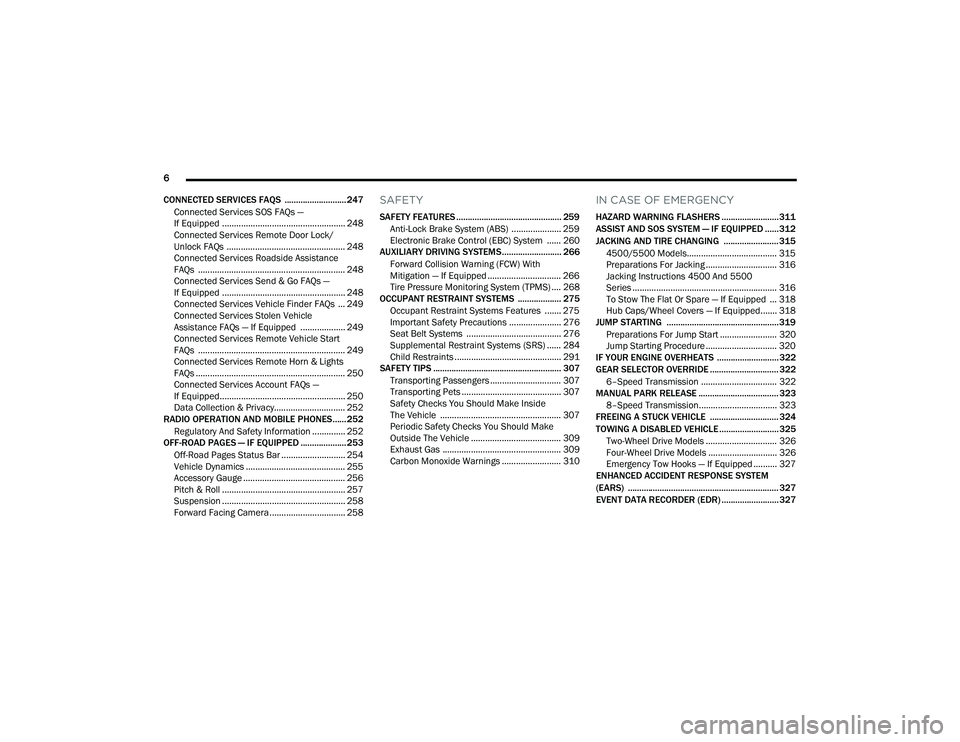
CONNECTED SERVICES FAQS ........................... 247 Connected Services SOS FAQs —
If Equipped .................................................... 248
Connected Services Remote Door Lock/
Unlock FAQs .................................................. 248
Connected Services Roadside Assistance
FAQs .............................................................. 248
Connected Services Send & Go FAQs —
If Equipped .................................................... 248
Connected Services Vehicle Finder FAQs ... 249
Connected Services Stolen Vehicle
Assistance FAQs — If Equipped ................... 249
Connected Services Remote Vehicle Start
FAQs .............................................................. 249
Connected Services Remote Horn & Lights
FAQs ............................................................... 250
Connected Services Account FAQs —
If Equipped..................................................... 250
Data Collection & Privacy.............................. 252
RADIO OPERATION AND MOBILE PHONES...... 252
Regulatory And Safety Information .............. 252
OFF-ROAD PAGES — IF EQUIPPED .................... 253
Off-Road Pages Status Bar ........................... 254
Vehicle Dynamics .......................................... 255
Accessory Gauge ........................................... 256Pitch & Roll .................................................... 257
Suspension .................................................... 258
Forward Facing Camera ................................ 258
SAFETY
SAFETY FEATURES .............................................. 259
Anti-Lock Brake System (ABS) ..................... 259
Electronic Brake Control (EBC) System ...... 260
AUXILIARY DRIVING SYSTEMS.......................... 266
Forward Collision Warning (FCW) With
Mitigation — If Equipped ............................... 266
Tire Pressure Monitoring System (TPMS) .... 268
OCCUPANT RESTRAINT SYSTEMS ................... 275
Occupant Restraint Systems Features ....... 275
Important Safety Precautions ...................... 276Seat Belt Systems ........................................ 276Supplemental Restraint Systems (SRS) ...... 284Child Restraints ............................................. 291
SAFETY TIPS ........................................................ 307
Transporting Passengers .............................. 307Transporting Pets .......................................... 307
Safety Checks You Should Make Inside
The Vehicle ................................................... 307
Periodic Safety Checks You Should Make
Outside The Vehicle ...................................... 309
Exhaust Gas .................................................. 309
Carbon Monoxide Warnings ......................... 310
IN CASE OF EMERGENCY
HAZARD WARNING FLASHERS ......................... 311
ASSIST AND SOS SYSTEM — IF EQUIPPED ...... 312
JACKING AND TIRE CHANGING ........................ 315 4500/5500 Models...................................... 315
Preparations For Jacking .............................. 316
Jacking Instructions 4500 And 5500
Series ............................................................. 316
To Stow The Flat Or Spare — If Equipped ... 318Hub Caps/Wheel Covers — If Equipped....... 318
JUMP STARTING ................................................. 319
Preparations For Jump Start ........................ 320Jump Starting Procedure .............................. 320
IF YOUR ENGINE OVERHEATS ........................... 322
GEAR SELECTOR OVERRIDE .............................. 322
6–Speed Transmission ................................ 322
MANUAL PARK RELEASE ................................... 323
8–Speed Transmission................................. 323
FREEING A STUCK VEHICLE .............................. 324
TOWING A DISABLED VEHICLE .......................... 325
Two-Wheel Drive Models .............................. 326
Four-Wheel Drive Models ............................. 326Emergency Tow Hooks — If Equipped .......... 327
ENHANCED ACCIDENT RESPONSE SYSTEM
(EARS) .................................................................. 327
EVENT DATA RECORDER (EDR) ......................... 327
22_DPF_OM_EN_USC_t.book Page 6
Page 13 of 428
11
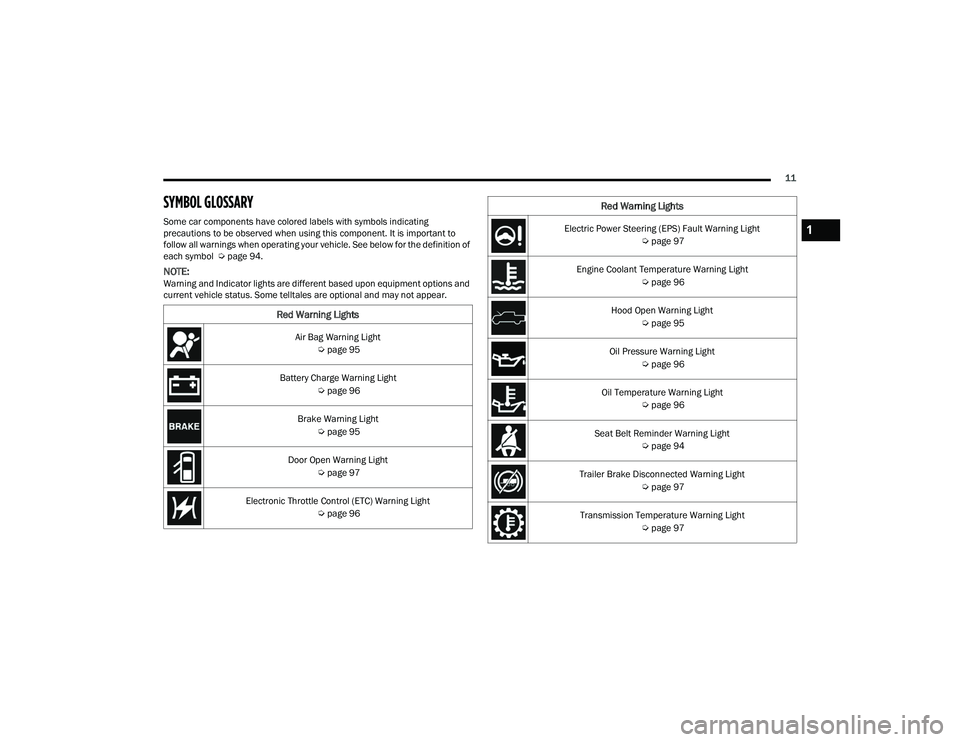
SYMBOL GLOSSARY
Some car components have colored labels with symbols indicating
precautions to be observed when using this component. It is important to
follow all warnings when operating your vehicle. See below for the definition of
each symbol Úpage 94.
NOTE:Warning and Indicator lights are different based upon equipment options and
current vehicle status. Some telltales are optional and may not appear.
Red Warning Lights
Air Bag Warning Light
Úpage 95
Battery Charge Warning Light Úpage 96
Brake Warning Light Úpage 95
Door Open Warning Light Úpage 97
Electronic Throttle Control (ETC) Warning Light Úpage 96
Electric Power Steering (EPS) Fault Warning Light
Úpage 97
Engine Coolant Temperature Warning Light Úpage 96
Hood Open Warning Light Úpage 95
Oil Pressure Warning Light Úpage 96
Oil Temperature Warning Light Úpage 96
Seat Belt Reminder Warning Light Úpage 94
Trailer Brake Disconnected Warning Light Úpage 97
Transmission Temperature Warning Light Úpage 97
Red Warning Lights
1
22_DPF_OM_EN_USC_t.book Page 11
Page 14 of 428
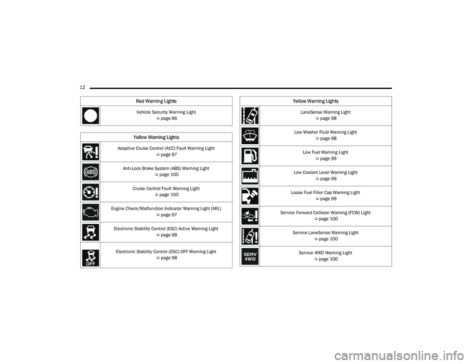
12 Vehicle Security Warning Light Úpage 96
Yellow Warning Lights
Adaptive Cruise Control (ACC) Fault Warning Light
Úpage 97
Anti-Lock Brake System (ABS) Warning Light Úpage 100
Cruise Control Fault Warning Light Úpage 100
Engine Check/Malfunction Indicator Warning Light (MIL) Úpage 97
Electronic Stability Control (ESC) Active Warning Light Úpage 98
Electronic Stability Control (ESC) OFF Warning Light
Úpage 98
Red Warning Lights
LaneSense Warning Light
Úpage 98
Low Washer Fluid Warning Light Úpage 98
Low Fuel Warning Light Úpage 99
Low Coolant Level Warning Light Úpage 99
Loose Fuel Filler Cap Warning Light Úpage 99
Service Forward Collision Warning (FCW) Light Úpage 100
Service LaneSense Warning Light Úpage 100
Service 4WD Warning Light Úpage 100
Yellow Warning Lights
22_DPF_OM_EN_USC_t.book Page 12
Page 15 of 428
13
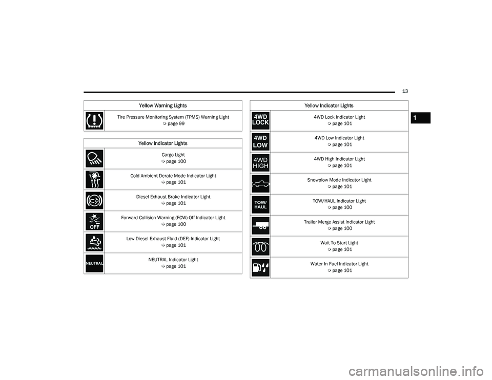
Tire Pressure Monitoring System (TPMS) Warning Light Úpage 99
Yellow Indicator Lights
Cargo Light
Ú page 100
Cold Ambient Derate Mode Indicator Light Úpage 101
Diesel Exhaust Brake Indicator Light Úpage 101
Forward Collision Warning (FCW) Off Indicator Light Úpage 100
Low Diesel Exhaust Fluid (DEF) Indicator Light Úpage 101
NEUTRAL Indicator Light Úpage 101
Yellow Warning Lights
4WD Lock Indicator Light
Úpage 101
4WD Low Indicator Light Úpage 101
4WD High Indicator Light Úpage 101
Snowplow Mode Indicator Light Úpage 101
TOW/HAUL Indicator Light Úpage 100
Trailer Merge Assist Indicator Light Úpage 100
Wait To Start Light Úpage 101
Water In Fuel Indicator Light Úpage 101
Yellow Indicator Lights
1
22_DPF_OM_EN_USC_t.book Page 13
Page 22 of 428
20GETTING TO KNOW YOUR VEHICLE
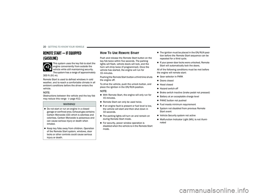
REMOTE START — IF EQUIPPED
(GASOLINE)
This system uses the key fob to start the
engine conveniently from outside the
vehicle while still maintaining security.
The system has a range of approximately
300 ft (91 m).
Remote Start is used to defrost windows in cold
weather, and to reach a comfortable climate in all
ambient conditions before the driver enters the
vehicle.
NOTE:Obstructions between the vehicle and the key fob
may reduce this range Ú page 412.
HOW TO USE REMOTE START
Push and release the Remote Start button on the
key fob twice within five seconds. The parking
lights will flash, vehicle doors will lock, and the
horn will chirp twice (if programmed). Once the
vehicle has started, the engine will run for
15 minutes.
Pushing the Remote Start button a third time shuts
the engine off.
To drive the vehicle, push the unlock button, and
place the ignition in the ON/RUN position.
NOTE:
With Remote Start, the engine will only run for
15 minutes.
Remote Start can only be used twice.
If an engine fault is present or fuel level is low,
the vehicle will start and then shut down in
10 seconds.
The parking lights will turn on and remain on
during Remote Start mode.
For security, power window operation is
disabled when the vehicle is in the Remote Start
mode.
The ignition must be placed in the ON/RUN posi -
tion before the Remote Start sequence can be
repeated for a third cycle.
If your power door locks were unlocked, Remote
Start will automatically lock the doors.
All of the following conditions must be met before
the engine will remote start:
Gear selector in PARK
Doors closed
Hood closed
Hazard switch off
Brake switch inactive (brake pedal not pressed)
Battery at an acceptable charge level
PANIC button not pushed
Fuel meets minimum requirement
System not disabled from previous Remote
Start event
Vehicle Security system not active
Malfunction Indicator Light (MIL) is not illumi -
nated
WARNING!
Do not start or run an engine in a closed
garage or confined area. Exhaust gas contains
Carbon Monoxide (CO) which is odorless and
colorless. Carbon Monoxide is poisonous and
can cause serious injury or death when
inhaled.
Keep key fobs away from children. Operation
of the Remote Start system, windows, door
locks or other controls could cause serious
injury or death.
22_DPF_OM_EN_USC_t.book Page 20
Page 24 of 428
22GETTING TO KNOW YOUR VEHICLE
REMOTE START ABORT MESSAGE
The following messages will display in the
instrument cluster display if the vehicle fails to
remote start or exits Remote Start prematurely:
Remote Start Cancelled — Door Open
Remote Start Cancelled — Hood Open
Remote Start Cancelled — Fuel Low
Remote Start Cancelled — System Fault
Remote Start Disabled — Start Vehicle to Reset
The instrument cluster display message stays
active until the ignition is placed in the ON/RUN
position.
REMOTE START — IF EQUIPPED (DIESEL)
This system uses the key fob to start the
engine conveniently from outside the
vehicle while still maintaining security.
The system has a range of approximately
300 ft (91 m).
Remote Start is used to defrost windows in cold
weather, and to reach a comfortable climate in all
ambient conditions before the driver enters the
vehicle.
NOTE:
Obstructions between the vehicle and the key
fob may reduce this range.
The Remote Start system will wait for the Wait
To Start Light Úpage 101 to extinguish before
cranking the engine. This allows time for the
intake heater to preheat the incoming air, and is
normal operation in cold weather Ú page 412.
HOW TO USE REMOTE START
Push and release the Remote Start button on the
key fob twice within five seconds. The vehicle
doors will lock, the parking lights will flash, and the
horn will chirp twice (if programmed). Then, the
engine will start, and the vehicle will remain in the
Remote Start mode for a 15 minute cycle.
Pushing the Remote Start button a third time shuts
the engine off.
To drive the vehicle, push the unlock button, and
place the ignition in the ON/RUN position.
All of the following conditions must be met before
the engine will remote start:
Gear selector in PARK
Doors closed
Hood closed
Hazard switch off
Brake switch inactive (brake pedal not pressed)
Battery at an acceptable charge level
PANIC button not pushed
Fuel meets minimum requirement
Water In Fuel Indicator Light is not illuminated
Wait To Start Light is not illuminated
Malfunction Indicator Light (MIL) is not illumi -
nated
For additional functions of the Remote Start
system, see Ú page 21
WARNING!
Do not start or run an engine in a closed
garage or confined area. Exhaust gas contains
Carbon Monoxide (CO) which is odorless and
colorless. Carbon Monoxide is poisonous and
can cause serious injury or death when
inhaled.
Keep key fobs away from children. Operation
of the Remote Start system, windows, door
locks or other controls could cause serious
injury or death.
22_DPF_OM_EN_USC_t.book Page 22
Page 33 of 428

GETTING TO KNOW YOUR VEHICLE31
SEATS
Seats are a part of the Occupant Restraint system
of the vehicle.
MANUAL FRONT SEAT ADJUSTMENT
Manual Front Seat Forward/Rearward
Adjustment
Both front seats are adjustable forward or
rearward. The manual seat adjustment handle is
located under the seat cushion at the front edge of
each seat.
Manual Seat Adjustment Bar
While sitting in the seat, pull up on the handle and
slide the seat forward or rearward. Release the bar
once you have reached the desired position. Then,
using body pressure, move forward and rearward
on the seat to be sure that the seat adjusters have
latched.
Manual Front Seat Recline Adjustment
The recline lever is located on the outboard side of
the seat. To recline the seat, lean forward slightly,
lift the lever, lean back to the desired position and
release the lever. To return the seatback to its
normal upright position, lean forward and lift the
lever. Release the lever once the seatback is in the
upright position.
Manual Recline Lever
WARNING!
It is dangerous to ride in a cargo area, inside
or outside of a vehicle. In a collision, people
riding in these areas are more likely to be seri -
ously injured or killed.
Do not allow people to ride in any area of your
vehicle that is not equipped with seats and
seat belts. In a collision, people riding in these
areas are more likely to be seriously injured or
killed.
Be sure everyone in your vehicle is in a seat
and using a seat belt properly.
WARNING!
Adjusting a seat while driving may be
dangerous. Moving a seat while driving could
result in loss of control which could cause a
collision and serious injury or death.
Seats should be adjusted before fastening the
seat belts and while the vehicle is parked.
Serious injury or death could result from a
poorly adjusted seat belt.
WARNING!
Do not stand or lean in front of the seat while
actuating the handle. The seatback may swing
forward and hit you causing injury.
To avoid injury, place your hand on the seat -
back and actuate the handle, then position
the seatback in the desired position.
2
22_DPF_OM_EN_USC_t.book Page 31
Page 42 of 428

40GETTING TO KNOW YOUR VEHICLE
“Slide-On-Rod” Features Of Sun Visor —
If Equipped
The sun visor “Slide-On-Rod” feature allows for
additional flexibility in positioning the sun visor to
block out the sun.
1. Fold down the sun visor.
2. Unclip the visor from the corner clip.
3. Pivot the sun visor toward the side window.
4. Extend the sun visor for additional sun
blockage.
“Slide-On-Rod” Extender
NOTE:The sun visor can also be extended while the sun
visor is against the windshield for additional sun
blockage through the front of the vehicle.
OUTSIDE MIRRORS
To receive maximum benefit, adjust the outside
mirrors to center on the adjacent lane of traffic
with a slight overlap of the view obtained on the
inside mirror.
NOTE:If your vehicle is equipped with puddle lamps
under the outside mirrors, they can be turned off
through the Uconnect system Ú page 191.
POWER MIRRORS — IF EQUIPPED
The controls for the power mirrors are located on
the driver's door trim panel.
Power Mirror Controls
The power mirror controls consist of mirror select
buttons and a four-way mirror control switch.
To adjust a mirror, push either the L (left) or R
(right) button to select the mirror that you want to
adjust.
WARNING!
Vehicles and other objects seen in the
passenger side convex mirror will look smaller
and farther away than they really are. Relying too
much on your passenger side convex mirror
could cause you to collide with another vehicle
or other object. Use your inside mirror when
judging the size or distance of a vehicle seen in
the passenger side convex mirror. Some vehicles
will not have a convex passenger side mirror.
1 — Left Mirror Selection
2 — Mirror Direction Control
3 — Right Mirror Selection
22_DPF_OM_EN_USC_t.book Page 40
Page 47 of 428

GETTING TO KNOW YOUR VEHICLE45
3. Push the programmed HomeLink® button to confirm that the garage door opener motor
operates. If the garage door opener motor
does not operate, repeat the final steps for the
rolling code procedure.
Non-Rolling Code Garage Door Opener Final Steps
1. Push and hold the programmed HomeLink® button and observe the HomeLink® indicator
light. If the HomeLink® indicator light stays
on constantly, programming is complete.
2. Push the programmed HomeLink® button to confirm that the garage door opener motor
operates. If the garage door opener motor
does not operate, repeat the steps from the
beginning.
PROGRAMMING HOMELINK® TO A
M
ISCELLANEOUS DEVICE
The procedure on how to program HomeLink® to a
miscellaneous device follows the same procedure
as programming to a garage door opener
Ú page 44. Be sure to determine if the device has
a rolling code, or non-rolling code before beginning
the programming process.
NOTE:Canadian radio frequency laws require transmitter
signals to time-out (or quit) after several seconds
of transmission, which may not be long enough for
HomeLink® to pick up the signal during
programming. Similar to this Canadian law, some
U.S. gate operators are designed to time-out in the
same manner. The procedure may need to be
performed multiple times to successfully pair the
device to your HomeLink® buttons.
REPROGRAMMING A SINGLE
H
OMELINK® BUTTON
To reprogram a single HomeLink® button that has
been previously trained, without erasing all the
channels, follow the procedure below. Be sure to
determine whether the new device you want to
program the HomeLink® button to has a rolling
code, or non-rolling code.
1. Place the ignition in the ON/RUN position,
without starting the engine.
2. Push and hold the desired HomeLink® button
until the HomeLink® Indicator light begins to
flash after 20 seconds. Do not release the
button.
3. Without releasing the button , proceed with
Step 2 in “Programming HomeLink® To A
Garage Door Opener” Ú page 44, and follow
all remaining steps.
CANADIAN/GATE OPERATOR
P
ROGRAMMING
For programming transmitters in Canada/United
States that require the transmitter signals to
“time-out” after several seconds of transmission.
Canadian radio frequency laws require transmitter
signals to time-out (or quit) after several seconds
of transmission – which may not be long enough
for HomeLink® to pick up the signal during
programming. Similar to this Canadian law, some
U.S. gate operators are designed to time-out in the
same manner.
It may be helpful to unplug the device during the
cycling process to prevent possible overheating of
the garage door or gate motor.
1. Place the ignition in the ON/RUN position.
2. Place the hand-held transmitter 1 to 3 inches
(3 to 8 cm) away from the HomeLink® button
you wish to program while keeping the
HomeLink® indicator light in view.
WARNING!
Your motorized door or gate will open and close
while you are programming the universal trans -
ceiver. Do not program the transceiver if people
or pets are in the path of the door or gate.
Do not run your vehicle in a closed garage or
confined area while programming the trans -
ceiver. Exhaust gas from your vehicle contains
Carbon Monoxide (CO) which is odorless and
colorless. Carbon Monoxide is poisonous
when inhaled and can cause you and others to
be severely injured or killed.
2
22_DPF_OM_EN_USC_t.book Page 45