window RAM CHASSIS CAB 2022 Owners Manual
[x] Cancel search | Manufacturer: RAM, Model Year: 2022, Model line: CHASSIS CAB, Model: RAM CHASSIS CAB 2022Pages: 428, PDF Size: 20.18 MB
Page 5 of 428
3
EXTERIOR LIGHTS.................................................. 47 Headlight Switch...............................................47
Multifunction Lever ..........................................47
Daytime Running Lights (DRLs) ......................48
High/Low Beam Switch....................................48
Automatic High Beam Headlamp Control —
If Equipped........................................................48
Flash-To-Pass....................................................48
Automatic Headlights — If Equipped ..............48
Directional LED Headlamp System —
If Equipped........................................................49
Parking Lights ...................................................49
Headlights On With Wipers ..............................49
Headlight Delay ................................................49
Lights-On Reminder..........................................49
Front Fog Lights — If Equipped .......................50
Turn Signals .....................................................50
Lane Change Assist — If Equipped ..................50
Cargo Lights/Trailer Spotter Lights —
If Equipped........................................................50
Battery Saver ....................................................51
INTERIOR LIGHTS ................................................. 51
Courtesy Lights .................................................51
Illuminated Entry .............................................52
WINDSHIELD WIPERS AND WASHERS .............. 53
Windshield Wiper Operation ...........................53
Rain Sensing Wipers — If Equipped ...............54 CLIMATE CONTROLS .............................................54
Automatic Climate Control Descriptions And
Functions ..........................................................54
Manual Climate Control Descriptions And
Functions ..........................................................58
Automatic Temperature Control (ATC) ............60
Climate Voice Recognition — If Equipped .......60
Operating Tips .................................................60
INTERIOR STORAGE AND EQUIPMENT ............... 61
Storage..............................................................61
USB/AUX Control ..............................................66
Electrical Power Outlets ...................................68
Power Inverter — If Equipped ..........................69
Wireless Charging Pad — If Equipped ............70
WINDOWS ..............................................................71
Power Windows — If Equipped ........................71
Automatic Window Features — If Equipped....71
Reset Auto-Up ..................................................72
Window Lockout Switch — If Equipped ...........72
Power Sliding Rear Window — If Equipped ....72
Manual Sliding Rear Window — If Equipped...72
Wind Buffeting .................................................72
HOOD .......................................................................73
To Open The Hood ...........................................73
To Close The Hood ...........................................73
GETTING TO KNOW YOUR
INSTRUMENT PANEL
BASE / MIDLINE INSTRUMENT CLUSTER —
GASOLINE ............................................................... 74Base / Midline Instrument Cluster
Descriptions...................................................... 75
PREMIUM INSTRUMENT CLUSTER —
GASOLINE ............................................................... 76
Premium Instrument Cluster Descriptions ..... 77
BASE / MIDLINE INSTRUMENT CLUSTER —
DIESEL .................................................................... 78
Diesel Instrument Cluster ............................... 79
PREMIUM INSTRUMENT CLUSTER — DIESEL ... 80
Diesel Instrument Cluster ............................... 81
INSTRUMENT CLUSTER DISPLAY ........................ 81
Instrument Cluster Display And Controls........ 82
Oil Life Reset ................................................... 82
Display Menu Items ......................................... 83
Diesel Messages And Warnings ...................... 90
Battery Saver On/Battery Saver Mode
Message — Electrical Load Reduction
Actions — If Equipped ...................................... 93
WARNING LIGHTS AND MESSAGES ................... 94
Red Warning Lights ..........................................94
Yellow Warning Lights ...................................... 97
Yellow Indicator Lights .................................. 100 Green Indicator Lights .................................. 101White Indicator Lights ................................... 102
Blue Indicator Lights ..................................... 103
22_DPF_OM_EN_USC_t.book Page 3
Page 21 of 428
GETTING TO KNOW YOUR VEHICLE19
(Continued)
The push button ignition can be placed in the
following modes:
OFF
The engine is stopped.
Some electrical devices (e.g. power locks,
alarm, etc.) are still available.
ACC
Engine is not started.
Some electrical devices are available (e.g.
power windows, etc.).
RUN
Driving position.
All electrical devices are available (e.g. climate
controls, heated seats, etc.).
START
The engine will start.
In case the ignition switch does not change with
the push of a button, the key fob may have a low or
depleted battery. In this situation, a back up
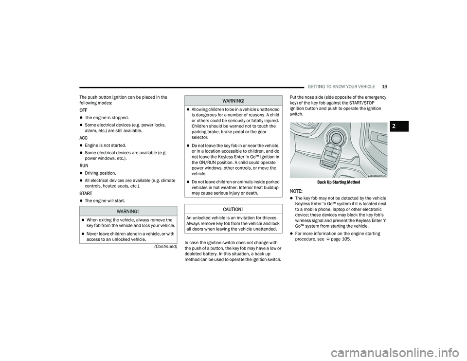
method can be used to operate the ignition switch. Put the nose side (side opposite of the emergency
key) of the key fob against the START/STOP
ignition button and push to operate the ignition
switch.
Back Up Starting Method
NOTE:
The key fob may not be detected by the vehicle
Keyless Enter ‘n Go™ system if it is located next
to a mobile phone, laptop or other electronic
device; these devices may block the key fob’s
wireless signal and prevent the Keyless Enter ‘n
Go™ system from starting the vehicle.
For more information on the engine starting
procedure, see Ú page 105.
WARNING!
When exiting the vehicle, always remove the
key fob from the vehicle and lock your vehicle.
Never leave children alone in a vehicle, or with
access to an unlocked vehicle.
Allowing children to be in a vehicle unattended
is dangerous for a number of reasons. A child
or others could be seriously or fatally injured.
Children should be warned not to touch the
parking brake, brake pedal or the gear
selector.
Do not leave the key fob in or near the vehicle,
or in a location accessible to children, and do
not leave the Keyless Enter ‘n Go™ Ignition in
the ON/RUN position. A child could operate
power windows, other controls, or move the
vehicle.
Do not leave children or animals inside parked
vehicles in hot weather. Interior heat buildup
may cause serious injury or death.
CAUTION!
An unlocked vehicle is an invitation for thieves.
Always remove key fob from the vehicle and lock
all doors when leaving the vehicle unattended.
WARNING!
2
22_DPF_OM_EN_USC_t.book Page 19
Page 22 of 428
20GETTING TO KNOW YOUR VEHICLE
REMOTE START — IF EQUIPPED
(GASOLINE)
This system uses the key fob to start the
engine conveniently from outside the
vehicle while still maintaining security.
The system has a range of approximately
300 ft (91 m).
Remote Start is used to defrost windows in cold
weather, and to reach a comfortable climate in all
ambient conditions before the driver enters the
vehicle.
NOTE:Obstructions between the vehicle and the key fob
may reduce this range Ú page 412.
HOW TO USE REMOTE START
Push and release the Remote Start button on the
key fob twice within five seconds. The parking
lights will flash, vehicle doors will lock, and the
horn will chirp twice (if programmed). Once the
vehicle has started, the engine will run for
15 minutes.
Pushing the Remote Start button a third time shuts
the engine off.
To drive the vehicle, push the unlock button, and
place the ignition in the ON/RUN position.
NOTE:
With Remote Start, the engine will only run for
15 minutes.
Remote Start can only be used twice.
If an engine fault is present or fuel level is low,
the vehicle will start and then shut down in
10 seconds.
The parking lights will turn on and remain on
during Remote Start mode.
For security, power window operation is
disabled when the vehicle is in the Remote Start
mode.
The ignition must be placed in the ON/RUN posi -
tion before the Remote Start sequence can be
repeated for a third cycle.
If your power door locks were unlocked, Remote
Start will automatically lock the doors.
All of the following conditions must be met before
the engine will remote start:
Gear selector in PARK
Doors closed
Hood closed
Hazard switch off
Brake switch inactive (brake pedal not pressed)
Battery at an acceptable charge level
PANIC button not pushed
Fuel meets minimum requirement
System not disabled from previous Remote
Start event
Vehicle Security system not active
Malfunction Indicator Light (MIL) is not illumi -
nated
WARNING!
Do not start or run an engine in a closed
garage or confined area. Exhaust gas contains
Carbon Monoxide (CO) which is odorless and
colorless. Carbon Monoxide is poisonous and
can cause serious injury or death when
inhaled.
Keep key fobs away from children. Operation
of the Remote Start system, windows, door
locks or other controls could cause serious
injury or death.
22_DPF_OM_EN_USC_t.book Page 20
Page 24 of 428
22GETTING TO KNOW YOUR VEHICLE
REMOTE START ABORT MESSAGE
The following messages will display in the
instrument cluster display if the vehicle fails to
remote start or exits Remote Start prematurely:
Remote Start Cancelled — Door Open
Remote Start Cancelled — Hood Open
Remote Start Cancelled — Fuel Low
Remote Start Cancelled — System Fault
Remote Start Disabled — Start Vehicle to Reset
The instrument cluster display message stays
active until the ignition is placed in the ON/RUN
position.
REMOTE START — IF EQUIPPED (DIESEL)
This system uses the key fob to start the
engine conveniently from outside the
vehicle while still maintaining security.
The system has a range of approximately
300 ft (91 m).
Remote Start is used to defrost windows in cold
weather, and to reach a comfortable climate in all
ambient conditions before the driver enters the
vehicle.
NOTE:
Obstructions between the vehicle and the key
fob may reduce this range.
The Remote Start system will wait for the Wait
To Start Light Úpage 101 to extinguish before
cranking the engine. This allows time for the
intake heater to preheat the incoming air, and is
normal operation in cold weather Ú page 412.
HOW TO USE REMOTE START
Push and release the Remote Start button on the
key fob twice within five seconds. The vehicle
doors will lock, the parking lights will flash, and the
horn will chirp twice (if programmed). Then, the
engine will start, and the vehicle will remain in the
Remote Start mode for a 15 minute cycle.
Pushing the Remote Start button a third time shuts
the engine off.
To drive the vehicle, push the unlock button, and
place the ignition in the ON/RUN position.
All of the following conditions must be met before
the engine will remote start:
Gear selector in PARK
Doors closed
Hood closed
Hazard switch off
Brake switch inactive (brake pedal not pressed)
Battery at an acceptable charge level
PANIC button not pushed
Fuel meets minimum requirement
Water In Fuel Indicator Light is not illuminated
Wait To Start Light is not illuminated
Malfunction Indicator Light (MIL) is not illumi -
nated
For additional functions of the Remote Start
system, see Ú page 21
WARNING!
Do not start or run an engine in a closed
garage or confined area. Exhaust gas contains
Carbon Monoxide (CO) which is odorless and
colorless. Carbon Monoxide is poisonous and
can cause serious injury or death when
inhaled.
Keep key fobs away from children. Operation
of the Remote Start system, windows, door
locks or other controls could cause serious
injury or death.
22_DPF_OM_EN_USC_t.book Page 22
Page 26 of 428

24GETTING TO KNOW YOUR VEHICLE
(Continued)
DOORS
MANUAL DOOR LOCKS
The power door locks can be manually locked from
inside the vehicle by using the door lock knob. To
lock each door, push the door lock knob on each
door trim panel downward. To unlock the front
doors, pull the inside door handle to the first
detent. To unlock the rear doors, pull the door lock
knob on the door trim panel upward. If the lock
knob is down when the door is closed, the door will
lock. Therefore, make sure the key fob is not inside
the vehicle before closing the door.
Door Lock Knob
POWER DOOR LOCKS — IF EQUIPPED
The power door lock switches are located on each
front door panel. Push the switch to lock or unlock
the doors.
Power Door Lock Switches
WARNING!
Do not leave children or animals inside parked
vehicles in hot weather. Interior heat buildup
may cause serious injury or death.
For personal security and safety in the event
of an collision, lock the vehicle doors as you
drive as well as when you park and leave the
vehicle.
Before exiting a vehicle, always shift the auto -
matic transmission into PARK, apply the
parking brake, turn the vehicle OFF, remove
the key fobs from vehicle, and lock all doors.
and lock your vehicle.
Never leave children alone in a vehicle, or with
access to an unlocked vehicle. Leaving chil -
dren in a vehicle unattended is dangerous for
a number of reasons. A child or others could
be seriously or fatally injured. Children should
be warned not to touch the parking brake,
brake pedal or the gear selector.
Allowing children to be in a vehicle unattended
is dangerous for a number of reasons. A child
or others could be seriously or fatally injured.
Children should be warned not to touch the
parking brake, brake pedal or the gear
selector.
Do not leave the key fob in or near the vehicle,
or in a location accessible to children, and do
not leave the Keyless Enter ‘n Go™ Ignition in
the ACC or ON/RUN position. A child could
operate power windows, other controls, or
move the vehicle.
WARNING!
22_DPF_OM_EN_USC_t.book Page 24
Page 29 of 428

GETTING TO KNOW YOUR VEHICLE27
CHILD-PROTECTION DOOR LOCK —
I
F EQUIPPED
To provide a safer environment for children riding
in the rear seat, the rear doors (if equipped) of your
vehicle have the Child-Protection Door Lock
system.
To use the system, open each rear door, use a flat
blade screwdriver (or emergency key) and rotate
the dial to engage and disengage the
Child-Protection locks. When the system on a door
is engaged, that door can only be opened by using
the outside door handle even if the inside door lock
is in the unlocked position.
Child Lock Control
NOTE:
After setting the Child-Protection Door Lock
system, always test the door from the inside to
make certain it is in the desired position.
For emergency exit with the system engaged,
move the door lock switch to the unlock posi -
tion, roll down the window, and open the door
with the outside door handle.
STEERING WHEEL
TILT STEERING COLUMN
This feature allows you to tilt the steering column
upward or downward. The tilt lever is located on
the steering column, below the multifunction lever.
Pull the lever toward the steering wheel to unlock
the steering column. With one hand firmly on the
steering wheel, move the steering column up or
down, as desired. Release the lever to lock the
steering column firmly in place.
Tilt Steering Lever
WARNING!
Avoid trapping anyone in the vehicle in a
collision. Remember that the rear doors cannot
be opened from the inside door handle when the
Child Protection Door Locks are engaged.
WARNING!
Do not adjust the steering column while driving.
Adjusting the steering column while driving or
driving with the steering column unlocked, could
cause the driver to lose control of the vehicle.
Failure to follow this warning may result in
serious injury or death.
2
22_DPF_OM_EN_USC_t.book Page 27
Page 40 of 428
38GETTING TO KNOW YOUR VEHICLE
MIRRORS
INSIDE REARVIEW MIRROR
Manual Mirror — If Equipped
The mirror head can be adjusted up, down, left,
and right. The mirror should be adjusted to center
on the view through the rear window.
Headlight glare from vehicles behind you can be
reduced by moving the small control under the
mirror to the night position (toward the rear of the
vehicle). The mirror should be adjusted while set in
the day position (toward the windshield).
Adjusting Rearview Mirror
Automatic Dimming Mirror — If Equipped
The mirror head can be adjusted up, down, left,
and right. The mirror should be adjusted to center
on the view through the rear window. This mirror automatically adjusts for headlight
glare from vehicles behind you.
NOTE:The Automatic Dimming feature is disabled when
the vehicle is in REVERSE to improve rear view
viewing.
The Automatic Dimming feature can be turned on
or off through the touchscreen.
Automatic Dimming Mirror
Automatic Dimming Mirror With Rear View
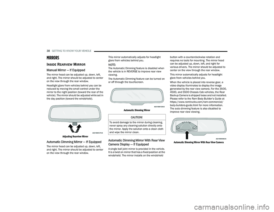
Camera Display — If Equipped
A single ball joint mirror is provided in the vehicle.
It is a twist on mirror that has a fixed position at the
windshield. The mirror installs on the windshield button with a counterclockwise rotation and
requires no tools for mounting. The mirror head
can be adjusted up, down, left, and right for
various drivers. The mirror should be adjusted to
center on the view through the rear window.
This mirror automatically adjusts for headlight
glare from vehicles behind you.
When the vehicle is placed into reverse gear, a
video display illuminates to display the image
generated by the rear view camera. For the 3500,
4500, and 5500 Chassis Cab vehicles, the Rear
Backup Camera is shipped loose and not installed.
Please refer to the Ram Body Builder’s Guide at
https://www.ramtrucks.com/ram-commercial/
body-builders-guide.html for more information.
The auto dimming feature is also disabled to
improve rear view viewing.
Automatic Dimming Mirror With Rear View Camera
CAUTION!
To avoid damage to the mirror during cleaning,
never spray any cleaning solution directly onto
the mirror. Apply the solution onto a clean cloth
and wipe the mirror clean.
22_DPF_OM_EN_USC_t.book Page 38
Page 42 of 428

40GETTING TO KNOW YOUR VEHICLE
“Slide-On-Rod” Features Of Sun Visor —
If Equipped
The sun visor “Slide-On-Rod” feature allows for
additional flexibility in positioning the sun visor to
block out the sun.
1. Fold down the sun visor.
2. Unclip the visor from the corner clip.
3. Pivot the sun visor toward the side window.
4. Extend the sun visor for additional sun
blockage.
“Slide-On-Rod” Extender
NOTE:The sun visor can also be extended while the sun
visor is against the windshield for additional sun
blockage through the front of the vehicle.
OUTSIDE MIRRORS
To receive maximum benefit, adjust the outside
mirrors to center on the adjacent lane of traffic
with a slight overlap of the view obtained on the
inside mirror.
NOTE:If your vehicle is equipped with puddle lamps
under the outside mirrors, they can be turned off
through the Uconnect system Ú page 191.
POWER MIRRORS — IF EQUIPPED
The controls for the power mirrors are located on
the driver's door trim panel.
Power Mirror Controls
The power mirror controls consist of mirror select
buttons and a four-way mirror control switch.
To adjust a mirror, push either the L (left) or R
(right) button to select the mirror that you want to
adjust.
WARNING!
Vehicles and other objects seen in the
passenger side convex mirror will look smaller
and farther away than they really are. Relying too
much on your passenger side convex mirror
could cause you to collide with another vehicle
or other object. Use your inside mirror when
judging the size or distance of a vehicle seen in
the passenger side convex mirror. Some vehicles
will not have a convex passenger side mirror.
1 — Left Mirror Selection
2 — Mirror Direction Control
3 — Right Mirror Selection
22_DPF_OM_EN_USC_t.book Page 40
Page 44 of 428

42GETTING TO KNOW YOUR VEHICLE
To return the control to the large mirror, push the
Power Convex Mirror Switch a second time.
Trailer Tow Power Convex Mirror
NOTE:If the Power Convex Mirror Switch is not pushed a
second time, the switch will automatically default
back to the larger portion of the outside mirrors
after a period of time.
TRAILER TOWING MIRRORS
These mirrors are designed with an adjustable
mirror head to provide a greater vision range when
towing extra-wide loads. To change position
inboard or outboard, the mirror head should be
rotated (flipped in or out).
Trailer Towing Position
NOTE:Fold the trailer towing mirrors rearward prior to
entering an automated car wash.
A small blindspot mirror is located next to the main
mirror and can be adjusted manually.
Blindspot Mirror
HEATED MIRRORS — IF EQUIPPED
These mirrors are heated to melt frost or
ice. This feature will be activated
whenever you turn on the rear window
defroster (if equipped) Ú page 54.
TILT SIDE MIRRORS IN REVERSE —
I
F EQUIPPED
This feature provides automatic outside mirror
positioning which will assist with the driver’s
ground visibility. The outside mirrors will move
slightly downward from the present position when
the vehicle is shifted into REVERSE. The outside
mirrors will then return to the original position
when the vehicle is shifted out of REVERSE. If the
vehicle is equipped with Driver Memory Settings,
this feature will be linked to the programmable
settings.
NOTE:The Tilt Side Mirrors In Reverse feature can be
turned on and off using the Uconnect system
Ú page 191.
22_DPF_OM_EN_USC_t.book Page 42
Page 57 of 428

GETTING TO KNOW YOUR VEHICLE55
Uconnect 5 NAV With 12–inch Display Automatic Temperature Controls
NOTE:Icons and descriptions can vary based upon
vehicle equipment.
MAX A/C Button
Press and release the MAX A/C button on
the touchscreen to change the current
setting to the coldest output of air. The
MAX A/C indicator illuminates when MAX
A/C is on. Pressing the button again will cause the
MAX A/C operation to exit. Pressing other settings
will also cause the MAX A/C to exit.
NOTE:
MAX A/C sets the control for maximum cooling
performance.
The MAX A/C button is only available on the
touchscreen.
A/C Button
Press and release this button on the
touchscreen, or push the button on the
faceplate to change the current setting.
The A/C indicator illuminates when A/C is
on.
Recirculation Button
Press and release this button on the
touchscreen, or push the button on the
faceplate, to change the system between
Recirculation mode and outside air
mode. The Recirculation indicator and the A/C
indicator illuminate when the Recirculation button
is pressed. Recirculation can be used when
outside conditions, such as smoke, odors, dust, or
high humidity are present. Recirculation can be
used in all modes. Recirculation may be
unavailable (button on the touchscreen greyed
out) if conditions exist that could create fogging on
the inside of the windshield. The A/C can be
deselected manually without disturbing the mode
control selection. Continuous use of the
Recirculation mode may make the inside air stuffy
and window fogging may occur. Extended use of
this mode is not recommended. Recirculation
mode may automatically adjust to optimize
customer experience for warming, cooling,
dehumidification, etc. In cold weather, use of Recirculation mode may
lead to excessive window fogging. The
Recirculation feature may be unavailable if
conditions exist that could create fogging on the
inside of the windshield.
Auto Button
Set your desired temperature and press
AUTO. AUTO will achieve and maintain
your desired temperature by
automatically adjusting the blower speed
and air distribution. A/C may be active during AUTO
operation to improve performance. AUTO mode is
highly recommended for efficiency.
You can turn AUTO on in one of two ways:
Press and release this button on the touchscreen.
Push the button on the faceplate.
Toggling this function will cause the system to
switch between manual mode and automatic
mode Ú page 60.
Front Defrost Button
Press and release the Front Defrost
button on the touchscreen, or push and
release the button on the faceplate, to
change the current airflow setting to
Defrost mode. The Front Defrost indicator
illuminates when Front Defrost is on. Air comes
from the windshield and side window demist
outlets. When the defrost button is selected, the
2
22_DPF_OM_EN_USC_t.book Page 55