check engine light RAM CHASSIS CAB 2022 Owners Manual
[x] Cancel search | Manufacturer: RAM, Model Year: 2022, Model line: CHASSIS CAB, Model: RAM CHASSIS CAB 2022Pages: 428, PDF Size: 20.18 MB
Page 8 of 428
6
CONNECTED SERVICES FAQS ........................... 247 Connected Services SOS FAQs —
If Equipped .................................................... 248
Connected Services Remote Door Lock/
Unlock FAQs .................................................. 248
Connected Services Roadside Assistance
FAQs .............................................................. 248
Connected Services Send & Go FAQs —
If Equipped .................................................... 248
Connected Services Vehicle Finder FAQs ... 249
Connected Services Stolen Vehicle
Assistance FAQs — If Equipped ................... 249
Connected Services Remote Vehicle Start
FAQs .............................................................. 249
Connected Services Remote Horn & Lights
FAQs ............................................................... 250
Connected Services Account FAQs —
If Equipped..................................................... 250
Data Collection & Privacy.............................. 252
RADIO OPERATION AND MOBILE PHONES...... 252
Regulatory And Safety Information .............. 252
OFF-ROAD PAGES — IF EQUIPPED .................... 253
Off-Road Pages Status Bar ........................... 254
Vehicle Dynamics .......................................... 255
Accessory Gauge ........................................... 256Pitch & Roll .................................................... 257
Suspension .................................................... 258
Forward Facing Camera ................................ 258
SAFETY
SAFETY FEATURES .............................................. 259
Anti-Lock Brake System (ABS) ..................... 259
Electronic Brake Control (EBC) System ...... 260
AUXILIARY DRIVING SYSTEMS.......................... 266
Forward Collision Warning (FCW) With
Mitigation — If Equipped ............................... 266
Tire Pressure Monitoring System (TPMS) .... 268
OCCUPANT RESTRAINT SYSTEMS ................... 275
Occupant Restraint Systems Features ....... 275
Important Safety Precautions ...................... 276Seat Belt Systems ........................................ 276Supplemental Restraint Systems (SRS) ...... 284Child Restraints ............................................. 291
SAFETY TIPS ........................................................ 307
Transporting Passengers .............................. 307Transporting Pets .......................................... 307
Safety Checks You Should Make Inside
The Vehicle ................................................... 307
Periodic Safety Checks You Should Make
Outside The Vehicle ...................................... 309
Exhaust Gas .................................................. 309
Carbon Monoxide Warnings ......................... 310
IN CASE OF EMERGENCY
HAZARD WARNING FLASHERS ......................... 311
ASSIST AND SOS SYSTEM — IF EQUIPPED ...... 312
JACKING AND TIRE CHANGING ........................ 315 4500/5500 Models...................................... 315
Preparations For Jacking .............................. 316
Jacking Instructions 4500 And 5500
Series ............................................................. 316
To Stow The Flat Or Spare — If Equipped ... 318Hub Caps/Wheel Covers — If Equipped....... 318
JUMP STARTING ................................................. 319
Preparations For Jump Start ........................ 320Jump Starting Procedure .............................. 320
IF YOUR ENGINE OVERHEATS ........................... 322
GEAR SELECTOR OVERRIDE .............................. 322
6–Speed Transmission ................................ 322
MANUAL PARK RELEASE ................................... 323
8–Speed Transmission................................. 323
FREEING A STUCK VEHICLE .............................. 324
TOWING A DISABLED VEHICLE .......................... 325
Two-Wheel Drive Models .............................. 326
Four-Wheel Drive Models ............................. 326Emergency Tow Hooks — If Equipped .......... 327
ENHANCED ACCIDENT RESPONSE SYSTEM
(EARS) .................................................................. 327
EVENT DATA RECORDER (EDR) ......................... 327
22_DPF_OM_EN_USC_t.book Page 6
Page 14 of 428
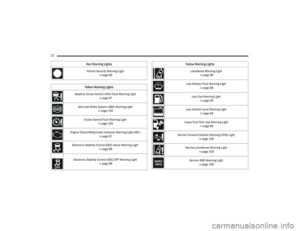
12 Vehicle Security Warning Light Úpage 96
Yellow Warning Lights
Adaptive Cruise Control (ACC) Fault Warning Light
Úpage 97
Anti-Lock Brake System (ABS) Warning Light Úpage 100
Cruise Control Fault Warning Light Úpage 100
Engine Check/Malfunction Indicator Warning Light (MIL) Úpage 97
Electronic Stability Control (ESC) Active Warning Light Úpage 98
Electronic Stability Control (ESC) OFF Warning Light
Úpage 98
Red Warning Lights
LaneSense Warning Light
Úpage 98
Low Washer Fluid Warning Light Úpage 98
Low Fuel Warning Light Úpage 99
Low Coolant Level Warning Light Úpage 99
Loose Fuel Filler Cap Warning Light Úpage 99
Service Forward Collision Warning (FCW) Light Úpage 100
Service LaneSense Warning Light Úpage 100
Service 4WD Warning Light Úpage 100
Yellow Warning Lights
22_DPF_OM_EN_USC_t.book Page 12
Page 18 of 428
16GETTING TO KNOW YOUR VEHICLE
Key Left Vehicle Feature
If a valid key fob is no longer detected inside the
vehicle while the vehicle’s ignition system is in the
ON/RUN or START position, the message “Key Left
Vehicle” will be shown in the instrument cluster
display along with an interior chime. An exterior
audible and visual alert will also be activated to
warn the driver.
The vehicle’s horn will rapidly chirp three times
along with a single flash of the vehicle’s exterior
lights.
NOTE:
The doors have to be open and then closed in
order for the vehicle to check for the presence of
a key fob; the Key Left Vehicle feature will not
activate until all of the doors are closed.
These alerts will not be activated in situations
where the vehicle’s engine is left running with
the key fob inside.
Replacing The Battery In The Key Fob
The replacement battery model is one CR2032
battery.
NOTE:
Customers are recommended to use a battery
obtained from Mopar®. Aftermarket coin
battery dimensions may not meet the original
OEM coin battery dimensions.
Perchlorate Material — special handling may
apply. See www.dtsc.ca.gov/hazardouswaste/
perchlorate for further information.
Do not touch the battery terminals that are on
the back housing or the printed circuit board.
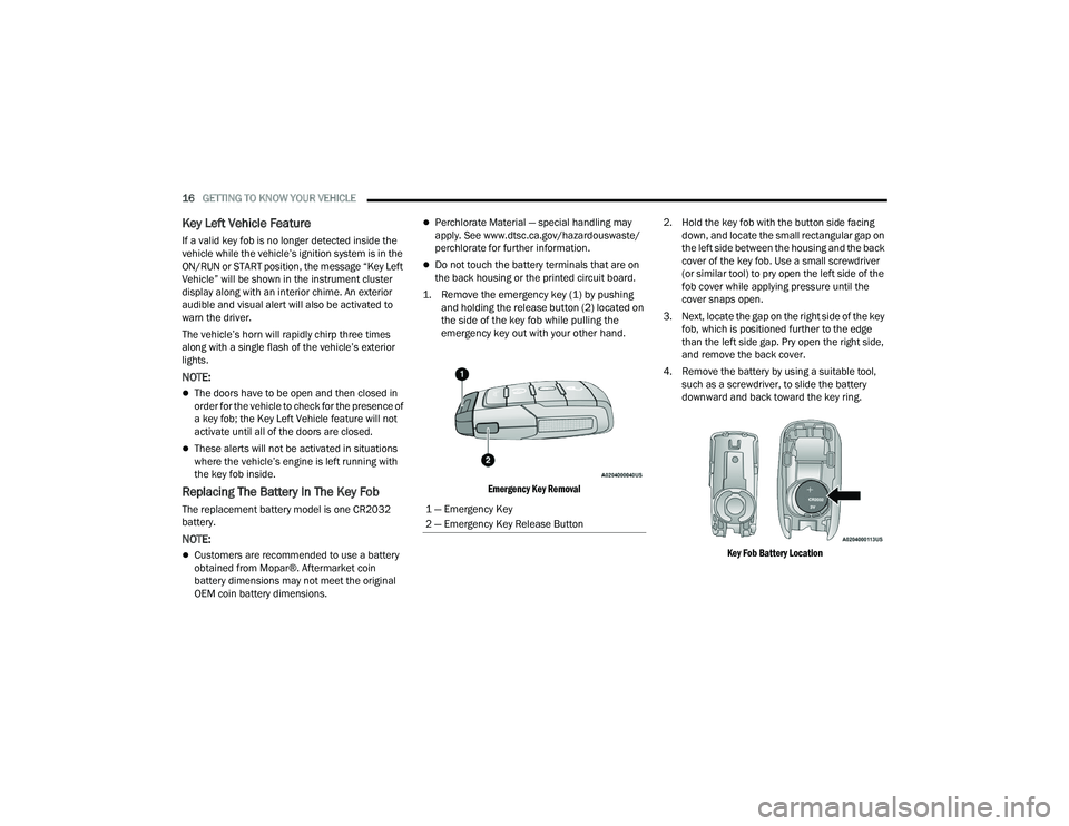
1. Remove the emergency key (1) by pushing and holding the release button (2) located on
the side of the key fob while pulling the
emergency key out with your other hand.
Emergency Key Removal
2. Hold the key fob with the button side facing
down, and locate the small rectangular gap on
the left side between the housing and the back
cover of the key fob. Use a small screwdriver
(or similar tool) to pry open the left side of the
fob cover while applying pressure until the
cover snaps open.
3. Next, locate the gap on the right side of the key fob, which is positioned further to the edge
than the left side gap. Pry open the right side,
and remove the back cover.
4. Remove the battery by using a suitable tool, such as a screwdriver, to slide the battery
downward and back toward the key ring.
Key Fob Battery Location
1 — Emergency Key
2 — Emergency Key Release Button
22_DPF_OM_EN_USC_t.book Page 16
Page 20 of 428
18GETTING TO KNOW YOUR VEHICLE
NOTE:
When having the Sentry Key Immobilizer system
serviced, bring all vehicle keys with you to an
authorized dealer.
Keys must be ordered to the correct key cut to
match the vehicle locks.
SENTRY KEY
The Sentry Key Immobilizer system prevents
unauthorized vehicle operation by disabling the
engine. The system does not need to be armed or
activated. Operation is automatic, regardless of
whether the vehicle is locked or unlocked.
The system uses a key fob, keyless push button
ignition and a Radio Frequency (RF) receiver to
prevent unauthorized vehicle operation. Therefore,
only key fobs that are programmed to the vehicle
can be used to start and operate the vehicle. The
system cannot reprogram a key fob obtained from
another vehicle.
After placing the ignition in the ON/RUN position,
the Vehicle Security Light will turn on for three
seconds for a bulb check. If the light remains on
after the bulb check, it indicates that there is a
problem with the electronics. In addition, if the light
begins to flash after the bulb check, it indicates
that someone attempted to start the engine with
an invalid key fob. In the event that a valid key fob
is used to start the engine but there is an issue with the vehicle electronics, the engine will start
and shut off after two seconds.
If the Vehicle Security Light turns on during normal
vehicle operation (vehicle running for longer than
10 seconds), it indicates that there is a fault in the
electronics. Should this occur, have the vehicle
serviced as soon as possible by an authorized
dealer.
All of the key fobs provided with your new vehicle
have been programmed to the vehicle electronics
Ú
page 412.
IGNITION SWITCH
KEYLESS ENTER ‘N GO™ IGNITION
This feature allows the driver to operate the
ignition switch with the push of a button as long as
the Remote Keyless Entry key fob is in the
passenger compartment.
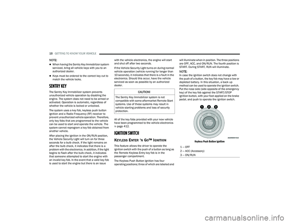
The Keyless Push Button Ignition has four
operating positions; three of which are labeled and will illuminate when in position. The three positions
are OFF, ACC, and ON/RUN. The fourth position is
START. During START, RUN will illuminate.
NOTE:In case the ignition switch does not change with
the push of a button, the key fob may have a low or
depleted battery. In this situation, a back up
method can be used to operate the ignition switch.
Put the nose side (side opposite of the emergency
key) of the key fob against the START/STOP
ignition button, with your foot applied on the brake
pedal, and push to operate the ignition switch.
Keyless Push Button Ignition
CAUTION!
The Sentry Key Immobilizer system is not
compatible with some aftermarket Remote Start
systems. Use of these systems may result in
vehicle starting problems and loss of security
protection.
1 — OFF
2 — ACC (Accessory)
3 — ON/RUN
22_DPF_OM_EN_USC_t.book Page 18
Page 96 of 428
94GETTING TO KNOW YOUR INSTRUMENT PANEL
Loss of the battery charge may indicate one or
more of the following conditions:
The charging system cannot deliver enough
electrical power to the vehicle system because
the electrical loads are larger than the capability
of charging system. The charging system is still
functioning properly.
Turning on all possible vehicle electrical loads
(e.g. HVAC to max settings, exterior and interior
lights, overloaded power outlets +12 Volts,
115 Volt AC, USB ports) during certain driving
conditions (city driving, towing, frequent stop -
ping).
Installing options like additional lights, upfitter
electrical accessories, audio systems, alarms
and similar devices.
Unusual driving cycles (short trips separated by
long parking periods).
The vehicle was parked for an extended period
of time (weeks, months).
The battery was recently replaced and was not
charged completely.
The battery was discharged by an electrical load
left on when the vehicle was parked.
The battery was used for an extended period
with the engine not running to supply radio,
lights, chargers, +12 Volt portable appliances
like vacuum cleaners, game consoles and
similar devices. What to do when an electrical load reduction
action message is present (“Battery Saver On” or
“Battery Saver Mode”)
During a trip:
Reduce power to unnecessary loads if possible:
Turn off redundant lights (interior or exte
-
rior).
Check what may be plugged in to power
outlets +12 Volts, 115 Volt AC, USB ports.
Check HVAC settings (blower, temperature).
Check the audio settings (volume).
After a trip:
Check if any aftermarket equipment was
installed (additional lights, upfitter electrical
accessories, audio systems, alarms) and review
specifications if any (load and Ignition Off Draw
currents).
Evaluate the latest driving cycles (distance,
driving time and parking time).
The vehicle should have service performed if
the message is still present during consecutive
trips and the evaluation of the vehicle and
driving pattern did not help to identify the cause.
WARNING LIGHTS AND MESSAGES
The warning/indicator lights will illuminate in the
instrument panel together with a dedicated
message and/or acoustic signal when applicable.
These indications are indicative and precautionary
and as such must not be considered as exhaustive.
Always refer to the information in this chapter in
the event of a failure indication. All active telltales
will display first if applicable. The system check
menu may appear different based upon
equipment options and current vehicle status.
Some telltales are optional and may not appear.
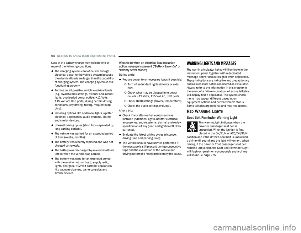
RED WARNING LIGHTS
Seat Belt Reminder Warning Light
This warning light indicates when the
driver or passenger seat belt is
unbuckled. When the ignition is first
placed in the ON/RUN or ACC/ON/RUN
position and if the driver’s seat belt is unbuckled,
a chime will sound and the light will turn on. When
driving, if the driver or front passenger seat belt
remains unbuckled, the Seat Belt Reminder Light
will flash or remain on continuously and a chime
will sound Ú page 275.
22_DPF_OM_EN_USC_t.book Page 94
Page 98 of 428
96GETTING TO KNOW YOUR INSTRUMENT PANEL
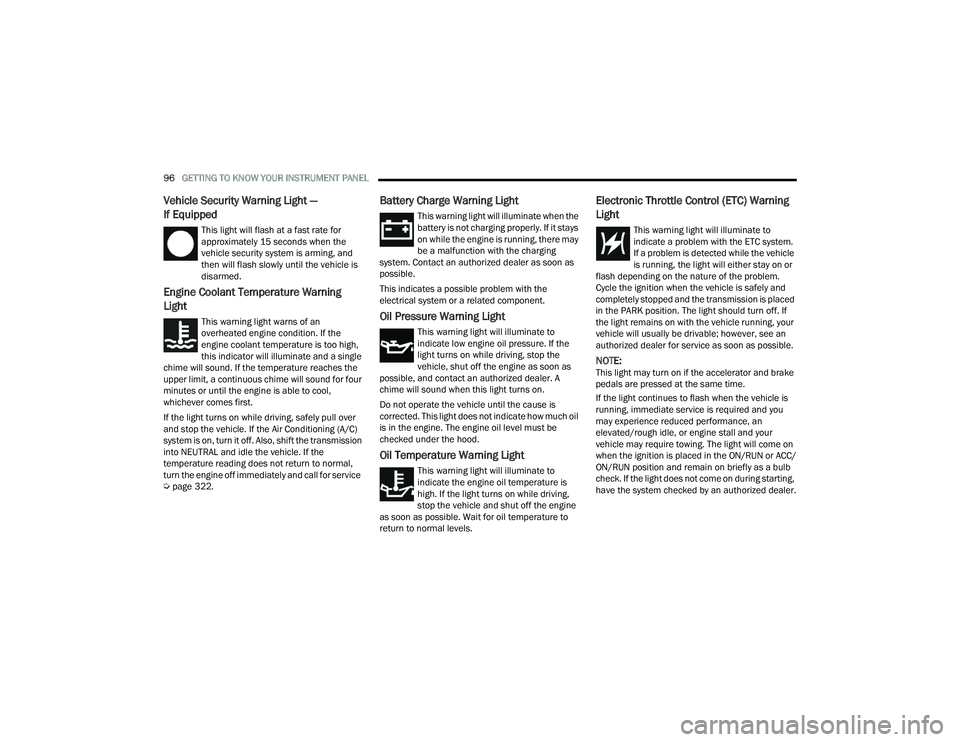
Vehicle Security Warning Light —
If Equipped
This light will flash at a fast rate for
approximately 15 seconds when the
vehicle security system is arming, and
then will flash slowly until the vehicle is
disarmed.
Engine Coolant Temperature Warning
Light
This warning light warns of an
overheated engine condition. If the
engine coolant temperature is too high,
this indicator will illuminate and a single
chime will sound. If the temperature reaches the
upper limit, a continuous chime will sound for four
minutes or until the engine is able to cool,
whichever comes first.
If the light turns on while driving, safely pull over
and stop the vehicle. If the Air Conditioning (A/C)
system is on, turn it off. Also, shift the transmission
into NEUTRAL and idle the vehicle. If the
temperature reading does not return to normal,
turn the engine off immediately and call for service
Ú page 322.
Battery Charge Warning Light
This warning light will illuminate when the
battery is not charging properly. If it stays
on while the engine is running, there may
be a malfunction with the charging
system. Contact an authorized dealer as soon as
possible.
This indicates a possible problem with the
electrical system or a related component.
Oil Pressure Warning Light
This warning light will illuminate to
indicate low engine oil pressure. If the
light turns on while driving, stop the
vehicle, shut off the engine as soon as
possible, and contact an authorized dealer. A
chime will sound when this light turns on.
Do not operate the vehicle until the cause is
corrected. This light does not indicate how much oil
is in the engine. The engine oil level must be
checked under the hood.
Oil Temperature Warning Light
This warning light will illuminate to
indicate the engine oil temperature is
high. If the light turns on while driving,
stop the vehicle and shut off the engine
as soon as possible. Wait for oil temperature to
return to normal levels.
Electronic Throttle Control (ETC) Warning
Light
This warning light will illuminate to
indicate a problem with the ETC system.
If a problem is detected while the vehicle
is running, the light will either stay on or
flash depending on the nature of the problem.
Cycle the ignition when the vehicle is safely and
completely stopped and the transmission is placed
in the PARK position. The light should turn off. If
the light remains on with the vehicle running, your
vehicle will usually be drivable; however, see an
authorized dealer for service as soon as possible.
NOTE:This light may turn on if the accelerator and brake
pedals are pressed at the same time.
If the light continues to flash when the vehicle is
running, immediate service is required and you
may experience reduced performance, an
elevated/rough idle, or engine stall and your
vehicle may require towing. The light will come on
when the ignition is placed in the ON/RUN or ACC/
ON/RUN position and remain on briefly as a bulb
check. If the light does not come on during starting,
have the system checked by an authorized dealer.
22_DPF_OM_EN_USC_t.book Page 96
Page 99 of 428
GETTING TO KNOW YOUR INSTRUMENT PANEL97
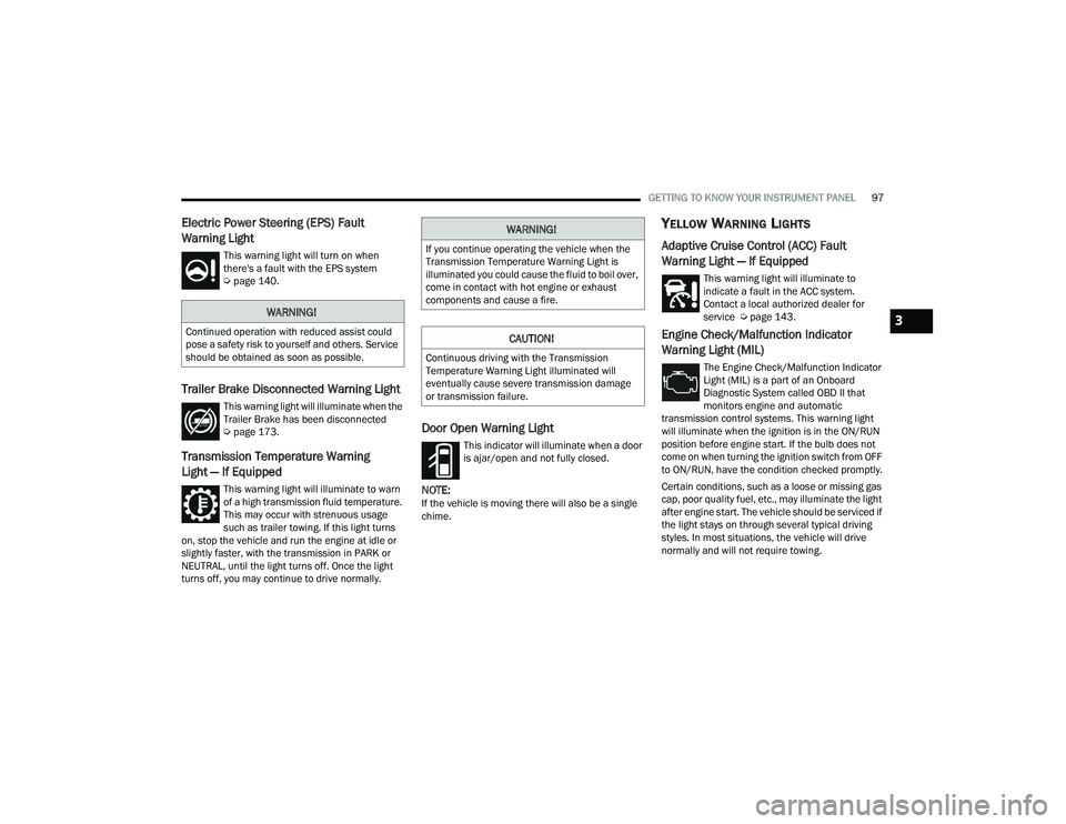
Electric Power Steering (EPS) Fault
Warning Light
This warning light will turn on when
there's a fault with the EPS system
Úpage 140.
Trailer Brake Disconnected Warning Light
This warning light will illuminate when the
Trailer Brake has been disconnected
Úpage 173.
Transmission Temperature Warning
Light — If Equipped
This warning light will illuminate to warn
of a high transmission fluid temperature.
This may occur with strenuous usage
such as trailer towing. If this light turns
on, stop the vehicle and run the engine at idle or
slightly faster, with the transmission in PARK or
NEUTRAL, until the light turns off. Once the light
turns off, you may continue to drive normally.
Door Open Warning Light
This indicator will illuminate when a door
is ajar/open and not fully closed.
NOTE:If the vehicle is moving there will also be a single
chime.
YELLOW WARNING LIGHTS
Adaptive Cruise Control (ACC) Fault
Warning Light — If Equipped
This warning light will illuminate to
indicate a fault in the ACC system.
Contact a local authorized dealer for
service Ú page 143.
Engine Check/Malfunction Indicator
Warning Light (MIL)
The Engine Check/Malfunction Indicator
Light (MIL) is a part of an Onboard
Diagnostic System called OBD II that
monitors engine and automatic
transmission control systems. This warning light
will illuminate when the ignition is in the ON/RUN
position before engine start. If the bulb does not
come on when turning the ignition switch from OFF
to ON/RUN, have the condition checked promptly.
Certain conditions, such as a loose or missing gas
cap, poor quality fuel, etc., may illuminate the light
after engine start. The vehicle should be serviced if
the light stays on through several typical driving
styles. In most situations, the vehicle will drive
normally and will not require towing.
WARNING!
Continued operation with reduced assist could
pose a safety risk to yourself and others. Service
should be obtained as soon as possible.
WARNING!
If you continue operating the vehicle when the
Transmission Temperature Warning Light is
illuminated you could cause the fluid to boil over,
come in contact with hot engine or exhaust
components and cause a fire.
CAUTION!
Continuous driving with the Transmission
Temperature Warning Light illuminated will
eventually cause severe transmission damage
or transmission failure.
3
22_DPF_OM_EN_USC_t.book Page 97
Page 106 of 428

104GETTING TO KNOW YOUR INSTRUMENT PANEL
EMISSIONS INSPECTION AND
MAINTENANCE PROGRAMS
In some localities, it may be a legal requirement to
pass an inspection of your vehicle's emissions
control system. Failure to pass could prevent
vehicle registration.
For states that require an Inspection and
Maintenance (I/M), this check verifies
the Malfunction Indicator Light (MIL) is
functioning and is not on when the
engine is running, and that the OBD II system is
ready for testing.
Normally, the OBD II system will be ready. The
OBD II system may not be ready if your vehicle was
recently serviced, recently had a depleted battery
or a battery replacement. If the OBD II system
should be determined not ready for the I/M test,
your vehicle may fail the test.
Your vehicle has a simple ignition actuated test,
which you can use prior to going to the test station.
To check if your vehicle's OBD II system is ready,
you must do the following:
1. Cycle the ignition switch to the ON position,
but do not crank or start the engine.
NOTE:If you crank or start the engine, you will have to
start this test over.
2. As soon as you cycle the ignition switch to the ON position, you will see the Malfunction
Indicator Light (MIL) symbol come on as part of
a normal bulb check.
3. Approximately 15 seconds later, one of two things will happen:
The MIL will flash for about 10 seconds and
then return to being fully illuminated until
you turn OFF the ignition or start the engine.
This means that your vehicle's OBD II
system is not ready and you should not
proceed to the I/M station.
The MIL will not flash at all and will remain
fully illuminated until you place the ignition
in the off position or start the engine. This
means that your vehicle's OBD II system is
ready and you can proceed to the I/M
station. If your OBD II system is
not ready, you should see
an authorized dealer or repair facility. If your
vehicle was recently serviced or had a battery
failure or replacement, you may need to do nothing
more than drive your vehicle as you normally would
in order for your OBD II system to update. A
recheck with the above test routine may then
indicate that the system is now ready.
Regardless of whether your vehicle's OBD II system
is ready or not, if the MIL is illuminated during
normal vehicle operation you should have your
vehicle serviced before going to the I/M station.
The I/M station can fail your vehicle because the
MIL is on with the engine running.
22_DPF_OM_EN_USC_t.book Page 104
Page 112 of 428

110STARTING AND OPERATING
3. Push the ENGINE START/STOP button a second time to change the ignition to the RUN
position.
4. Push the ENGINE START/STOP button a third time to return the ignition to the OFF position.
Keyless Enter ‘n Go™ Starting Procedure —
Engine Manifold Air Temperature 0°F To
66°F (–18°C to 19°C)
NOTE:The temperature displayed in the instrument
cluster does not necessarily reflect the engine
manifold air temperature Ú page 81. When
engine temperatures fall below 66°F (19°C) the
“Wait To Start” telltale will remain on indicating the
intake air heater system is active.
Follow the steps in the “Normal Starting”
procedure except:
1. Pushing the engine start button with the driver’s foot on the brake will move the
ignition from OFF or ACC to RUN, and will
illuminate the "Wait to Start" telltale. The
engine will not immediately crank, this is
normal operation.
2. The “Wait to Start" telltale will remain on for a period of time that varies depending on the
engine temperature. 3. While the "Wait to Start" telltale is on, the
instrument cluster will additionally display a
gauge or bar whose initial length represents
the full "Wait to Start" time period. Its length
will decrease until it disappears when the
"Wait to Start" time has elapsed.
4. After the engine “Wait to Start” telltale goes off, the engine will automatically crank.
5. After engine start-up, check to see that there is oil pressure.
6. Release the parking brake and drive.
NOTE:
Engine idle speed will automatically increase to
1,000 RPM and engage the Variable Geometry
Turbocharger at low coolant temperatures to
improve engine warm-up.
The engine will not automatically crank after the
engine "Wait to Start" telltale goes off if a door
or the hood is ajar.
If the engine stalls, or if the ignition switch is left
ON for more than two minutes after the “Wait to
Start” telltale goes out, reset the intake air
heater by turning the ignition switch to the OFF
position for at least 5 seconds and then back
ON. Repeat steps 1 through 6 of “Keyless
Enter ‘n Go™ Starting Procedure – Engine Mani -
fold Air Temperature 0°F To 66°F (–18°C to
19°C).”
EXTREME COLD WEATHER
The Cummins® Turbo Diesel engine is equipped
with several features designed to assist cold
weather starting and operation:
The engine block heater is a resistance heater
installed in the water jacket of the engine just
above and behind the oil filter. It requires a
110–115 Volt AC electrical outlet with a
grounded, three-wire extension cord.
CAUTION!
If the Water in Fuel Indicator Light remains on,
DO NOT START the engine before you drain the
water from the fuel filters to avoid engine
damage Ú page 347.
CAUTION!
Do not crank engine for more than 25 seconds
at a time or starter motor damage may result.
Turn the ignition switch to the OFF position and
wait at least two minutes for the starter to cool
before repeating start procedure.
22_DPF_OM_EN_USC_t.book Page 110
Page 113 of 428

STARTING AND OPERATING111
NOTE:The engine block heater cord is a factory installed
option. If your vehicle is not equipped, heater cords
are available from an authorized Mopar® dealer.
A 12 Volt heater built into the fuel filter housings
aid in preventing fuel gelling. It is controlled by a
built-in thermostat.
An intake air heater system both improves
engine starting and reduces the amount of
white smoke generated by a warming engine.
NORMAL STARTING PROCEDURE —
E
NGINE MANIFOLD AIR TEMPERATURE
A
BOVE 66°F (19°C)
Observe the instrument panel cluster lights when
starting the engine.
1. Always apply the parking brake.
2. Shift into PARK for an automatic transmission.
3. Place the ignition switch in the ON/RUN
position and watch the instrument panel
cluster lights. 4. Place the ignition switch in the START position
and crank the engine. Do not press the
accelerator during starting.
5. Check that the Oil Pressure Warning Light has turned off.
6. Release the parking brake.STARTING PROCEDURE — ENGINE
M
ANIFOLD AIR TEMPERATURE 0°F TO
66°F (–18°C
TO 19°C)
NOTE:The temperature displayed in the instrument
cluster does not necessarily reflect the engine
manifold air temperature Ú page 81. When
engine temperatures fall below 66°F (19°C) the
“Wait To Start” telltale will remain on indicating the
intake air heater system is active.
Follow the steps in the “Normal Starting”
procedure except:
1. The “Wait to Start” telltale will remain on for a
period of time that varies depending on the
engine temperature.
2. While the “Wait to Start” telltale is on, the instrument cluster will additionally display a
gauge or bar whose initial length represents
the full “Wait to Start” time period. Its length
will decrease until it disappears when the
“Wait to Start” time has elapsed.
3. After the “Wait to Start” telltale goes off, place the ignition switch in the START position. Do
not press the accelerator during starting.
CAUTION!
If the Water in Fuel Indicator Light remains on,
DO NOT START the engine before you drain the
water from the fuel filters to avoid engine
damage Ú page 347.
CAUTION!
Do not crank engine for more than 25 seconds
at a time or starter motor damage may result.
Turn the ignition switch to the OFF position and
wait at least two minutes for the starter to cool
before repeating start procedure.
CAUTION!
If the Water in Fuel Indicator Light remains on,
DO NOT START the engine before you drain the
water from the fuel filters to avoid engine
damage Úpage 347.
CAUTION!
Do not crank engine for more than 25 seconds
at a time or starter motor damage may result.
Turn the ignition switch to the OFF position and
wait at least two minutes for the starter to cool
before repeating start procedure.
4
22_DPF_OM_EN_USC_t.book Page 111