fuel type RAM CHASSIS CAB 2022 Owners Manual
[x] Cancel search | Manufacturer: RAM, Model Year: 2022, Model line: CHASSIS CAB, Model: RAM CHASSIS CAB 2022Pages: 428, PDF Size: 20.18 MB
Page 7 of 428
5
LANESENSE — IF EQUIPPED ............................. 156 LaneSense Operation ................................... 156Turning LaneSense On Or Off ....................... 157
LaneSense Warning Message ...................... 157Changing LaneSense Status ........................ 158
PARKVIEW REAR BACK UP CAMERA ............... 159
SURROUND VIEW CAMERA SYSTEM —
IF EQUIPPED ......................................................... 161
TRAILER CAMERAS — IF EQUIPPED..................165
Trailer Surround View Camera System —
If Equipped..................................................... 165
AUX Camera — If Equipped .......................... 168
ENGINE RUNAWAY .............................................. 168
REFUELING THE VEHICLE— GASOLINE
ENGINE ................................................................. 169
Loose Fuel Filler Cap Message .................... 169
REFUELING THE VEHICLE — DIESEL ENGINE .. 169
Diesel Exhaust Fluid ...................................... 170
VEHICLE LOADING ............................................... 172
Gross Vehicle Weight Rating (GVWR) .......... 172
Payload .......................................................... 172
Gross Axle Weight Rating (GAWR) ................ 172
Tire Size.......................................................... 172
Rim Size ......................................................... 172
Inflation Pressure .......................................... 172
Curb Weight ................................................... 172Loading .......................................................... 173 TRAILER TOWING ................................................ 173
Common Towing Definitions......................... 173
Trailer Hitch Type and Maximum Trailer
Weight ............................................................ 176
Trailer Towing Weights (Maximum Trailer
Weight Ratings) ............................................. 176Trailer And Tongue Weight ........................... 177Towing Requirements .................................. 177
Towing Tips ................................................... 182
SNOWPLOW — IF EQUIPPED ............................. 183
Before Plowing............................................... 183
Snowplow Prep Package Model
Availability ...................................................... 183
Over The Road Operation With Snowplow
Attached......................................................... 184
Operating Tips ............................................... 184
General Maintenance ................................... 184
RECREATIONAL TOWING (BEHIND
MOTORHOME) .................................................... 185
Towing This Vehicle Behind Another
Vehicle ........................................................... 185
Recreational Towing — Two-Wheel Drive
Models ........................................................... 185
Recreational Towing — Four-Wheel Drive
Models ........................................................... 186
DRIVING TIPS ....................................................... 188
Driving On Slippery Surfaces ....................... 188
Driving Through Water ................................. 189
MULTIMEDIA
UCONNECT SYSTEMS ......................................... 190
CYBERSECURITY ................................................. 190
UCONNECT SETTINGS ......................................... 191 Customer Programmable Features ............. 191
UCONNECT INTRODUCTION................................ 211
System Overview .......................................... 211Safety And General Information................... 213
UCONNECT MODES ............................................. 213
Steering Wheel Audio Controls .................... 213
Radio Mode .................................................. 214Media Mode ................................................. 221
Phone Mode ................................................. 223
CONNECTED VEHICLE SERVICES —
IF EQUIPPED ........................................................ 233
Is My Vehicle Connected? ............................ 233
Introduction To Connected Vehicle
Services ........................................................ 233
Getting Started With Connected Vehicle
Services ........................................................ 235
Using SiriusXM Guardian™ .......................... 236
Manage My SiriusXM Guardian™ Account .. 247
22_DPF_OM_EN_USC_t.book Page 5
Page 9 of 428
7
SERVICING AND MAINTENANCE
SCHEDULED SERVICING — GASOLINE
ENGINE .................................................................. 328Maintenance Plan – Gasoline Engine.......... 329
SCHEDULED SERVICING — DIESEL ENGINE .... 332
Oil Change Indicator System — Diesel
Engine ............................................................ 332
Perform Service Indicator — Diesel
Engine ............................................................ 333
Maintenance Plan — Diesel Engine ............. 334
ENGINE COMPARTMENT .................................... 338
6.4L Gasoline Engine ................................... 3386.7L Diesel Engine ........................................ 339
Checking Oil Level ......................................... 340
Adding Washer Fluid ..................................... 340
Maintenance-Free Battery ........................... 340
Pressure Washing ......................................... 341
VEHICLE MAINTENANCE .................................... 341
Engine Oil ...................................................... 341Engine Oil Filter ............................................. 342
Engine Air Cleaner Filter ............................... 342
Air Conditioner Maintenance ........................ 344
Accessory Drive Belt Inspection ................... 346
Draining Fuel/Water Separator Filter .......... 347
Engine Mounted Fuel Filter Replacement ... 348
Underbody Mounted Fuel Filter
Replacement ................................................. 349
Priming If The Engine Has Run Out Of
Fuel ................................................................ 350 Intervention Regeneration Strategy —
Message Process Flow ................................ 350
Diesel Exhaust Fluid (DEF) ........................... 351Body Lubrication ........................................... 351Windshield Wiper Blades.............................. 351Exhaust System ............................................ 353
Cooling System ............................................. 354Charge Air Cooler — Inter-Cooler ................. 357
Brake System ............................................... 358
Automatic Transmission ............................... 358
Rear Axle And 4x4 Front Driving Axle Fluid
Level .............................................................. 360
Transfer Case ............................................... 361
Noise Control System Required
Maintenance & Warranty ............................. 361
Fuses.............................................................. 364
Bulb Replacement......................................... 371
TIRES..................................................................... 376
Tire Safety Information ................................. 376
Tires — General Information ......................... 383
Tire Types....................................................... 386
Spare Tires — If Equipped ............................. 387
Wheel And Wheel Trim Care ......................... 389
Snow Traction Devices ................................. 390
Tire Rotation Recommendations ................. 391
DEPARTMENT OF TRANSPORTATION
UNIFORM TIRE QUALITY GRADES ................... 392
Treadwear ...................................................... 392
Traction Grades ............................................. 393Temperature Grades ..................................... 393 STORING THE VEHICLE ....................................... 393
BODYWORK .......................................................... 393
Protection From Atmospheric Agents .......... 393
Body And Underbody Maintenance ............. 394
Preserving The Bodywork ............................. 394
INTERIORS ........................................................... 395
Seats And Fabric Parts ................................. 395
Plastic And Coated Parts .............................. 395
Leather Surfaces........................................... 396
Glass Surfaces ............................................. 396
TECHNICAL SPECIFICATIONS
VEHICLE IDENTIFICATION NUMBER (VIN) ....... 397
BRAKE SYSTEM .................................................. 397Hydraulic Brake Assist — If Equipped .......... 397
WHEEL AND TIRE TORQUE SPECIFICATIONS .. 397
Torque Specifications ................................... 397
FUEL REQUIREMENTS— GASOLINE ENGINE .... 399
6.4L Engine ................................................... 399
Reformulated Gasoline................................. 399
Materials Added To Fuel ............................... 399
Gasoline/Oxygenate Blends ......................... 399
Do Not Use E-85 In Non-Flex Fuel
Vehicles ......................................................... 400
CNG And LP Fuel System Modifications ...... 400Methylcyclopentadienyl Manganese
Tricarbonyl (MMT) In Gasoline ..................... 400Fuel System Cautions ................................... 400
22_DPF_OM_EN_USC_t.book Page 7
Page 87 of 428

GETTING TO KNOW YOUR INSTRUMENT PANEL85
Fuel Economy
Push and release the up or down arrow
button until the Fuel Economy menu item is
highlighted in the instrument cluster display. Push
and Hold the right arrow button to reset
Average Fuel Economy.
Current Fuel Economy Gauge
Average Fuel Economy Value
Range To Empty
Fuel Tank Levels — If Equipped
Trip A/Trip B
Push and release the up or down arrow
button until the Trip menu item is highlighted in the
instrument cluster display. Push and release the
right arrow button to enter the submenus of
Trip A and Trip B. The Trip A or Trip B information
will display the following:
Distance
Average Fuel Economy
Elapsed Time
Push and hold right arrow button to reset all
information.
Trailer Tow
Push and release the up or down arrow
button until the Trailer Tow menu item is
highlighted in the instrument cluster display. Push
and release the right or left arrow button to
cycle through the following trailer tow information:
Trip (trailer specific) Distance: Push and hold
the OK button to reset the distance.
Integrated Trailer Brake Module (ITBM):
Braking Output
Trailer Type
ITBM Gain
Trailer Light Check: Push and hold the OK
button to begin the Trailer Light Test sequence
Ú page 181.
Trailer Tire Pressure Monitoring: The Instrument
Cluster Display will display the Trailer Tire Pres -
sure for a connected trailer with sensors that
match the active trailer profile. When a low tire
is present, the low tire value will be displayed in
red, and the affected low tire will have a red
glow. “Trailer Tire Low“ will be displayed on the
center bottom of the Instrument Cluster Display
screen.
Audio
Push and release the up or down arrow
button until the Audio Menu icon/title is
highlighted in the instrument cluster display. This
menu will display the audio source information,
including the Song name, Artist name, and audio
source with an accompanying graphic.
Phone Call Status
When a call is incoming, a Phone Call Status
pop-up will display on the screen. The pop-up will
remain until the phone is answered or ignored.
NOTE:The call status will temporarily replace the
previous media source information displayed on
the screen. When the pop-up is no longer
displayed, the display will return to the last used
screen.
Stored Messages
Push and release the up or down arrow
button until the Messages Menu item is
highlighted. This feature shows the number of
stored warning messages. Push and release the
right or left arrow button to cycle through
stored messages.
3
22_DPF_OM_EN_USC_t.book Page 85
Page 110 of 428

108STARTING AND OPERATING
release the accelerator pedal and the brake pedal,
wait 10 to 15 seconds, then repeat the “Normal
Starting” procedure. If the engine has been flooded, it may start to run,
but not have enough power to continue running
when the ignition button/key is released. If this
occurs, continue cranking with the accelerator
pedal pushed all the way to the floor. Release the
accelerator pedal and the ignition button/key once
the engine is running smoothly.
If the engine shows no sign of starting after a
10 second period of engine cranking with the
accelerator pedal held to the floor, wait 10 to
15 seconds, then repeat the “Normal Starting”
procedure.
COLD WEATHER OPERATION
(BELOW –22°F OR −30°C)
To ensure reliable starting at these temperatures,
use of an externally powered electric engine block
heater (available from an authorized dealer) is
recommended.
AFTER STARTING
The idle speed is controlled automatically, and it
will decrease as the engine warms up.
STARTING THE ENGINE — DIESEL ENGINE
Before starting your vehicle, adjust your seat,
adjust both inside and outside mirrors, and fasten
your seat belts.The starter should not be operated for more than
25-second intervals. Waiting a few minutes
between such intervals will protect the starter from
overheating.
WARNING!
Never pour fuel or other flammable liquid into
the throttle body air inlet opening in an
attempt to start the vehicle. This could result
in flash fire causing serious personal injury.
Do not attempt to push or tow your vehicle to
get it started. Vehicles equipped with an auto
-
matic transmission cannot be started this
way. Unburned fuel could enter the catalytic
converter and once the engine has started,
ignite and damage the converter and vehicle.
If the vehicle has a discharged battery,
booster cables may be used to obtain a start
from a booster battery or the battery in
another vehicle. This type of start can be
dangerous if done improperly Ú page 320.
CAUTION!
To prevent damage to the starter, do not crank
the engine for more than 10 seconds at a time.
Wait 10 to 15 seconds before trying again.
WARNING!
Do not leave children or animals inside parked
vehicles in hot weather. Interior heat build-up
may cause serious injury or death.
When leaving the vehicle, always remove the
key fob and lock your vehicle.
Never leave children alone in a vehicle, or with
access to an unlocked vehicle. Allowing chil -
dren to be in a vehicle unattended is
dangerous for a number of reasons. A child or
others could be seriously or fatally injured.
Children should be warned not to touch the
parking brake, brake pedal or the gear
selector. Do not leave the key fob in or near
the vehicle (or in a location accessible to chil -
dren), and do not leave the ignition of a
vehicle equipped with Keyless Enter ‘n Go™ in
the ACC or ON/RUN position. A child could
operate power windows, other controls, or
move the vehicle.
22_DPF_OM_EN_USC_t.book Page 108
Page 120 of 428
118STARTING AND OPERATING
Do Not Operate The Engine With Failed
Parts
All engine failures give some warning before the
parts fail. Be on the alert for changes in
performance, sounds, and visual evidence that the
engine requires service. Some important clues are:
Engine misfiring or vibrating severely.
Sudden loss of power.
Unusual engine noises.
Fuel, oil or coolant leaks.
Sudden change, outside the normal operating
range, in the engine operating temperature.
Excessive smoke.
Oil pressure drop.
DIESEL PARTICULATE FILTER (DPF)
M
ANUAL REGENERATION — IF EQUIPPED
On equipped Chassis Cabs, a manual regeneration
can be enable through the instrument cluster. The
manual regeneration will allow the DPF to
complete a regeneration, lowering the soot level
without having to drive the vehicle. The vehicle
must be in PARK to access this feature, and the
fuel level must be over 12.5% full. A message
displaying the time left on the regeneration will
appear on the instrument cluster, and the
instrument cluster will display the soot level
Ú page 81.
ENGINE BLOCK HEATER — IF EQUIPPED
The engine block heater warms the engine, and
permits quicker starts in cold weather. Connect the
cord to a standard 110-115 Volt AC electrical
outlet with a grounded, three-wire extension cord.
The engine block heater cord is routed behind the
front bumper and accessible through the right hole
of the air dam.
The engine block heater must be plugged in at
least one hour to have an adequate warming effect
on the engine.
It includes a removable cap that is secured by a
tethered strap. It also has a c-clip that is used for
storage when not in use for the Winter months.
During Winter months, remove the heater cord
wiring assembly from itself on the c-clip.
NOTE:The block heater will require 110 Volt AC and
6.5 Amps to activate the heater element.
Block Heater Usage
For ambient temperatures below 0°F (-18°C),
engine block heater usage is recommended.
For ambient temperatures below –20°F (-29°C),
engine block heater usage is required.
ENGINE BREAK-IN RECOMMENDATIONS —
GASOLINE ENGINE
A long break-in period is not required for the engine
and drivetrain (transmission and axle) in your
vehicle.
Drive moderately during the first 300 miles
(500 km). After the initial 60 miles (100 km),
speeds up to 50 or 55 mph (80 or 90 km/h) are
desirable.
While cruising, brief full-throttle acceleration within
the limits of local traffic laws contributes to a good
break-in. Wide-open throttle acceleration in low
gear can be detrimental and should be avoided.
The engine oil installed in the engine at the factory
is a high-quality energy conserving type lubricant.
Oil changes should be consistent with anticipated
climate conditions under which vehicle operations
will occur. For the recommended viscosity and
quality grades Ú page 404.
NOTE:A new engine may consume some oil during its first
few thousand miles (kilometers) of operation. This
should be considered a normal part of the break-in
CAUTION!
Never use Non-Detergent Oil or Straight Mineral
Oil in the engine or damage may result.
22_DPF_OM_EN_USC_t.book Page 118
Page 133 of 428

STARTING AND OPERATING131
When To Use TOW/HAUL Mode
When driving in hilly areas, towing a trailer, carrying
a heavy load, etc., and frequent transmission
shifting occurs, push the TOW/HAUL switch to
activate TOW/HAUL mode. This will improve
performance and reduce the potential for
transmission overheating or failure due to
excessive shifting. When operating in TOW/HAUL
mode, transmission upshifts are delayed, and the
transmission will automatically downshift (for
engine braking) when the throttle is closed and/or
during steady braking maneuvers.
TOW/HAUL Switch
The TOW/HAUL Indicator Light will illuminate in the
instrument cluster to indicate that TOW/HAUL
mode has been activated. Pushing the switch a
second time restores normal operation. Normal operation is always the default at engine start-up.
If TOW/HAUL mode is desired, the switch must be
pushed each time the engine is started.
Torque Converter Clutch
A feature designed to improve fuel economy has
been included in the automatic transmission on
your vehicle. A clutch within the torque converter
engages automatically at calibrated speeds. This
may result in a slightly different feeling or response
during normal operation in the upper gears. When
the vehicle speed drops or during some
accelerations, the clutch automatically
disengages.
NOTE:
The torque converter clutch will not engage,
until the transmission fluid and engine coolant
are warm (usually after 1 to 3 miles (2 to 5 km)
of driving). Because engine speed is higher
when the torque converter clutch is not engaged, it may seem as if the transmission is
not shifting properly when cold; this is normal.
Using the Electronic Range Select (ERS) shift
control, when the transmission is sufficiently
warm, will demonstrate that the transmission is
able to shift into and out of Overdrive.
If the vehicle has not been driven for several
days, the first few seconds of operation after
shifting the transmission into gear may seem
sluggish. This is due to the fluid partially
draining from the torque converter into the
transmission. This condition is normal and will
not cause damage to the transmission. The
torque converter will refill within five seconds
after starting the engine.
AUXILIARY SWITCHES — IF EQUIPPED
There can be up to six auxiliary switches located in
the lower switch bank of the instrument panel
which can be used to power various electronic
devices and Power Take Off (PTO). If equipped, it
will take the place of the sixth auxiliary switch.
Connections to the switches are found under the
hood in the connectors attached to the auxiliary
Power Distribution Center.
You have the ability to configure the functionality of
the auxiliary switches via the instrument cluster
display. All switches can now be configured for
setting the switch type operation to latching or
WARNING!
Do not use the TOW/HAUL feature when driving
in icy or slippery conditions. The increased
engine braking can cause the rear wheels to
slide, and the vehicle to swing around with the
possible loss of vehicle control, which may
cause an accident possibly resulting in personal
injury or death.
4
22_DPF_OM_EN_USC_t.book Page 131
Page 170 of 428
168STARTING AND OPERATING
(Continued)
AUX CAMERA — IF EQUIPPED
Your vehicle may be equipped with one or two AUX
Cameras, which display a rearview image from the
trailer on the touchscreen.
NOTE:Two Aux Cameras are only available on vehicles
with NAV equipped radios if the vehicle is not
equipped with a Center High Mounted Stop Lamp
(CHMSL) and Surround View Camera system.
Activation
The AUX Camera is activated by first pressing the
Backup Camera or Cargo Camera (if equipped)
button on the touchscreen, followed by the AUX
button located in the upper left corner of the rearview display. On vehicles with Surround View
Camera (if equipped), the AUX Camera can be
activated when the vehicle is in REVERSE by first
pressing the More Cams button in the Surround
view screen, followed by the AUX tab. The AUX
camera can also be activated when the vehicle is
in REVERSE by pressing the AUX button.
If equipped with two AUX Cameras, you can switch
between each camera by pressing the AUX 1 or
AUX 2 buttons on the Trailer Camera display.
Deactivation
The AUX Camera is deactivated by pressing the “X”
in the upper right corner of the touchscreen. This
will return the display back to the previously
displayed screen.
NOTE:
If the AUX button is pressed and no AUX Camera
is connected, the touchscreen will display a blue
screen along with the message “Camera
System Unavailable.” The screen can be exited
out by pressing the “X” in the upper right hand
corner. This will return the display back to the
previously displayed screen.
Zoom View is not available with the AUX Camera
feature.
The display will always default to the Trailer
Camera display AUX 1.
ENGINE RUNAWAY
Diesel engine runaway is a rare condition affecting
diesel engines, where the engine consumes its
own lubrication oil and runs at higher and higher
RPM until it overspeeds to a point where it destroys
itself due to either mechanical failure or engine
seizure through lack of lubrication.
CAUTION!
To avoid vehicle damage, Trailer Surround
View should only be used as a parking aid. The
Trailer Surround View Camera is unable to
view every obstacle or object in your drive
path.
To avoid vehicle damage, the vehicle must be
driven slowly when using Trailer Surround
View to be able to stop in time when an
obstacle is seen. It is recommended that the
driver look frequently over his/her shoulder
when using Trailer Surround View.
AUX 1 Camera Button
AUX 2 Camera Button
WARNING!
In case of engine runaway due to flammable
fumes from fuel spills or turbocharger oil leaks
being sucked into the engine, do the following to
help avoid personal injury and/or vehicle
damage:
Turn the ignition switch to the OFF position.
Using a CO2 or dry chemical type fire extin
-
guisher, direct the spray from the fire extin -
guisher into the grille on the passenger side so
that the spray enters the engine air intake.
22_DPF_OM_EN_USC_t.book Page 168
Page 173 of 428
STARTING AND OPERATING171
(Continued)
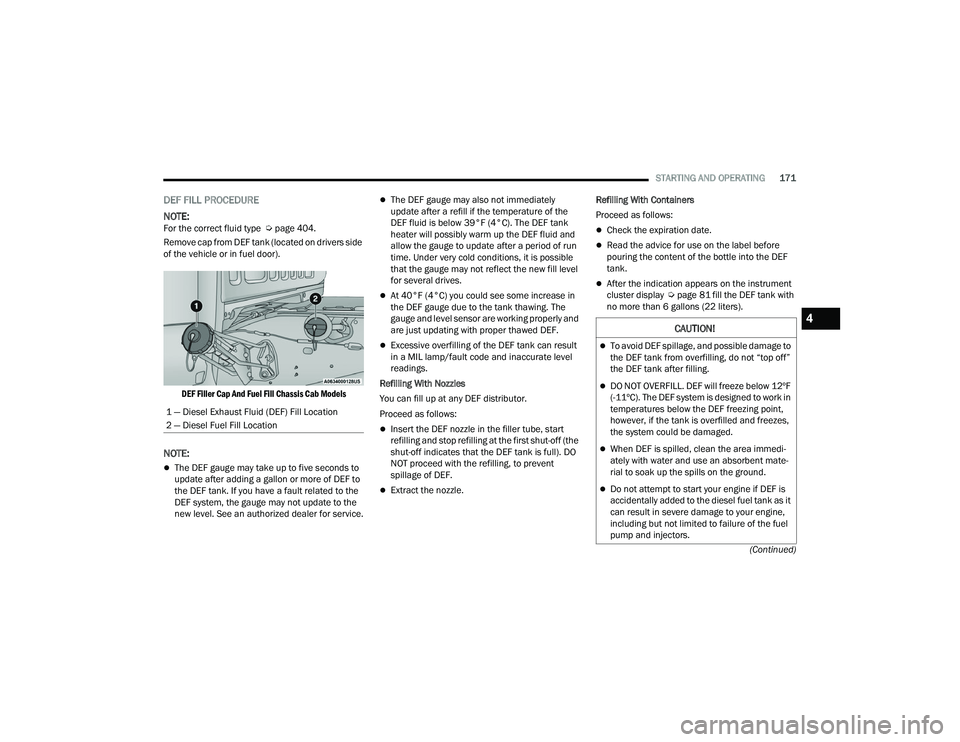
DEF FILL PROCEDURE
NOTE:
For the correct fluid type Ú page 404.
Remove cap from DEF tank (located on drivers side
of the vehicle or in fuel door).
DEF Filler Cap And Fuel Fill Chassis Cab Models
NOTE:
The DEF gauge may take up to five seconds to
update after adding a gallon or more of DEF to
the DEF tank. If you have a fault related to the
DEF system, the gauge may not update to the
new level. See an authorized dealer for service.
The DEF gauge may also not immediately
update after a refill if the temperature of the
DEF fluid is below 39°F (4°C). The DEF tank
heater will possibly warm up the DEF fluid and
allow the gauge to update after a period of run
time. Under very cold conditions, it is possible
that the gauge may not reflect the new fill level
for several drives.
At 40°F (4°C) you could see some increase in
the DEF gauge due to the tank thawing. The
gauge and level sensor are working properly and
are just updating with proper thawed DEF.
Excessive overfilling of the DEF tank can result
in a MIL lamp/fault code and inaccurate level
readings.
Refilling With Nozzles
You can fill up at any DEF distributor.
Proceed as follows:
Insert the DEF nozzle in the filler tube, start
refilling and stop refilling at the first shut-off (the
shut-off indicates that the DEF tank is full). DO
NOT proceed with the refilling, to prevent
spillage of DEF.
Extract the nozzle. Refilling With Containers
Proceed as follows:
Check the expiration date.
Read the advice for use on the label before
pouring the content of the bottle into the DEF
tank.
After the indication appears on the instrument
cluster display
Úpage 81 fill the DEF tank with
no more than 6 gallons (22 liters).
1 — Diesel Exhaust Fluid (DEF) Fill Location
2 — Diesel Fuel Fill Location
CAUTION!
To avoid DEF spillage, and possible damage to
the DEF tank from overfilling, do not “top off”
the DEF tank after filling.
DO NOT OVERFILL. DEF will freeze below 12ºF
(-11ºC). The DEF system is designed to work in
temperatures below the DEF freezing point,
however, if the tank is overfilled and freezes,
the system could be damaged.
When DEF is spilled, clean the area immedi -
ately with water and use an absorbent mate -
rial to soak up the spills on the ground.
Do not attempt to start your engine if DEF is
accidentally added to the diesel fuel tank as it
can result in severe damage to your engine,
including but not limited to failure of the fuel
pump and injectors.
4
22_DPF_OM_EN_USC_t.book Page 171
Page 197 of 428
MULTIMEDIA195
Display
When the Display button is pressed on the touchscreen, the system will display the options related to the theme (if equipped), brightness, and color of the
touchscreen. The available settings are:
NOTE:Depending on the vehicle’s options, feature settings may vary.
Setting Name Description
Language This setting will change the language of the Uconnect system and Instrument
Cluster Display. The available languages are English, Français, and Español.
Display Mode This setting will allow you to set the brightness manually or have the system
set it automatically. The “Auto” setting has the system automatically adjust
the display brightness. The “Manual” setting will allow the user to adjust the
brightness of the display.
Display Brightness With Headlights ON/Brightness This setting will allow you to set the brightness when the headlights are on. To
access this setting, Display Mode must be set to Manual. The “+” setting will
increase the brightness; the “-” will decrease the brightness.
Display Brightness With Headlights OFF/Brightness This setting will allow you to set the brightness when the headlights are off. To
access this setting, Display Mode must be set to Manual. The “+” setting will
increase the brightness; the “-” will decrease the brightness.
Set Theme This setting will allow you to change the display theme.
Units The available settings are “Speed” (MPH or km/h), “Distance” (mi or km),
“Fuel Consumption” (MPG [US], MPG [UK], L/100 km, or km/L), “Pressure”
(psi, kPa, or bar), “Temperature” (°C or °F), Power” (HP [US], Gal HP [UK], or
kW), and “Torque” (lb-ft or Nm) units of measurement independently.
Keyboard This setting will change the keyboard type on the display. The selectable
keyboards are “ABCDEF Keyboard”, “QWERTY Keyboard”, and “AZERTY
Keyboard”.
5
22_DPF_OM_EN_USC_t.book Page 195
Page 271 of 428

SAFETY269
(Continued)
For example, your vehicle may have a
recommended cold (parked for more than three
hours) placard pressure of 30 psi (207 kPa). If the
ambient temperature is 68°F (20°C) and the
measured tire pressure is 27 psi (186 kPa), a
temperature drop to 20°F (-7°C) will decrease the
tire pressure to approximately 23 psi (158 kPa).
This tire pressure is sufficiently low enough to turn
on the TPMS Warning Light. Driving the vehicle
may cause the tire pressure to rise to
approximately 27 psi (186 kPa), but the TPMS
Warning Light will still be on. In this situation, the
TPMS Warning Light will turn off only after the tires
are inflated to the vehicle’s recommended cold
placard pressure value Ú
page 412.
NOTE:
The TPMS is not intended to replace normal tire
care and maintenance or to provide warning of
a tire failure or condition.
If your vehicle is not equipped with the Tire Fill
Alert feature the TPMS should not be used as a
tire pressure gauge while adjusting your tire
pressure.
Driving on a significantly underinflated tire
causes the tire to overheat and can lead to tire
failure. Underinflation also reduces fuel effi -
ciency and tire tread life, and may affect the
vehicle’s handling and stopping ability.
The TPMS is not a substitute for proper tire
maintenance, and it is the driver’s responsibility
to maintain correct tire pressure using an accu -
rate tire pressure gauge, even if underinflation
has not reached the level to trigger illumination
of the TPMS Warning Light.
Seasonal temperature changes will affect tire
pressure, and the TPMS will monitor the actual
tire pressure in the tire.
Example: Tire Pressure Monitoring System Display
The Tire Pressure Monitoring System (TPMS) uses
wireless technology with wheel rim mounted
electronic sensors to monitor tire pressure levels.
Sensors, mounted to each wheel as part of the
valve stem, transmit tire pressure readings to the
receiver module.
CAUTION!
The TPMS has been optimized for the original
equipment tires and wheels. TPMS pressures
and warning have been established for the tire
size equipped on your vehicle. Undesirable
system operation or sensor damage may
result when using replacement equipment
that is not of the same size, type, and/or style.
Aftermarket wheels can cause sensor
damage.
Using aftermarket tire sealants may cause the
Tire Pressure Monitoring System (TPMS)
sensor to become inoperable. After using an
aftermarket tire sealant it is recommended
that you take your vehicle to an authorized
dealership to have your sensor function
checked.
After inspecting or adjusting the tire pressure
always reinstall the valve stem cap. This will
prevent moisture and dirt from entering the
valve stem, which could damage the TPMS
sensor.
CAUTION!
6
22_DPF_OM_EN_USC_t.book Page 269