warning lights RAM CHASSIS CAB 2023 Owner's Manual
[x] Cancel search | Manufacturer: RAM, Model Year: 2023, Model line: CHASSIS CAB, Model: RAM CHASSIS CAB 2023Pages: 444, PDF Size: 20.51 MB
Page 146 of 444

144STARTING AND OPERATING
NOTE:The transfer case N (Neutral) button is located on
the lower left hand corner of the four-wheel drive
Control Switch. The transfer case N (Neutral)
position is to be used for recreational towing only
Úpage 194.
Transfer Case Position Indicator Lights
The Transfer Case Position Indicator Lights (4WD
and 4WD LOW) are located in the instrument
cluster and indicate the current and desired
transfer case selection. When you select a
different transfer case position, the indicator lights
will do the following:
If All Of The Following Shift Conditions Are Met:
1. The current position indicator light will turn off.
2. The selected position indicator light will flash until the transfer case completes the shift.
3. When the shift is complete, the indicator light for the selected position will stop flashing and
remain on.
If One Or More Of The Following Shift Conditions
Are Not Met:
1. The indicator light for the current position will remain on.
2. The newly selected position indicator light will continue to flash. 3. The transfer case
will not shift.NOTE:Before retrying a selection, make certain that all
the necessary requirements for selecting a new
transfer case position have been met. To retry the
selection, turn the control switch back to the
current position, wait five seconds, and retry
selection Ú page 144.
The SERV 4WD Warning Light monitors the
electronically shifted four-wheel drive system. If
this light remains on after engine start-up or
illuminates during driving, it means that the
four-wheel drive system is not functioning properly
and that service is required.
NOTE:Do not attempt to make a shift while only the front
or rear wheels are spinning, as this can cause
damage to driveline components. When operating your vehicle in 4WD LOW, the
engine speed is approximately three times that of
the two-wheel drive or 4WD HIGH positions at a
given road speed. Take care not to overspeed the
engine and do not exceed 25 mph (40 km/h).
Proper operation of four-wheel drive vehicles
depends on tires of equal size, type and
circumference on each wheel. Any difference in
tire size can cause damage to the drivetrain.
Because four-wheel drive provides improved
traction, there is a tendency to exceed safe turning
and stopping speeds. Do not go faster than road
conditions permit.
Shifting Procedure
NOTE:
If any of the requirements to select a new
transfer case position have not been met, the
transfer case will not shift. The position indi
-
cator light for the previous position will remain
ON and the newly selected position indicator
light will continue to flash until all the require -
ments for the selected position have been met.
To retry a shift: return the control switch back to
the original position, make certain all shift
requirements have been met, wait five seconds
and try the shift again.WARNING!
Always engage the parking brake when powering
down the vehicle if the SERV 4WD Warning Light
is illuminated. Not engaging the parking brake
may allow the vehicle to roll, which may cause
personal injury.
23_DPF_OM_EN_USC_t.book Page 144
Page 157 of 444

STARTING AND OPERATING155
Distance Settings
To increase the distance setting, push the
Distance Increase button and release. Each time
the button is pushed, the distance setting
increases by one bar (longer).
To decrease the distance setting, push the
Distance Decrease button and release. Each time
the button is pushed, the distance setting
decreases by one bar (shorter).
If there is no vehicle ahead, the vehicle will
maintain the set speed. If a slower moving vehicle
is detected in the same lane, the instrument
cluster displays the ACC Set With Target Detected Indicator Light, and the system adjusts vehicle
speed automatically to maintain the distance
setting, regardless of the set speed.
NOTE:If the vehicles Integrated Trailer Brake Module
(ITBM) detects a trailer is connected to the vehicle,
and ACC is enabled, the system will increase the
distance to the longest distance setting (four bars)
by default.
The vehicle will then maintain the set distance
until:
The vehicle ahead accelerates to a speed above
the set speed.
The vehicle ahead moves out of your lane or
view of the sensor.
The distance setting is changed.
The system disengages.
The maximum braking applied by ACC is limited;
however, the driver can always apply the brakes
manually, if necessary.
NOTE:The brake lights will illuminate whenever the ACC
system applies the brakes.
A Proximity Warning will alert the driver if ACC
predicts that its maximum braking level is not
sufficient to maintain the set distance. If this
occurs, a visual alert “BRAKE!” will flash in the
instrument cluster display and a chime will sound while ACC continues to apply its maximum braking
capacity.
NOTE:The “BRAKE!” screen in the instrument cluster
display is a warning for the driver to take action
and does not mean that the Forward Collision
Warning system is applying the brakes autono-
mously.
Overtake Aid
When driving with ACC engaged and following a
vehicle, the system will provide an additional
acceleration up to the ACC set speed to assist in
passing the vehicle. This additional acceleration is
triggered when the driver utilizes the left turn
signal and will only be active when passing on the
left hand side.
ACC Operation At Stop
If the ACC system brings your vehicle to a standstill
while following a vehicle ahead, your vehicle will
resume motion, without any driver interaction, if
the vehicle ahead starts moving within two
seconds of your vehicle coming to a standstill.
If the vehicle in front does not start moving within
two seconds of your vehicle coming to a standstill,
the ACC with Stop system will cancel and the
brakes will release. A cancel message will display
on the instrument cluster display and produce a
warning chime. The driver must now manually
operate the vehicle’s accelerator and brakes.
1 — Longest Distance Setting (Four Bars)
2 — Medium Distance Setting (Two Bars)
3 — Long Distance Setting (Three Bars)
4 — Short Distance Setting (One Bar)
4
23_DPF_OM_EN_USC_t.book Page 155
Page 192 of 444
190STARTING AND OPERATING
Display Messages
The trailer brake control interacts with the
instrument cluster display. Display messages,
along with a single chime, will be displayed when a
malfunction is determined in the trailer
connection, trailer brake control, or on the trailer
Ú page 89.
NOTE:
An aftermarket controller may be available for
use with trailers with air or EOH trailer brake
systems. To determine the type of brakes on
your trailer and the availability of controllers,
check with your trailer manufacturer or dealer.
Removal of the ITBM will cause errors and it
may cause damage to the electrical system and
electronic modules of the vehicle. See an autho -
rized dealer if an aftermarket module is to be
installed.
Towing Requirements — Trailer Lights And
Wiring
Whenever you pull a trailer, regardless of the trailer
size, stoplights and turn signals on the trailer are
required for motoring safety.
The Trailer Tow Package may include a four- and
seven-pin wiring harness. Use a factory approved
trailer harness and connector.
NOTE:Do not cut or splice wiring into the vehicle’s wiring
harness.
The electrical connections are all complete to the
vehicle but you must mate the harness to a trailer
connector. Refer to the following illustrations.
NOTE:
Disconnect the trailer wiring connector from the
vehicle (or any other device plugged into
vehicle’s electrical connectors) before
launching a boat into water.
Be sure to reconnect once clear from water
area.
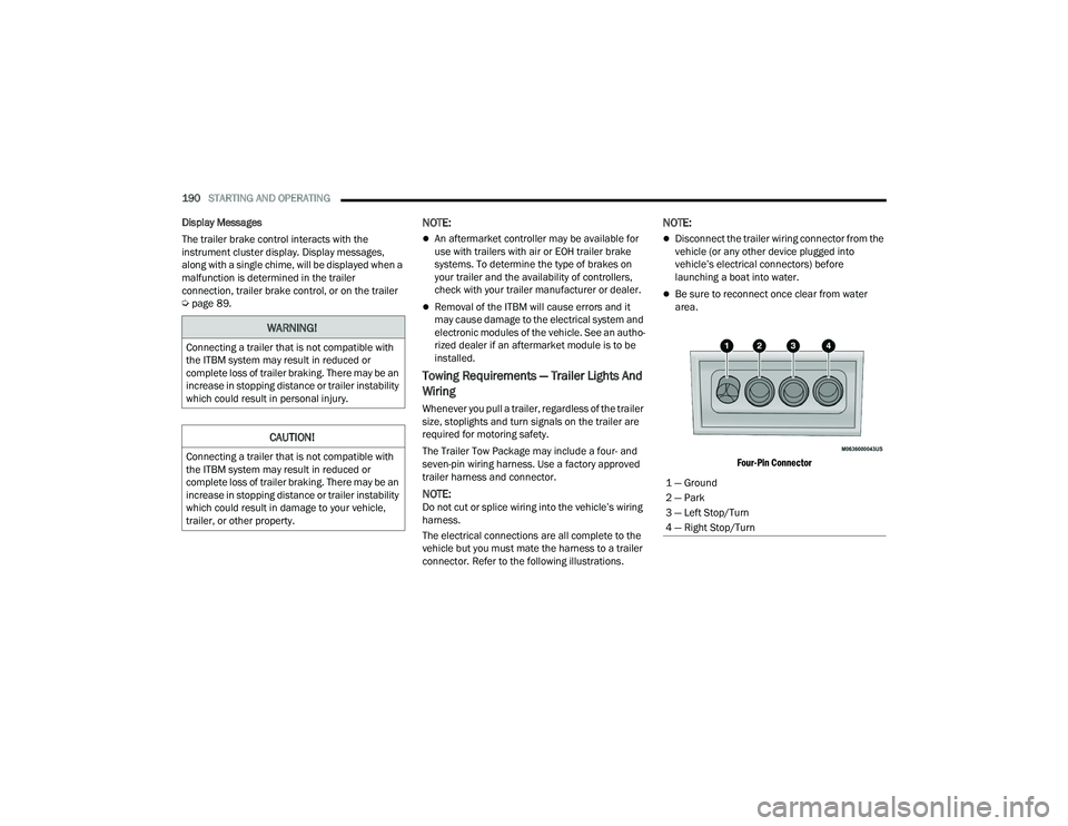
Four-Pin Connector
WARNING!
Connecting a trailer that is not compatible with
the ITBM system may result in reduced or
complete loss of trailer braking. There may be an
increase in stopping distance or trailer instability
which could result in personal injury.
CAUTION!
Connecting a trailer that is not compatible with
the ITBM system may result in reduced or
complete loss of trailer braking. There may be an
increase in stopping distance or trailer instability
which could result in damage to your vehicle,
trailer, or other property.
1 — Ground
2 — Park
3 — Left Stop/Turn
4 — Right Stop/Turn
23_DPF_OM_EN_USC_t.book Page 190
Page 198 of 444
196STARTING AND OPERATING
Shifting Into N (Neutral)
Use the following procedure to prepare your
vehicle for recreational towing.
1. Bring the vehicle to a complete stop on level
ground, with the engine running. Firmly apply
the parking brake.
2. Shift the transmission to NEUTRAL.
3. Press and hold the brake pedal. 4. Shift the transfer case into N (Neutral):With manual shift transfer case, shift the
transfer case lever into N (Neutral).
With electronically shifted transfer case,
push and hold the transfer case N (Neutral)
button. Some models have a small,
recessed "N" button (at the center of the
transfer case switches) that must be
pressed using a ballpoint pen or similar
object. Other models have a rectangular N
(Neutral) switch, below the rotary transfer
case control knob. The N (Neutral) indicator
light will blink while the shift is in progress.
The light will stop blinking (stay on solid)
when the shift to N (Neutral) is complete.
After the shift is completed and the N
(Neutral) light stays on, release the N
(Neutral) button.
5. Release the parking brake.
6. Shift the transmission into REVERSE.
7. Release the brake pedal for five seconds and ensure that there is no vehicle movement.
8. Repeat steps 6 and 7 with automatic transmission in DRIVE.
9. Shift the transmission to NEUTRAL. Firmly apply the parking brake. Turn off the engine.
For vehicles with Keyless Enter ‘n Go™, push
and hold the ENGINE START/STOP button until
the engine shuts off. 10. Shift the transmission into PARK.
11. Place the ignition in the OFF position, and
remove the key fob.
12. Attach the vehicle to the tow vehicle using a suitable tow bar.
13. Release the parking brake.
NOTE:With electronically shifted transfer case:
Steps 2 through 3 are requirements that must
be met before pushing the N (Neutral) button,
and must continue to be met until the shift has
been completed. If any of these requirements
are not met before pushing the N (Neutral)
button or are no longer met during the shift, the
N (Neutral) indicator light will flash continuously
until all requirements are met or until the N
(Neutral) button is released.
The ignition must be in the ON/RUN position for
a shift to take place and for the position indi -
cator lights to be operable. If the ignition is not
in the ON/RUN position, the shift will not take
place and no position indicator lights will be on
or flashing.
A flashing N (Neutral) position indicator light
indicates that shift requirements have not been
met.
WARNING!
You or others could be injured or killed if you
leave the vehicle unattended with the transfer
case in the N (Neutral) position without first fully
engaging the parking brake. The transfer case N
(Neutral) position disengages both the front and
rear driveshafts from the powertrain, and will
allow the vehicle to roll, even if the automatic
transmission is in PARK. The parking brake
should always be applied when the driver is not
in the vehicle.
CAUTION!
It is necessary to follow these steps to be certain
that the transfer case is fully in N (Neutral)
before recreational towing to prevent damage to
internal parts.
23_DPF_OM_EN_USC_t.book Page 196
Page 218 of 444
216MULTIMEDIA
Suspension/Air Suspension
Key Off Power Delay/Engine Off Power Delay This setting will keep certain electrical features running after the engine is
turned off. When any door is opened, the electronics will deactivate. The
available settings are “0 sec”, “45 sec”, “5 min”, and “10 min”.
Headlight Off Delay This setting will allow you to set the amount of time the headlights remain on
after the vehicle has been turned off. The “+” will increase the amount of
time. The “-” will decrease the amount of time.
Setting Name
Description
When the Suspension/Air Suspension button is pressed on the touchscreen, the system will display settings related to the vehicle’s air suspension.
NOTE:Depending on the vehicle’s options, feature settings may vary.
Setting NameDescription
Display Suspension Messages This setting will display suspension messages in the Instrument Cluster
Display. The “All” setting will display all available messages. The “Warnings
Only” setting will only display warning messages.
Tire Jack Mode This setting will disable the Air Suspension system to assist in changing a
spare tire.
Transport Mode This setting will disable the Air Suspension system for flat towing.
Wheel Alignment Mode This setting must be activated before performing a wheel alignment. Contact
an authorized dealer for further information.
23_DPF_OM_EN_USC_t.book Page 216
Page 249 of 444
MULTIMEDIA247
Edit/Edit Profile:
To manage the details of your SiriusXM
Guardian™ account, such as your contact infor -
mation, password and SiriusXM Guardian™ PIN,
click on the Edit/Edit Profile button to access
the details of your account.
Connected Services Status:
This statement will indicate your SiriusXM
Guardian™-equipped vehicle.
Remote Commands:
For vehicles with an active SiriusXM Guardian™
subscription, press one of these icons and enter
your four-digit SiriusXM Guardian™ Security PIN
to remotely start (if equipped), lock/unlock
doors or sound the horn and flash the lights.
Editing Your Notifications
Notifications are an important element of your
SiriusXM Guardian™ account. For example, any
time you use your remote services (such as
Remote Door Unlock), you can elect to receive a
text message, push notification, and/or E-mail to
notify you of the event. To set up the notifications,
please follow these instructions.
1. Log on to your Owner’s Account at
https://
www.mopar.com/en-us.html (US Residents)
and select “Dashboard”, or www.mopar.ca
(Canadian Residents), select “My Vehicle”
and then “Dashboard”.
2. Click the Edit/Edit Profile button.
3. Once there, select “SiriusXM Guardian™” where you can edit Notification Preferences.
4. You can enter a mobile phone and/or email address to notify you, and you can customize
the types of messages.
USING SIRIUSXM GUARDIAN™
SOS Call — If Equipped
Access To Emergency Services At The Push Of A
Button
SiriusXM Guardian™ In-Vehicle Assistance
Features
With SiriusXM Guardian™, your vehicle has
onboard assistance features located on the
rearview mirror or overhead console designed to
enhance your driving experience if you should ever
need assistance or support.
Description
SOS Call offers a convenient way to get in contact
with a SiriusXM Guardian™ Customer Care agent
in the event of an emergency. When the
connection between the vehicle and the live agent
is made, your vehicle will automatically transmit
location information. In the event of a minor
collision, medical or any other emergency, press
the SOS button to be connected to a call center
agent who can send emergency assistance to your
vehicle’s location.
WARNING!
Some SiriusXM Guardian™ connected services,
including SOS Call and Roadside Assistance
Call, will NOT work without a network connection
compatible with your device.
Center Light Status Description
Off No call activated
Green Active call in progress Red System error
5
23_DPF_OM_EN_USC_t.book Page 247
Page 256 of 444
254MULTIMEDIA
Requirements
Vehicle must have an operable LTE (voice/data)
or 4G (data) network connection compatible
with your device.
Vehicle must have an active subscription that
includes the applicable feature.
Vehicle Finder
Description
The Vehicle Finder feature allows you to find the
location of your vehicle.
You can also sound the horn and flash the lights to
make finding your vehicle even easier.
How It Works
Select the Vehicle Finder function within the
Vehicle Branded App and select the Location tab at
the bottom of the App. Then, press the Vehicle icon
to find your vehicle.
Requirements
Vehicle must be properly equipped with the
Uconnect system.
Vehicle must have an operable LTE (voice/data)
or 4G (data) network connection compatible
with your device.
Vehicle must have an active subscription that
includes the applicable feature.
Vehicle ignition must have been turned on
within 14 days.
4G Wi-Fi Hotspot — If Equipped
Description
4G Wi-Fi Hotspot is an in-vehicle service that
connects your device to an LTE (voice/data) or 4G
(data) network that is ready to go wherever you are.
After you've made your purchase, turn on your
device’s Wi-Fi and connect your devices.
Enables all your passengers to be simultane -
ously connected to the web.
Connect several devices at one time.
Any Wi-Fi-enabled device — such as a laptop or
any other portable-enabled media — can
connect over your private in-vehicle network.
A high-speed, secured connection lets anyone
on your private network access the Web — great
for working and relaxing. Create A 4G Wi-Fi Hotspot For Use In Your Vehicle
How It Works
The 4G Wi-Fi Hotspot feature provides
the vehicle passengers with an internet
access hotspot in the vehicle, using the
radio as an access point. The hotspot will
allow Wi-Fi-enabled in-vehicle devices (such as a
laptop or any other portable-enabled media
device) to wirelessly connect to the internet.
Uconnect offers a complimentary 3-month trial
period that includes 1GB of total data. The trial can
be activated any time within the first year of new
vehicle ownership.
Use one of these three ways to purchase a
subscription to the 4G Wi-Fi Hotspot:
1. From your vehicle’s touchscreen, select the 4G Wi-Fi Hotspot App, and press the How To
Purchase button and follow the instructions.
2. Log onto your Owner’s Site and click the link to the AT&T portal to get set up.
3. For existing Connected Car customers: Push
the ASSIST button to be routed to an AT&T
Customer Care agent who will assist you.
WARNING!
The driver should NEVER use the 4G Wi-Fi
Hotspot while driving the vehicle as doing so
may result in an accident involving serious injury
or death.
23_DPF_OM_EN_USC_t.book Page 254
Page 258 of 444
256MULTIMEDIA
In order to provide the Monthly Vehicle Health
Report, the Uconnect system in your vehicle may
collect and transmit vehicle data to SiriusXM
Guardian™ and to FCA, such as your vehicle’s
health and performance, your vehicle’s location,
your utilization of the features in your vehicle, and
other data.
This data collection and transmission begins when
you enroll in SiriusXM Guardian™ and will continue
even if you cancel your SiriusXM Guardian™
subscription unless you call SiriusXM Guardian™
Customer Care and tell them to deactivate your
Uconnect Services.
Please see the Uconnect Privacy Policy for more
information, located at
www.driveuconnect.com/
connectedservices/privacy.html (US Residents)
or www.driveuconnect.ca (Canadian Residents).
For more information on SiriusXM Guardian™
private policy, see
https://siriusxmcvs.com/
privacy-policy.
NOTE:Your vehicle must be enrolled in an active
subscription with SiriusXM Guardian™ Connected
Services. If you have concerns about the operation,
function or performance of your vehicle, please
take it to an authorized dealer. This report does not
replace regularly scheduled maintenance. Check
the instrument cluster warning lights and cautions
in your vehicle for the most accurate vehicle health
information.
Vehicle Health Alert —If Equipped
Description
Your vehicle will send you an email alert if it senses
a problem with one of your vehicle’s key systems.
For further information, go to your Owner’s
website.
NOTE:Vehicle Health Alert emails require you to register
and activate services. During this process you will
be asked to provide an email address to which the
reports will be sent.
In-Vehicle Notifications — If Equipped
Description
Your vehicle will send you notifications to remind
you when services are needed, or to alert you of
other important information, such as recall
notices. When you receive a notification through
your touchscreen, press OK to dismiss the
message, or press Call Care to speak with a
SiriusXM Guardian™ Customer Care agent.
NOTE:Pressing “OK” or the X button on the pop-up screen
will dismiss or close the pop-up, and the In-Vehicle
Messages mailbox will display. In the Mailbox, you
can reopen messages or delete messages.
Amazon Alexa Skill — If Equipped
Enjoy the convenience of using your voice to
command your vehicle with Amazon Alexa!
With Amazon Alexa, you can connect to your
vehicle and remotely access key services and
features.
If your vehicle is equipped with Uconnect
Navigation, you can send a destination directly to
your vehicle using Alexa.
If you need assistance, you can always ask Alexa
for help, or complete a list of commands by saying:
“Alexa, ask
Here are a few of the many questions you can ask
Alexa:
“Alexa, ask
“Alexa, ask
“Alexa, ask
Chrysler Drive, Auburn Hills, Michigan to my
“Alexa, ask
level of my
23_DPF_OM_EN_USC_t.book Page 256
Page 301 of 444

SAFETY299
Front Air Bag Operation
Front Air Bags are designed to provide additional
protection by supplementing the seat belts. Front
air bags are not expected to reduce the risk of
injury in rear, side, or rollover collisions. The front
air bags will not deploy in all frontal collisions,
including some that may produce substantial
vehicle damage — for example, some pole
collisions, truck underrides, and angle offset
collisions.
On the other hand, depending on the type and
location of impact, front air bags may deploy in
crashes with little vehicle front-end damage but
that produce a severe initial deceleration.
Because air bag sensors measure vehicle
deceleration over time, vehicle speed and damage
by themselves are not good indicators of whether
or not an air bag should have deployed.
Seat belts are necessary for your protection in all
collisions, and also are needed to help keep you in
position, away from an inflating air bag.
When the Occupant Restraint Controller (ORC)
detects a collision requiring the front air bags, it
signals the inflator units. A large quantity of
non-toxic gas is generated to inflate the front air
bags. The steering wheel hub trim cover and the upper
passenger side of the instrument panel separate
and fold out of the way as the air bags inflate to
their full size. The front air bags fully inflate in less
time than it takes to blink your eyes. The front air
bags then quickly deflate while helping to restrain
the driver and front passenger.
Knee Impact Bolsters
The Knee Impact Bolsters help protect the knees
of the driver and front passenger, and position the
front occupants for improved interaction with the
front air bags.
Supplemental Side Air Bags
Supplemental Seat-Mounted Side Air Bags
(SABs) — If Equipped
Your vehicle may be equipped with Supplemental
Seat-Mounted Side Air Bags (SABs). If your vehicle
is equipped with Supplemental Seat-Mounted Side
Air Bags (SABs), please refer to the information
below.
Supplemental Seat-Mounted Side Air Bags (SABs)
are located in the outboard side of the front seats.
The SABs are marked with “SRS AIRBAG” or
“AIRBAG” on a label or on the seat trim on the
outboard side of the seats.
Supplemental Seat-Mounted Side Air Bag Label
WARNING!
Do not drill, cut, or tamper with the knee
impact bolsters in any way.
Do not mount any accessories to the knee
impact bolsters such as alarm lights, stereos,
citizen band radios, etc.
6
23_DPF_OM_EN_USC_t.book Page 299
Page 304 of 444

302SAFETY
Air Bag System Components
NOTE:The Occupant Restraint Controller (ORC) monitors
the internal circuits and interconnecting wiring
associated with electrical Air Bag System Compo -
nents listed below:
Occupant Restraint Controller (ORC)
Air Bag Warning Light
Steering Wheel and Column
Instrument Panel
Knee Impact Bolsters
Driver and Front Passenger Air Bags
Seat Belt Buckle Switch
Supplemental Side Air Bags — If Equipped
Front and Side Impact Sensors — If Equipped
Seat Belt Pretensioners — If Equipped
If A Deployment Occurs
The front air bags are designed to deflate
immediately after deployment.
NOTE:Front and/or side air bags will not deploy in all colli -
sions. This does not mean something is wrong with
the air bag system. If you do have a collision which deploys the air
bags, any or all of the following may occur:
The air bag material may sometimes cause
abrasions and/or skin reddening to the occu
-
pants as the air bags deploy and unfold. The
abrasions are similar to friction rope burns or
those you might get sliding along a carpet or
gymnasium floor. They are not caused by
contact with chemicals. They are not permanent
and normally heal quickly. However, if you
haven’t healed significantly within a few days, or
if you have any blistering, see your doctor imme -
diately.
As the air bags deflate, you may see some
smoke-like particles. The particles are a normal
by-product of the process that generates the
non-toxic gas used for air bag inflation. These
airborne particles may irritate the skin, eyes,
nose, or throat. If you have skin or eye irritation,
rinse the area with cool water. For nose or throat
irritation, move to fresh air. If the irritation
continues, see your doctor. If these particles
settle on your clothing, follow the garment
manufacturer’s instructions for cleaning.
Do not drive your vehicle after the air bags have
deployed. If you are involved in another collision,
the air bags will not be in place to protect you.
NOTE:
Air bag covers may not be obvious in the interior
trim, but they will open during air bag deploy -
ment.
After any collision, the vehicle should be taken
to an authorized dealer immediately.
Enhanced Accident Response System
In the event of an impact, if the communication
network remains intact, and the power remains
intact, depending on the nature of the event, the
ORC will determine whether to have the Enhanced
Accident Response System perform the following
functions:
Cut off fuel to the engine (if equipped).
Cut off battery power to the electric motor
(if equipped).
Flash hazard lights as long as the battery has
power.
WARNING!
Deployed air bags and seat belt pretensioners
cannot protect you in another collision. Have the
air bags, seat belt pretensioners, and the seat
belt retractor assemblies replaced by an
authorized dealer immediately. Also, have the
Occupant Restraint Controller System serviced
as well.
23_DPF_OM_EN_USC_t.book Page 302