check engine RAM CHASSIS CAB 2023 Owners Manual
[x] Cancel search | Manufacturer: RAM, Model Year: 2023, Model line: CHASSIS CAB, Model: RAM CHASSIS CAB 2023Pages: 444, PDF Size: 20.51 MB
Page 7 of 444
5
ENGINE BREAK-IN RECOMMENDATIONS —
DIESEL ENGINE .................................................... 128
PARKING BRAKE ................................................ 128
DIESEL EXHAUST BRAKE (ENGINE BRAKING) .. 129
AUTOMATIC TRANSMISSION.............................. 130 Ignition Park Interlock ................................... 131Brake/Transmission Shift Interlock (BTSI)
System .......................................................... 131
8-Speed Automatic Transmission —
If Equipped .................................................... 132
6-Speed Automatic Transmission —
If Equipped .................................................... 135
AUXILIARY SWITCHES — IF EQUIPPED ............. 139
FOUR-WHEEL DRIVE OPERATION —
IF EQUIPPED ........................................................ 140
Electronically Shifted Transfer Case
(8-Speed Transmission) — If Equipped ....... 140Electronically Shifted Transfer Case
(6-Speed Transmission) —
If Equipped..................................................... 143
Manually Shifted Transfer Case —
If Equipped..................................................... 145
LIMITED-SLIP DIFFERENTIAL ............................ 147
POWER TAKE OFF (PTO) OPERATION —
IF EQUIPPED ........................................................ 147
HYDRAULIC POWER STEERING .........................148
Power Steering Fluid Check .......................... 148
CRUISE CONTROL SYSTEMS — IF EQUIPPED .... 148
Cruise Control ............................................... 149
Adaptive Cruise Control (ACC) ...................... 150 PARKSENSE FRONT/REAR PARK ASSIST —
IF EQUIPPED ....................................................... 159
ParkSense Sensors ....................................... 159
ParkSense Warning Display ......................... 159
ParkSense Display ........................................ 159Enabling And Disabling ParkSense .............. 162
Service The ParkSense Park Assist System ...162
Cleaning The ParkSense System ................. 162
ParkSense System Usage Precautions........ 162
LANESENSE — IF EQUIPPED ............................. 163
LaneSense Operation ................................... 163Turning LaneSense On Or Off ....................... 164
LaneSense Warning Message ...................... 164Changing LaneSense Status ........................ 166
Turn Signal Activated Blind Spot Assist —
If Equipped..................................................... 166
PARKVIEW REAR BACK UP CAMERA............... 166
SURROUND VIEW CAMERA SYSTEM —
IF EQUIPPED ........................................................ 168
TRAILER CAMERAS — IF EQUIPPED ................. 173 Trailer Surround View Camera System —
If Equipped..................................................... 173AUX Camera — If Equipped ........................... 176
ENGINE RUNAWAY ............................................. 176
REFUELING THE VEHICLE—
GASOLINE ENGINE ............................................. 177
Loose Fuel Filler Cap Message ................... 177
REFUELING THE VEHICLE — DIESEL ENGINE... 177
Diesel Exhaust Fluid...................................... 178 VEHICLE LOADING .............................................. 180
Gross Vehicle Weight Rating (GVWR) ......... 180
Payload .......................................................... 180Gross Axle Weight Rating (GAWR)................ 180Tire Size ......................................................... 181
Rim Size ......................................................... 181
Inflation Pressure .......................................... 181Curb Weight ................................................... 181
Loading .......................................................... 181
TRAILER TOWING ................................................ 181
Common Towing Definitions......................... 181
Trailer Hitch Type and Maximum Trailer
Weight ............................................................ 185
Trailer Towing Weights (Maximum Traile
r Weight Ratings) .......................................... 186Trailer And Tongue Weight .......................... 186
Towing Requirements .................................. 186Towing Tips ................................................... 192
SNOWPLOW — IF EQUIPPED.............................. 192
Before Plowing .............................................. 192
Snowplow Prep Package Model Availability....193
Over The Road Operation With Snowplow
Attached......................................................... 193
Operating Tips ............................................... 193General Maintenance ................................... 193
23_DPF_OM_EN_USC_t.book Page 5
Page 9 of 444
7
SAFETY TIPS ........................................................ 321 Transporting Passengers .............................. 321Transporting Pets ......................................... 322
Connected Vehicles....................................... 322
Safety Checks You Should Make Inside The
Vehicle ........................................................... 322Periodic Safety Checks You Should Make
Outside The Vehicle ...................................... 323Exhaust Gas ................................................... 324Carbon Monoxide Warnings ......................... 324
IN CASE OF EMERGENCY
HAZARD WARNING FLASHERS ........................ 325
ASSIST AND SOS SYSTEM — IF EQUIPPED ...... 326
JACKING AND TIRE CHANGING.......................... 329 4500/5500 Models ...................................... 329Preparations For Jacking .............................. 329Jacking Instructions 4500 And
5500 Series ................................................... 330To Stow The Flat Or Spare — If Equipped ... 332
Hub Caps/Wheel Covers —If Equipped ........ 332
JUMP STARTING .................................................. 333
Preparations For Jump Start......................... 333Jump Starting Procedure .............................. 334
IF YOUR ENGINE OVERHEATS ........................... 335
GEAR SELECTOR OVERRIDE .............................. 336 6–Speed Transmission — If Equipped ........ 336 MANUAL PARK RELEASE ................................... 337
8–Speed Transmission — If Equipped ......... 337
FREEING A STUCK VEHICLE .............................. 338
TOWING A DISABLED VEHICLE ......................... 339
Two-Wheel Drive Models .............................. 340Four-Wheel Drive Models ............................. 340
Emergency Tow Hooks — If Equipped .......... 341
ENHANCED ACCIDENT RESPONSE SYSTEM
(EARS) .................................................................. 341
EVENT DATA RECORDER (EDR) ........................ 341
SERVICING AND MAINTENANCE
SCHEDULED SERVICING ................................... 342
Maintenance Plan — Gasoline Engine ......... 344Maintenance Plan — Diesel Engine ............ 346
ENGINE COMPARTMENT .................................... 350
6.4L Gasoline Engine ................................... 3506.7L Diesel Engine ........................................ 351Checking Oil Level ......................................... 352
Adding Washer Fluid .................................... 352
Maintenance-Free Battery ............................ 352
Pressure Washing ......................................... 353 VEHICLE MAINTENANCE .................................... 353
Engine Oil ...................................................... 353
Engine Oil Filter ............................................. 354Engine Air Cleaner Filter .............................. 355
Air Conditioner Maintenance ....................... 357
Accessory Drive Belt Inspection ................... 359Draining Fuel/Water Separator Filter .......... 360
Engine Mounted Fuel Filter Replacement ... 361Underbody Mounted Fuel Filter
Replacement ................................................. 362
Priming If The Engine Has Run Out Of Fuel ...363
Intervention Regeneration Strategy —
Message Process Flow ................................ 364Diesel Exhaust Fluid (DEF) ........................... 364
Body Lubrication ........................................... 364
Windshield Wiper Blades.............................. 365
Exhaust System ............................................ 367
Cooling System ............................................. 368Charge Air Cooler — Inter-Cooler ................. 370
Brake System ............................................... 371Automatic Transmission ............................... 372
Rear Axle And 4x4 Front Driving Axle
Fluid Level ..................................................... 374
Transfer Case ............................................... 374Noise Control System Required
Maintenance & Warranty ............................ 374
Fuses.............................................................. 377
Bulb Replacement ........................................ 384
23_DPF_OM_EN_USC_t.book Page 7
Page 14 of 444
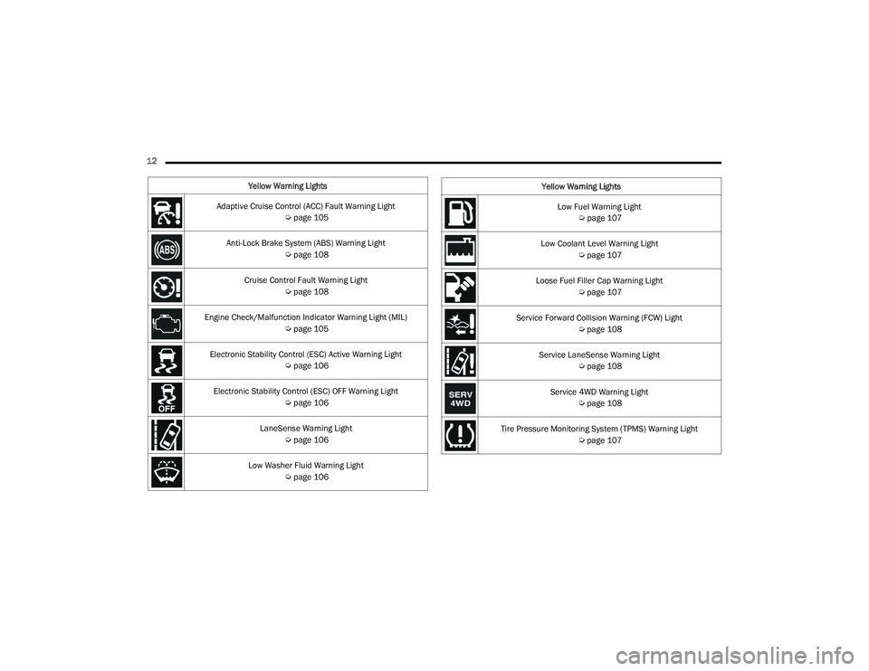
12 Yellow Warning Lights
Adaptive Cruise Control (ACC) Fault Warning Light Úpage 105
Anti-Lock Brake System (ABS) Warning Light Úpage 108
Cruise Control Fault Warning Light Úpage 108
Engine Check/Malfunction Indicator Warning Light (MIL) Úpage 105
Electronic Stability Control (ESC) Active Warning Light Úpage 106
Electronic Stability Control (ESC) OFF Warning Light Úpage 106
LaneSense Warning Light Úpage 106
Low Washer Fluid Warning Light Úpage 106
Low Fuel Warning Light
Úpage 107
Low Coolant Level Warning Light Úpage 107
Loose Fuel Filler Cap Warning Light Úpage 107
Service Forward Collision Warning (FCW) Light Úpage 108
Service LaneSense Warning Light Úpage 108
Service 4WD Warning Light Úpage 108
Tire Pressure Monitoring System (TPMS) Warning Light Úpage 107
Yellow Warning Lights
23_DPF_OM_EN_USC_t.book Page 12
Page 20 of 444
18GETTING TO KNOW YOUR VEHICLE
Duplication of key fobs may be performed at an
authorized dealer. This procedure consists of
programming a blank key fob to the vehicle
electronics. A blank key fob is one that has never
been programmed.
NOTE:
When having the Sentry Key Immobilizer system
serviced, bring all vehicle keys with you to an
authorized dealer.
Keys must be ordered to the correct key cut to
match the vehicle locks.
SENTRY KEY
The Sentry Key Immobilizer system prevents
unauthorized vehicle operation by disabling the
engine. The system does not need to be armed or
activated. Operation is automatic, regardless of
whether the vehicle is locked or unlocked. The system uses a key fob, keyless push button
ignition and a Radio Frequency (RF) receiver to
prevent unauthorized vehicle operation. Therefore,
only key fobs that are programmed to the vehicle
can be used to start and operate the vehicle. The
system cannot reprogram a key fob obtained from
another vehicle.
After placing the ignition in the ON/RUN position,
the Vehicle Security Light will turn on for three
seconds for a bulb check. If the light remains on
after the bulb check, it indicates that there is a
problem with the electronics. In addition, if the light
begins to flash after the bulb check, it indicates
that someone attempted to start the engine with
an invalid key fob. In the event that a valid key fob
is used to start the engine but there is an issue
with the vehicle electronics, the engine will start
and shut off after two seconds.
If the Vehicle Security Light turns on during normal
vehicle operation (vehicle running for longer than
10 seconds), it indicates that there is a fault in the
electronics. Should this occur, have the vehicle
serviced as soon as possible by an authorized
dealer.
All of the key fobs provided with your new vehicle
have been programmed to the vehicle electronics
Ú
page 427.
NOTE:A key fob that has not been programmed is also
considered an invalid key.
IGNITION SWITCH
KEYLESS ENTER ‘N GO™ IGNITION
This feature allows the driver to operate the
ignition switch with the push of a button as long as
the Remote Keyless Entry key fob is in the
passenger compartment.
The Keyless Push Button Ignition has four
operating positions; three of which are labeled and
will illuminate when in position. The three positions
are OFF, ACC, and ON/RUN. The fourth position is
START. During START, RUN will illuminate.
NOTE:In case the ignition switch does not change with
the push of a button, the key fob may have a low or
depleted battery. In this situation, a backup
method can be used to operate the ignition switch.
Put the nose side (side opposite of the emergency
key) of the key fob against the START/STOP
ignition button, with your foot applied on the brake
pedal, and push to operate the ignition switch.
WARNING!
Always remove the key fobs from the vehicle
and lock all doors when leaving the vehicle
unattended.
For vehicles equipped with Keyless
Enter ‘n Go™ Ignition, always remember to
place the ignition in the OFF position when
exiting the vehicle.
CAUTION!
The Sentry Key Immobilizer system is not compatible
with some aftermarket Remote Start systems. Use of
these systems may result in vehicle starting
problems and loss of security protection.
23_DPF_OM_EN_USC_t.book Page 18
Page 81 of 444
GETTING TO KNOW YOUR INSTRUMENT PANEL79
Use this QR code to access your
digital experience.
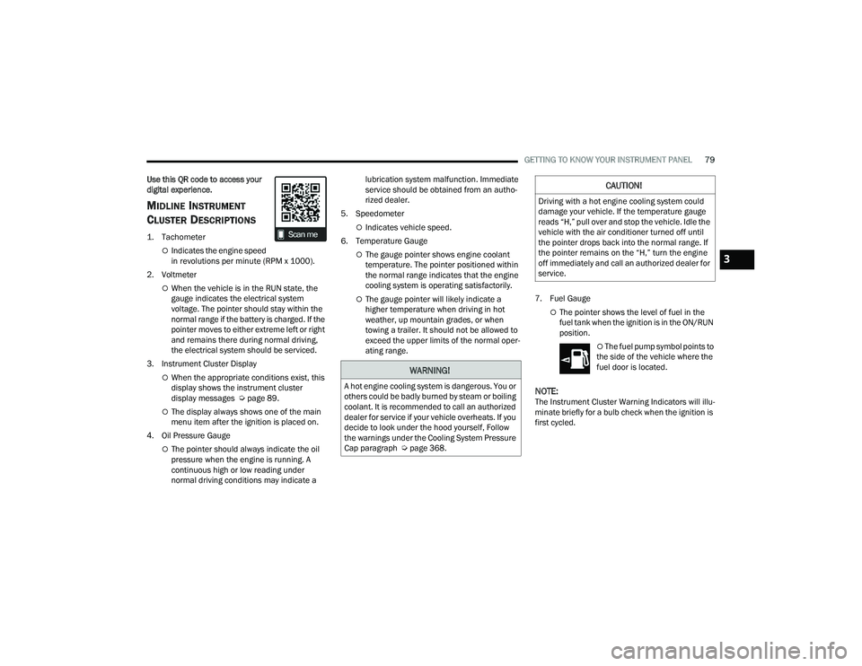
MIDLINE INSTRUMENT
C
LUSTER DESCRIPTIONS
1. Tachometer
Indicates the engine speed
in revolutions per minute (RPM x 1000).
2. Voltmeter
When the vehicle is in the RUN state, the
gauge indicates the electrical system
voltage. The pointer should stay within the
normal range if the battery is charged. If the
pointer moves to either extreme left or right
and remains there during normal driving,
the electrical system should be serviced.
3. Instrument Cluster Display
When the appropriate conditions exist, this
display shows the instrument cluster
display messages Ú page 89.
The display always shows one of the main
menu item after the ignition is placed on.
4. Oil Pressure Gauge
The pointer should always indicate the oil
pressure when the engine is running. A
continuous high or low reading under
normal driving conditions may indicate a lubrication system malfunction. Immediate
service should be obtained from an autho
-
rized dealer.
5. Speedometer
Indicates vehicle speed.
6. Temperature Gauge
The gauge pointer shows engine coolant
temperature. The pointer positioned within
the normal range indicates that the engine
cooling system is operating satisfactorily.
The gauge pointer will likely indicate a
higher temperature when driving in hot
weather, up mountain grades, or when
towing a trailer. It should not be allowed to
exceed the upper limits of the normal oper -
ating range. 7. Fuel Gauge
The pointer shows the level of fuel in the
fuel tank when the ignition is in the ON/RUN
position.
The fuel pump symbol points to
the side of the vehicle where the
fuel door is located.
NOTE:The Instrument Cluster Warning Indicators will illu -
minate briefly for a bulb check when the ignition is
first cycled.
WARNING!
A hot engine cooling system is dangerous. You or
others could be badly burned by steam or boiling
coolant. It is recommended to call an authorized
dealer for service if your vehicle overheats. If you
decide to look under the hood yourself, Follow
the warnings under the Cooling System Pressure
Cap paragraph Ú page 368.
CAUTION!
Driving with a hot engine cooling system could
damage your vehicle. If the temperature gauge
reads “H,” pull over and stop the vehicle. Idle the
vehicle with the air conditioner turned off until
the pointer drops back into the normal range. If
the pointer remains on the “H,” turn the engine
off immediately and call an authorized dealer for
service.
3
23_DPF_OM_EN_USC_t.book Page 79
Page 83 of 444
GETTING TO KNOW YOUR INSTRUMENT PANEL81
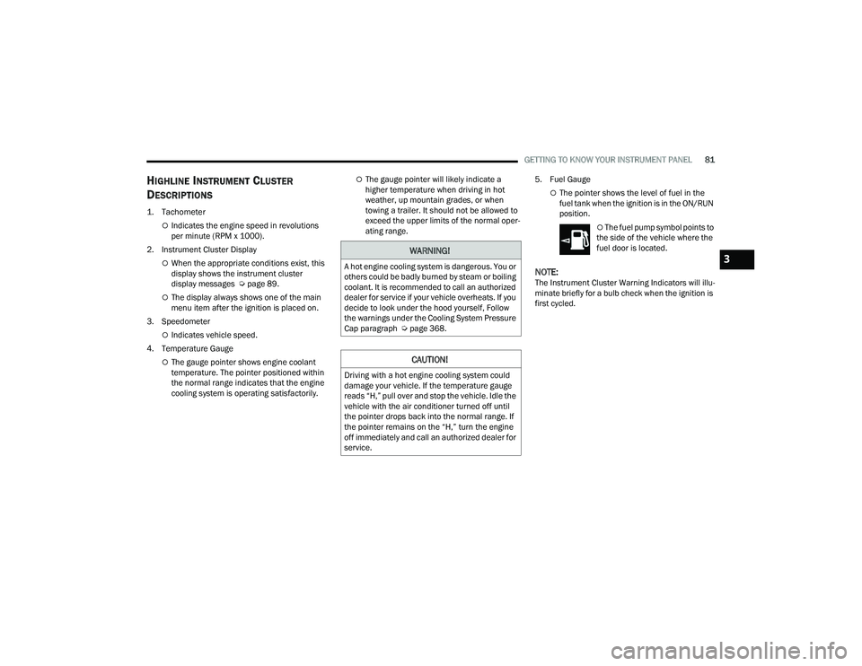
HIGHLINE INSTRUMENT CLUSTER
D
ESCRIPTIONS
1. Tachometer
Indicates the engine speed in revolutions
per minute (RPM x 1000).
2. Instrument Cluster Display
When the appropriate conditions exist, this
display shows the instrument cluster
display messages Ú page 89.
The display always shows one of the main
menu item after the ignition is placed on.
3. Speedometer
Indicates vehicle speed.
4. Temperature Gauge
The gauge pointer shows engine coolant
temperature. The pointer positioned within
the normal range indicates that the engine
cooling system is operating satisfactorily.
The gauge pointer will likely indicate a
higher temperature when driving in hot
weather, up mountain grades, or when
towing a trailer. It should not be allowed to
exceed the upper limits of the normal oper -
ating range. 5. Fuel Gauge
The pointer shows the level of fuel in the
fuel tank when the ignition is in the ON/RUN
position.
The fuel pump symbol points to
the side of the vehicle where the
fuel door is located.
NOTE:The Instrument Cluster Warning Indicators will illu -
minate briefly for a bulb check when the ignition is
first cycled.
WARNING!
A hot engine cooling system is dangerous. You or
others could be badly burned by steam or boiling
coolant. It is recommended to call an authorized
dealer for service if your vehicle overheats. If you
decide to look under the hood yourself, Follow
the warnings under the Cooling System Pressure
Cap paragraph Ú page 368.
CAUTION!
Driving with a hot engine cooling system could
damage your vehicle. If the temperature gauge
reads “H,” pull over and stop the vehicle. Idle the
vehicle with the air conditioner turned off until
the pointer drops back into the normal range. If
the pointer remains on the “H,” turn the engine
off immediately and call an authorized dealer for
service.
3
23_DPF_OM_EN_USC_t.book Page 81
Page 85 of 444
GETTING TO KNOW YOUR INSTRUMENT PANEL83
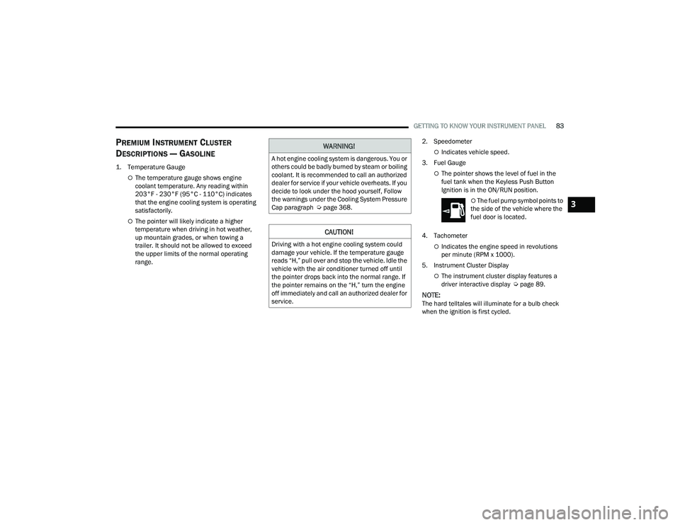
PREMIUM INSTRUMENT CLUSTER
D
ESCRIPTIONS — GASOLINE
1. Temperature Gauge
The temperature gauge shows engine
coolant temperature. Any reading within
203°F - 230°F (95°C - 110°C) indicates
that the engine cooling system is operating
satisfactorily.
The pointer will likely indicate a higher
temperature when driving in hot weather,
up mountain grades, or when towing a
trailer. It should not be allowed to exceed
the upper limits of the normal operating
range. 2. Speedometer
Indicates vehicle speed.
3. Fuel Gauge
The pointer shows the level of fuel in the
fuel tank when the Keyless Push Button
Ignition is in the ON/RUN position.
The fuel pump symbol points to
the side of the vehicle where the
fuel door is located.
4. Tachometer
Indicates the engine speed in revolutions
per minute (RPM x 1000).
5. Instrument Cluster Display
The instrument cluster display features a
driver interactive display Ú page 89.
NOTE:The hard telltales will illuminate for a bulb check
when the ignition is first cycled.
WARNING!
A hot engine cooling system is dangerous. You or
others could be badly burned by steam or boiling
coolant. It is recommended to call an authorized
dealer for service if your vehicle overheats. If you
decide to look under the hood yourself, Follow
the warnings under the Cooling System Pressure
Cap paragraph Úpage 368.
CAUTION!
Driving with a hot engine cooling system could
damage your vehicle. If the temperature gauge
reads “H,” pull over and stop the vehicle. Idle the
vehicle with the air conditioner turned off until
the pointer drops back into the normal range. If
the pointer remains on the “H,” turn the engine
off immediately and call an authorized dealer for
service.
3
23_DPF_OM_EN_USC_t.book Page 83
Page 87 of 444
GETTING TO KNOW YOUR INSTRUMENT PANEL85
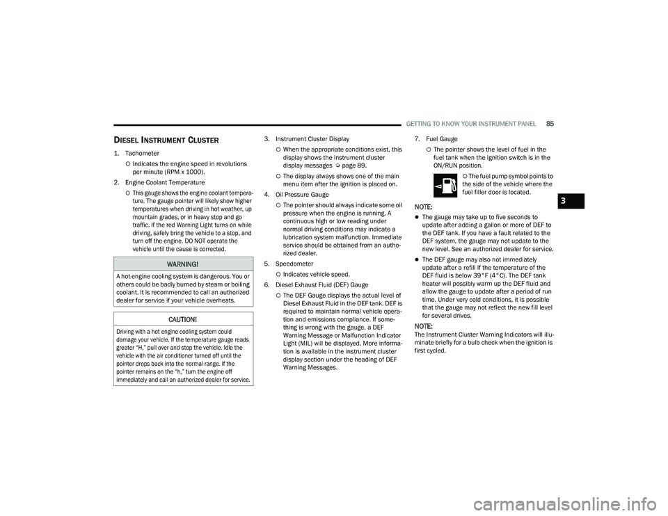
DIESEL INSTRUMENT CLUSTER
1. Tachometer
Indicates the engine speed in revolutions
per minute (RPM x 1000).
2. Engine Coolant Temperature
This gauge shows the engine coolant tempera -
ture. The gauge pointer will likely show higher
temperatures when driving in hot weather, up
mountain grades, or in heavy stop and go
traffic. If the red Warning Light turns on while
driving, safely bring the vehicle to a stop, and
turn off the engine. DO NOT operate the
vehicle until the cause is corrected.
3. Instrument Cluster Display
When the appropriate conditions exist, this
display shows the instrument cluster
display messages Ú
page 89.
The display always shows one of the main
menu item after the ignition is placed on.
4. Oil Pressure Gauge
The pointer should always indicate some oil
pressure when the engine is running. A
continuous high or low reading under
normal driving conditions may indicate a
lubrication system malfunction. Immediate
service should be obtained from an autho -
rized dealer.
5. Speedometer
Indicates vehicle speed.
6. Diesel Exhaust Fluid (DEF) Gauge
The DEF Gauge displays the actual level of
Diesel Exhaust Fluid in the DEF tank. DEF is
required to maintain normal vehicle opera -
tion and emissions compliance. If some -
thing is wrong with the gauge, a DEF
Warning Message or Malfunction Indicator
Light (MIL) will be displayed. More informa -
tion is available in the instrument cluster
display section under the heading of DEF
Warning Messages. 7. Fuel Gauge
The pointer shows the level of fuel in the
fuel tank when the ignition switch is in the
ON/RUN position.
The fuel pump symbol points to
the side of the vehicle where the
fuel filler door is located.
NOTE:
The gauge may take up to five seconds to
update after adding a gallon or more of DEF to
the DEF tank. If you have a fault related to the
DEF system, the gauge may not update to the
new level. See an authorized dealer for service.
The DEF gauge may also not immediately
update after a refill if the temperature of the
DEF fluid is below 39°F (4°C). The DEF tank
heater will possibly warm up the DEF fluid and
allow the gauge to update after a period of run
time. Under very cold conditions, it is possible
that the gauge may not reflect the new fill level
for several drives.
NOTE:The Instrument Cluster Warning Indicators will illu -
minate briefly for a bulb check when the ignition is
first cycled.
WARNING!
A hot engine cooling system is dangerous. You or
others could be badly burned by steam or boiling
coolant. It is recommended to call an authorized
dealer for service if your vehicle overheats.
CAUTION!
Driving with a hot engine cooling system could
damage your vehicle. If the temperature gauge reads
greater “H,” pull over and stop the vehicle. Idle the
vehicle with the air conditioner turned off until the
pointer drops back into the normal range. If the
pointer remains on the “h,” turn the engine off
immediately and call an authorized dealer for service.
3
23_DPF_OM_EN_USC_t.book Page 85
Page 89 of 444
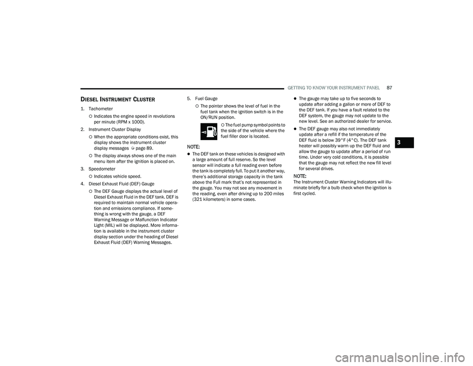
GETTING TO KNOW YOUR INSTRUMENT PANEL87
DIESEL INSTRUMENT CLUSTER
1. Tachometer
Indicates the engine speed in revolutions
per minute (RPM x 1000).
2. Instrument Cluster Display
When the appropriate conditions exist, this
display shows the instrument cluster
display messages Ú page 89.
The display always shows one of the main
menu item after the ignition is placed on.
3. Speedometer
Indicates vehicle speed.
4. Diesel Exhaust Fluid (DEF) Gauge
The DEF Gauge displays the actual level of
Diesel Exhaust Fluid in the DEF tank. DEF is
required to maintain normal vehicle opera -
tion and emissions compliance. If some -
thing is wrong with the gauge, a DEF
Warning Message or Malfunction Indicator
Light (MIL) will be displayed. More informa -
tion is available in the instrument cluster
display section under the heading of Diesel
Exhaust Fluid (DEF) Warning Messages. 5. Fuel Gauge
The pointer shows the level of fuel in the
fuel tank when the ignition switch is in the
ON/RUN position.
The fuel pump symbol points to
the side of the vehicle where the
fuel filler door is located.
NOTE:
The DEF tank on these vehicles is designed with
a large amount of full reserve. So the level
sensor will indicate a full reading even before
the tank is completely full. To put it another way,
there’s additional storage capacity in the tank
above the Full mark that’s not represented in
the gauge. You may not see any movement in
the reading, even after driving up to 200 miles
(321 kilometers) in some cases.
The gauge may take up to five seconds to
update after adding a gallon or more of DEF to
the DEF tank. If you have a fault related to the
DEF system, the gauge may not update to the
new level. See an authorized dealer for service.
The DEF gauge may also not immediately
update after a refill if the temperature of the
DEF fluid is below 39°F (4°C). The DEF tank
heater will possibly warm up the DEF fluid and
allow the gauge to update after a period of run
time. Under very cold conditions, it is possible
that the gauge may not reflect the new fill level
for several drives.
NOTE:The Instrument Cluster Warning Indicators will illu -
minate briefly for a bulb check when the ignition is
first cycled.
3
23_DPF_OM_EN_USC_t.book Page 87
Page 91 of 444
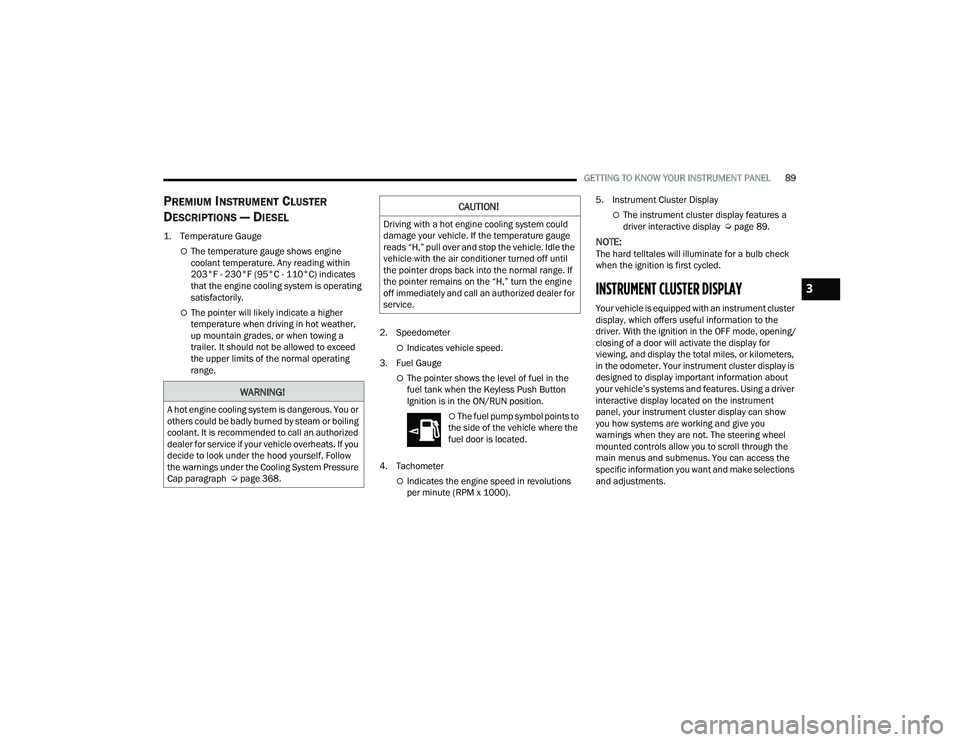
GETTING TO KNOW YOUR INSTRUMENT PANEL89
PREMIUM INSTRUMENT CLUSTER
D
ESCRIPTIONS — DIESEL
1. Temperature Gauge
The temperature gauge shows engine
coolant temperature. Any reading within
203°F - 230°F (95°C - 110°C) indicates
that the engine cooling system is operating
satisfactorily.
The pointer will likely indicate a higher
temperature when driving in hot weather,
up mountain grades, or when towing a
trailer. It should not be allowed to exceed
the upper limits of the normal operating
range. 2. Speedometer
Indicates vehicle speed.
3. Fuel Gauge
The pointer shows the level of fuel in the
fuel tank when the Keyless Push Button
Ignition is in the ON/RUN position.
The fuel pump symbol points to
the side of the vehicle where the
fuel door is located.
4. Tachometer
Indicates the engine speed in revolutions
per minute (RPM x 1000). 5. Instrument Cluster Display
The instrument cluster display features a
driver interactive display Ú
page 89.
NOTE:The hard telltales will illuminate for a bulb check
when the ignition is first cycled.
INSTRUMENT CLUSTER DISPLAY
Your vehicle is equipped with an instrument cluster
display, which offers useful information to the
driver. With the ignition in the OFF mode, opening/
closing of a door will activate the display for
viewing, and display the total miles, or kilometers,
in the odometer. Your instrument cluster display is
designed to display important information about
your vehicle’s systems and features. Using a driver
interactive display located on the instrument
panel, your instrument cluster display can show
you how systems are working and give you
warnings when they are not. The steering wheel
mounted controls allow you to scroll through the
main menus and submenus. You can access the
specific information you want and make selections
and adjustments.
WARNING!
A hot engine cooling system is dangerous. You or
others could be badly burned by steam or boiling
coolant. It is recommended to call an authorized
dealer for service if your vehicle overheats. If you
decide to look under the hood yourself, Follow
the warnings under the Cooling System Pressure
Cap paragraph Úpage 368.
CAUTION!
Driving with a hot engine cooling system could
damage your vehicle. If the temperature gauge
reads “H,” pull over and stop the vehicle. Idle the
vehicle with the air conditioner turned off until
the pointer drops back into the normal range. If
the pointer remains on the “H,” turn the engine
off immediately and call an authorized dealer for
service.
3
23_DPF_OM_EN_USC_t.book Page 89