fuel filter RAM CHASSIS CAB 2023 Owners Manual
[x] Cancel search | Manufacturer: RAM, Model Year: 2023, Model line: CHASSIS CAB, Model: RAM CHASSIS CAB 2023Pages: 444, PDF Size: 20.51 MB
Page 9 of 444
7
SAFETY TIPS ........................................................ 321 Transporting Passengers .............................. 321Transporting Pets ......................................... 322
Connected Vehicles....................................... 322
Safety Checks You Should Make Inside The
Vehicle ........................................................... 322Periodic Safety Checks You Should Make
Outside The Vehicle ...................................... 323Exhaust Gas ................................................... 324Carbon Monoxide Warnings ......................... 324
IN CASE OF EMERGENCY
HAZARD WARNING FLASHERS ........................ 325
ASSIST AND SOS SYSTEM — IF EQUIPPED ...... 326
JACKING AND TIRE CHANGING.......................... 329 4500/5500 Models ...................................... 329Preparations For Jacking .............................. 329Jacking Instructions 4500 And
5500 Series ................................................... 330To Stow The Flat Or Spare — If Equipped ... 332
Hub Caps/Wheel Covers —If Equipped ........ 332
JUMP STARTING .................................................. 333
Preparations For Jump Start......................... 333Jump Starting Procedure .............................. 334
IF YOUR ENGINE OVERHEATS ........................... 335
GEAR SELECTOR OVERRIDE .............................. 336 6–Speed Transmission — If Equipped ........ 336 MANUAL PARK RELEASE ................................... 337
8–Speed Transmission — If Equipped ......... 337
FREEING A STUCK VEHICLE .............................. 338
TOWING A DISABLED VEHICLE ......................... 339
Two-Wheel Drive Models .............................. 340Four-Wheel Drive Models ............................. 340
Emergency Tow Hooks — If Equipped .......... 341
ENHANCED ACCIDENT RESPONSE SYSTEM
(EARS) .................................................................. 341
EVENT DATA RECORDER (EDR) ........................ 341
SERVICING AND MAINTENANCE
SCHEDULED SERVICING ................................... 342
Maintenance Plan — Gasoline Engine ......... 344Maintenance Plan — Diesel Engine ............ 346
ENGINE COMPARTMENT .................................... 350
6.4L Gasoline Engine ................................... 3506.7L Diesel Engine ........................................ 351Checking Oil Level ......................................... 352
Adding Washer Fluid .................................... 352
Maintenance-Free Battery ............................ 352
Pressure Washing ......................................... 353 VEHICLE MAINTENANCE .................................... 353
Engine Oil ...................................................... 353
Engine Oil Filter ............................................. 354Engine Air Cleaner Filter .............................. 355
Air Conditioner Maintenance ....................... 357
Accessory Drive Belt Inspection ................... 359Draining Fuel/Water Separator Filter .......... 360
Engine Mounted Fuel Filter Replacement ... 361Underbody Mounted Fuel Filter
Replacement ................................................. 362
Priming If The Engine Has Run Out Of Fuel ...363
Intervention Regeneration Strategy —
Message Process Flow ................................ 364Diesel Exhaust Fluid (DEF) ........................... 364
Body Lubrication ........................................... 364
Windshield Wiper Blades.............................. 365
Exhaust System ............................................ 367
Cooling System ............................................. 368Charge Air Cooler — Inter-Cooler ................. 370
Brake System ............................................... 371Automatic Transmission ............................... 372
Rear Axle And 4x4 Front Driving Axle
Fluid Level ..................................................... 374
Transfer Case ............................................... 374Noise Control System Required
Maintenance & Warranty ............................ 374
Fuses.............................................................. 377
Bulb Replacement ........................................ 384
23_DPF_OM_EN_USC_t.book Page 7
Page 96 of 444
94GETTING TO KNOW YOUR INSTRUMENT PANEL
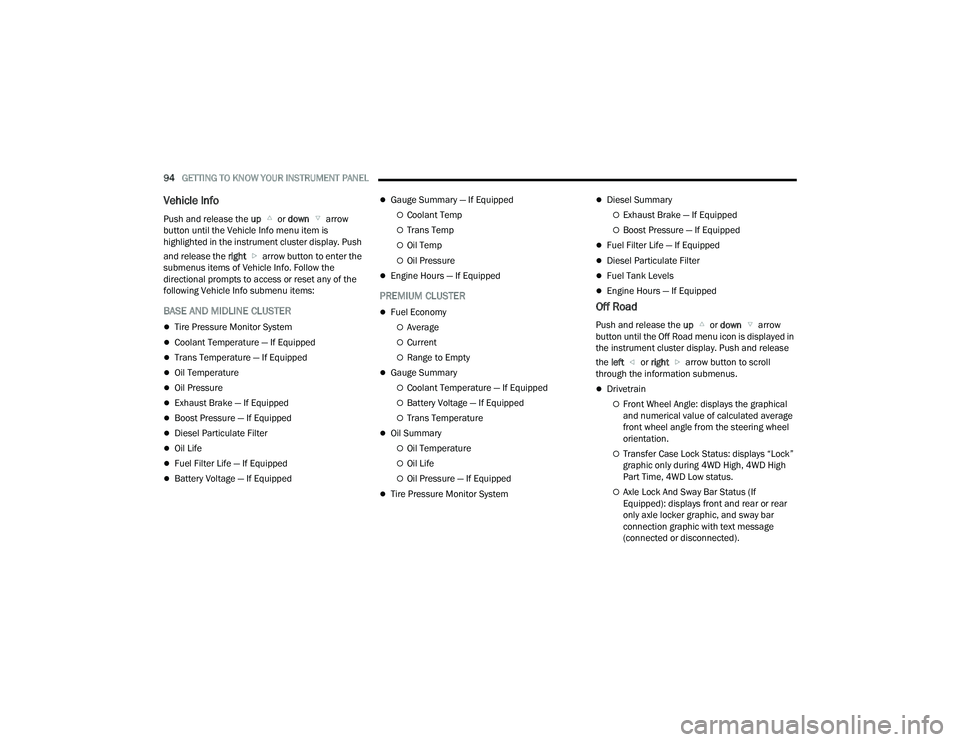
Vehicle Info
Push and release the up or down arrow
button until the Vehicle Info menu item is
highlighted in the instrument cluster display. Push
and release the right arrow button to enter the
submenus items of Vehicle Info. Follow the
directional prompts to access or reset any of the
following Vehicle Info submenu items:
BASE AND MIDLINE CLUSTER
Tire Pressure Monitor System
Coolant Temperature — If Equipped
Trans Temperature — If Equipped
Oil Temperature
Oil Pressure
Exhaust Brake — If Equipped
Boost Pressure — If Equipped
Diesel Particulate Filter
Oil Life
Fuel Filter Life — If Equipped
Battery Voltage — If Equipped
Gauge Summary — If Equipped
Coolant Temp
Trans Temp
Oil Temp
Oil Pressure
Engine Hours — If Equipped
PREMIUM CLUSTER
Fuel Economy
Average
Current
Range to Empty
Gauge Summary
Coolant Temperature — If Equipped
Battery Voltage — If Equipped
Trans Temperature
Oil Summary
Oil Temperature
Oil Life
Oil Pressure — If Equipped
Tire Pressure Monitor System
Diesel Summary
Exhaust Brake — If Equipped
Boost Pressure — If Equipped
Fuel Filter Life — If Equipped
Diesel Particulate Filter
Fuel Tank Levels
Engine Hours — If Equipped
Off Road
Push and release the up or down arrow
button until the Off Road menu icon is displayed in
the instrument cluster display. Push and release
the left or right arrow button to scroll
through the information submenus.
Drivetrain
Front Wheel Angle: displays the graphical
and numerical value of calculated average
front wheel angle from the steering wheel
orientation.
Transfer Case Lock Status: displays “Lock”
graphic only during 4WD High, 4WD High
Part Time, 4WD Low status.
Axle Lock And Sway Bar Status (If
Equipped): displays front and rear or rear
only axle locker graphic, and sway bar
connection graphic with text message
(connected or disconnected).
23_DPF_OM_EN_USC_t.book Page 94
Page 98 of 444
96GETTING TO KNOW YOUR INSTRUMENT PANEL
NOTE:Trailer connection status is remembered after the
key cycle. If the trailer connection status has not
changed, no pop-up will appear in your Instrument
Cluster Display.
Audio
Push and release the up or down arrow
button until the Audio Menu icon/title is
highlighted in the instrument cluster display. This
menu will display the audio source information,
including the Song name, Artist name, and audio
source with an accompanying graphic.
Phone Call Status
When a call is incoming, a Phone Call Status
pop-up will display on the screen. The pop-up will
remain until the phone is answered or ignored.
NOTE:The call status will temporarily replace the
previous media source information displayed on
the screen. When the pop-up is no longer
displayed, the display will return to the last used
screen.
Stored Messages
Push and release the up or down arrow
button until the Messages Menu item is
highlighted. This feature shows the number of
stored warning messages. Push and release the
right or left arrow button to cycle through
stored messages.
Settings — If Equipped
Personal Settings allows the driver to set and recall
features when the transmission is in PARK.
Push and release the up or down arrow
button until Settings displays in the instrument
cluster display.
Follow the prompts to display and set any of the
following Vehicle Settings.
NOTE:Your vehicle may be equipped with the following
settings.
If equipped with a base radio (Non-Touch -
screen) Vehicle Settings will be included in the
instrument cluster display.
If equipped with a Touchscreen radio, the
Vehicle Settings will be included in the radio
head unit.
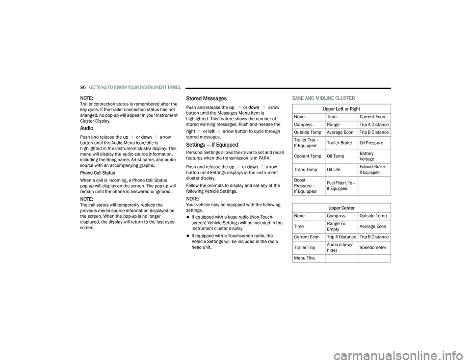
BASE AND MIDLINE CLUSTER
Upper Left or Right
None Time Current Econ
Compass Range Trip A Distance
Outside Temp Average Econ Trip B Distance
Trailer Trip –
If Equipped Trailer Brake Oil Pressure
Coolant Temp Oil Temp Battery
Voltage
Trans Temp Oil Life
Exhaust Brake –
If Equipped
Boost
Pressure –
If Equipped
Fuel Filter Life –
If Equipped
Upper Center
None Compass Outside Temp
Time Range To
EmptyAverage Econ
Current Econ Trip A Distance Trip B Distance
Trailer Trip Audio (show/
hide)Speedometer
Menu Title
23_DPF_OM_EN_USC_t.book Page 96
Page 99 of 444
GETTING TO KNOW YOUR INSTRUMENT PANEL97
Current Gear
Off
On
Odometer
No Decimal Point
Decimal Point
Defaults (Restores All Settings To Default Settings)
Cancel
Restore
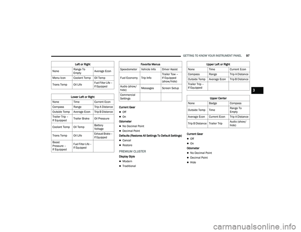
PREMIUM CLUSTER
Display Style
Modern
Traditional Current Gear
Off
On
Odometer
No Decimal Point
Decimal Point
Hide
Left or Right
None Range To
EmptyAverage Econ
Menu Icon Coolant Temp Oil Temp
Trans Temp Oil Life
Fuel Filter Life –
If Equipped
Lower Left or Right
None Time Current Econ
Compass Range Trip A Distance
Outside Temp Average Econ Trip B Distance
Trailer Trip –
If Equipped Trailer Brake Oil Pressure
Coolant Temp Oil Temp Battery
Voltage
Trans Temp Oil Life
Exhaust Brake –
If Equipped
Boost
Pressure –
If Equipped
Fuel Filter Life –
If Equipped
Favorite Menus
Speedometer Vehicle Info Driver Assist
Fuel Economy Trip Info Trailer Tow –
If Equipped
(show/hide)
Audio (show/
hide) Messages Screen Setup
Commercial
SettingsUpper Left or Right
None Time Current Econ
Compass Range Trip A Distance
Outside Temp Average Econ Trip B Distance
Trailer Trip –
If Equipped
Upper Center
None Badge Compass
Outside Temp Time Range To
Empty
Average Econ Current Econ Trip A Distance
Trip B Distance Trailer Trip Audio (show/
hide)
3
23_DPF_OM_EN_USC_t.book Page 97
Page 100 of 444
98GETTING TO KNOW YOUR INSTRUMENT PANEL
Fuel Gauge
Hide Range
Show Range
Defaults (Restores All Settings To Default Settings)
Restore
Cancel
Commercial Settings — If Equipped
Commercial Settings allows the driver to set and
recall additional features when the transmission is
in PARK.
Push and release the up or down arrow
button until Commercial Settings displays in the
instrument cluster display.
Follow the prompts to enter the required PIN and
enter the Commercial Settings submenu.
NOTE:If your vehicle is equipped with a touchscreen
radio, “Commercial Settings” will replace “Vehicle
Settings” in the instrument cluster display. The
Commercial Settings menu will only include the
settings below Ú page 199. Commercial Settings allows you to access the
following features (if equipped):
Power Take Off (PTO)
Remote Ignition
Idle Control
Backup Alarm
ParkSense
Aux Switches
PIN Setup
NOTE:If the vehicle’s PIN is forgotten or not known, see
an authorized dealer to have the PIN reset.
DIESEL MESSAGES AND WARNINGS
Diesel Particulate Filter (DPF) Messages
The Cummins® diesel engine meets all diesel
emissions standards, resulting in one of the lowest
emitting diesel engines ever produced. To achieve
these emissions standards, your vehicle is
equipped with a state-of-the-art engine and
exhaust system. These systems are seamlessly
integrated into your vehicle and managed by the
Powertrain Control Module (PCM). The PCM
manages engine combustion to allow the exhaust
system’s catalyst to trap and burn Particulate
Matter (PM) pollutants, with no input or interaction
on your part.
Your vehicle has the ability to alert you to
additional maintenance required on your vehicle or
engine. The following messages may display in
your instrument cluster display:
Perform Service
— Your vehicle will require emis -
sions maintenance at a set interval. To help
remind you when this maintenance is due, the
instrument cluster display will display “Perform
Service”. When the “Perform Service” message
is displayed in the instrument cluster display it is
necessary to have the emissions maintenance
performed. Emissions maintenance may
include replacing the Closed Crankcase Ventila -
tion (CCV) filter element. The procedure for
clearing and resetting the "Perform Service"
indicator message is located in the appropriate
Service Information.
Favorite Menus
Trip Info Navigation Off Road
Trailer Tow –
If Equipped
(show/hide) Audio (show/
hide)
WARNING!
A hot exhaust system can start a fire if you park
over materials that can burn. Such materials
might be grass or leaves coming into contact
with your exhaust system. Do not park or
operate your vehicle in areas where your
exhaust system can contact anything that can
burn.
23_DPF_OM_EN_USC_t.book Page 98
Page 111 of 444

GETTING TO KNOW YOUR INSTRUMENT PANEL109
Snowplow Mode Indicator Light —
If Equipped
This indicator light will illuminate when
Snowplow mode has been activated
Úpage 192.
Cold Ambient Derate Mode Indicator Light —
If Equipped
This indicator light will illuminate when a
derate (engine power reduction) is
activated for protection of the
turbocharger in cold ambient
temperatures.
Diesel Exhaust Brake Indicator Light —
If Equipped
This indicator light will illuminate when
the Diesel Exhaust Brake has been
activated, and is in full strength mode
Ú page 129.
4WD Lock Indicator Light
This light alerts the driver that the vehicle
is in the 4WD Lock mode. The front and
rear driveshafts are mechanically locked
together, forcing the front and rear
wheels to rotate at the same speed Ú page 140.
4WD Low Indicator Light — If Equipped
This light alerts the driver that the vehicle
is in the 4WD Low mode. The front and
rear driveshafts are mechanically locked
together forcing the front and rear
wheels to rotate at the same speed. Low range
provides a greater gear reduction ratio to provide
increased torque at the wheels Ú page 140.
4WD High Indicator Light — If Equipped
This light alerts the driver that the vehicle
is in the 4WD High mode. The front and
rear driveshafts are mechanically locked
together forcing the front and rear
wheels to rotate at the same speed.
NEUTRAL Indicator Light — If Equipped
This light alerts the driver that the 4WD
power transfer case is in the NEUTRAL
mode and the front and rear driveshafts
are disengaged from the powertrain.
Low Diesel Exhaust Fluid (DEF) Indicator
Light — If Equipped
The Low DEF Indicator will illuminate if
the vehicle is low on DEF Ú page 364.
Wait To Start Indicator Light — If Equipped
This indicator light will illuminate for
approximately two seconds when the
ignition is turned to the RUN position. Its
duration may be longer based on colder
operating conditions. Vehicle will not initiate start
until telltale is no longer displayed Ú page 117.
NOTE:The Wait To Start Indicator Light may not illuminate
if the intake manifold temperature is warm
enough.
Water In Fuel Indicator Light — If Equipped
The Water In Fuel Indicator Light will
illuminate when there is water detected
in the fuel filter. If this light remains on,
DO NOT start the vehicle before you drain
the water from the fuel filter to prevent engine
damage Ú page 360.
GREEN INDICATOR LIGHTS
Adaptive Cruise Control (ACC) Set With
Target Indicator Light — If Equipped
This will display when the ACC is set and
a the vehicle in front is detected
Úpage 150.
3
23_DPF_OM_EN_USC_t.book Page 109
Page 121 of 444

STARTING AND OPERATING119
3. While the Wait To Start Indicator Light is on, the instrument cluster will additionally display
a gauge or bar whose initial length represents
the full "Wait to Start" time period. Its length
will decrease until it disappears when the
"Wait to Start" time has elapsed.
4. After the engine Wait To Start Indicator Light goes off, the engine will automatically crank.
5. After engine start-up, check to see that there is oil pressure.
6. Release the parking brake and drive.
NOTE:
Engine idle speed will automatically increase to
1,000 RPM and engage the Variable Geometry
Turbocharger at low coolant temperatures to
improve engine warm-up.
The engine will not automatically crank after the
engine Wait To Start Indicator Light goes off if a
door or the hood is ajar.
If the engine stalls, or if the ignition switch is left
ON for more than two minutes after the Wait To
Start Indicator Light goes out, reset the intake
air heater by turning the ignition switch to the
OFF position for at least 5 seconds and then
back ON. Repeat steps 1 through 6 of “Keyless
Enter ‘n Go™ Starting Procedure – Engine Mani -
fold Air Temperature 0°F To 66°F (–18°C to
19°C).”
EXTREME COLD WEATHER
The Cummins® Turbo Diesel engine is equipped
with several features designed to assist cold
weather starting and operation:
The engine block heater is a resistance heater
installed in the water jacket of the engine just
above and behind the oil filter. It requires a
110–115 Volt AC electrical outlet with a
grounded, three-wire extension cord.
NOTE:The engine block heater cord is a factory installed
option. If your vehicle is not equipped, heater cords
are available from an authorized Mopar® dealer.
A 12 Volt heater built into the fuel filter housings
aid in preventing fuel gelling. It is controlled by a
built-in thermostat.
An intake air heater system both improves
engine starting and reduces the amount of
white smoke generated by a warming engine.
NORMAL STARTING PROCEDURE —
E
NGINE MANIFOLD AIR TEMPERATURE
A
BOVE 66°F (19°C)
Observe the instrument panel cluster lights when
starting the engine.
1. Always apply the parking brake.
2. Shift into PARK for an automatic transmission.
3. Place the ignition switch in the ON/RUN
position and watch the instrument panel
cluster lights.
CAUTION!
If the Water in Fuel Indicator Light remains on,
DO NOT START the engine before you drain the
water from the fuel filters to avoid engine
damage Ú page 360.
CAUTION!
Do not crank engine for more than 25 seconds
at a time or starter motor damage may result.
Turn the ignition switch to the OFF position and
wait at least two minutes for the starter to cool
before repeating start procedure.
CAUTION!
If the Water in Fuel Indicator Light remains on,
DO NOT START the engine before you drain the
water from the fuel filters to avoid engine
damage Úpage 360.
4
23_DPF_OM_EN_USC_t.book Page 119
Page 122 of 444

120STARTING AND OPERATING
4. Place the ignition switch in the START position and crank the engine. Do not press the
accelerator during starting.
5. Check that the Oil Pressure Warning Light has turned off.
6. Release the parking brake.
STARTING PROCEDURE — ENGINE
M
ANIFOLD AIR TEMPERATURE 0°F TO
66°F (–18°C
TO 19°C)
NOTE:The temperature displayed in the instrument
cluster does not necessarily reflect the engine
manifold air temperature Ú page 89. When
engine temperatures fall below 66°F (19°C) the
Wait To Start Indicator Light will remain on indi -
cating the intake air heater system is active. Follow the steps in the “Normal Starting”
procedure except:
1. The Wait To Start Indicator Light will remain
on for a period of time that varies depending
on the engine temperature.
2. While the Wait To Start Indicator Light is on, the instrument cluster will additionally display
a gauge or bar whose initial length represents
the full “Wait to Start” time period. Its length
will decrease until it disappears when the
“Wait to Start” time has elapsed.
3. After the Wait To Start Indicator Light goes off, place the ignition switch in the START position.
Do not press the accelerator during starting. 4. After engine start-up, check that the Oil
Pressure Warning Light has turned off.
5. Release the parking brake and drive.
NOTE:
Engine idle speed will automatically increase to
1,000 RPM and engage the Variable Geometry
Turbocharger at low coolant temperatures to
improve engine warm-up.
Automatic equipped vehicles with optional
Keyless Enter ‘n Go™ – If the ENGINE START/
STOP button is pushed once while in PARK with
the ignition off and driver’s foot on the brake
pedal, the vehicle will automatically crank and
start after the “Wait to Start” time has elapsed.
If it is desired to abort the start process before it
completes, the driver’s foot should be fully
removed from the brake pedal prior to pushing
the start button again in order for the ignition to
move directly to off.
If the engine stalls, or if the ignition switch is left
on for more than two minutes after the Wait To
Start Indicator Light goes out, reset the intake
air heater by turning the ignition switch to the
OFF position for at least five seconds and then
back to the ON/RUN position. Repeat steps 1
through 5 of “Starting Procedure – Engine Mani -
fold Air Temperature 0°F To 66°F (–18°C to
19°C).”
CAUTION!
Do not crank engine for more than 25 seconds
at a time or starter motor damage may result.
Turn the ignition switch to the OFF position and
wait at least two minutes for the starter to cool
before repeating start procedure.
CAUTION!
If the Water in Fuel Indicator Light remains on,
DO NOT START the engine before you drain the
water from the fuel filters to avoid engine
damage Ú page 360.
CAUTION!
Do not crank engine for more than 25 seconds
at a time or starter motor damage may result.
Turn the ignition switch to the OFF position and
wait at least two minutes for the starter to cool
before repeating start procedure.
23_DPF_OM_EN_USC_t.book Page 120
Page 126 of 444

124STARTING AND OPERATING
ENGINE IDLING
Avoid prolonged idling. Long periods of idling may be
harmful to your engine because combustion
chamber temperatures can drop so low that the fuel
may not burn completely. Incomplete combustion
allows carbon and varnish to form on piston rings,
engine valves, and injector nozzles. Also, the
unburned fuel can enter the crankcase, diluting the
oil and causing rapid wear to the engine.
If the engine is allowed to idle or the truck is driven
on low engine speed drive cycles for more than two
hours, the system will automatically enter an
emissions operating mode that will increase the
engine idle speed to 900 RPM (1,050 RPM for
Chassis Cab). While in this mode, which is
designed to help maintain the Diesel Particulate
Filter, the engine idle speed will return to normal
when the brake pedal is applied. A small change in
engine tone or a slight change in engine
performance while accelerating may also be
noticeable at speeds below 20 mph (32 km/h).
This operating mode may last for up to an hour of
idle time, or around 20 minutes of driving time.
Your truck may have been ordered with an optional
voltage monitoring idle up feature. If a load is placed
on the electrical system while the truck is in PARK,
this feature will attempt to maintain normal system
voltage by automatically increasing engine idle
speed. You may notice several consecutive increases
in idle speed, up to a maximum of 1,450 RPM, as the system will attempt to utilize the smallest increase in
idle speed necessary to maintain normal system
voltage. The idle speed will return to normal when
either the electrical load is removed, or when the
brake pedal is applied.
NOTE:For instrument cluster display messages related to
the vehicle's exhaust system Ú
page 89.
Idle-Up Feature
The driver-controlled high idle speed feature will
help increase cylinder temperatures and provide
additional cab heat, however, excessive idling may
still cause the exhaust after-treatment system to
not properly regenerate. Extended periods of idle
time should be avoided.
The Idle-Up feature uses the Cruise Control buttons
to increase engine idle speed and quickly warm the
vehicle's interior.
1. With the transmission in PARK, the parking
brake applied, and the engine running, turn
on the Cruise Control, then push the SET (-)
button.
2. The engine RPM will go up to 1,100 RPM. To increase the RPM, push and hold the RES (+)
button and the idle speed will increase to
approximately 1,500 RPM. To decrease the
RPM, push and hold the SET (-) button and the
idle speed will decrease to approximately
1,100 RPM. 3. To cancel the Idle–Up feature, either push the
CANCEL button, push the ON/OFF button, or
press the brake pedal.
NOISE
Diesel engines can create noises that may seem
as a concern. The nature of a diesel engine is
compression ignition where compressed air and
fuel are mixed and ignited. Weather, barometric
pressure, altitude and temperature will affect how
fuel is ignited in the engine. Engines will sound
different from day to day or previous model years.
Clicking, ticking, or light knocking is normal and will
change from day to day, as the engine breaks in,
and can vary with changes in ambient
temperature; this is normal. Diesel equipped
vehicles also have an exhaust after treatment
system to reduce emissions utilizing a Diesel
Particulate Filter (DPF) and a Selective Reduction
Catalyst (SCR). The SCR reduces Nox using the
Diesel Exhaust Fluid (DEF) system. DEF is injected
directly into the SCR through an dosing module.
This process will create a clicking sound and at
times, will make noise even with the vehicle shut
off. This is normal as the DEF dosing module is
purging DEF. If at any time the check engine light is
on, please visit an authorized dealer.
23_DPF_OM_EN_USC_t.book Page 124
Page 129 of 444

STARTING AND OPERATING127
DIESEL PARTICULATE FILTER (DPF)
M
ANUAL REGENERATION — IF EQUIPPED
On equipped Chassis Cabs, a manual regeneration
can be enable through the instrument cluster. The
manual regeneration will allow the DPF to
complete a regeneration, lowering the soot level
without having to drive the vehicle. The vehicle
must be in PARK to access this feature, and the
fuel level must be over 12.5% full. A message
displaying the time left on the regeneration will
appear on the instrument cluster, and the
instrument cluster will display the soot level
Ú page 89.
ENGINE BLOCK HEATER — IF EQUIPPED
The engine block heater warms the engine, and
permits quicker starts in cold weather. Connect the
cord to a standard 110-115 Volt AC electrical
outlet with a grounded, three-wire extension cord.
The engine block heater cord is routed behind the
front bumper and accessible through the right hole
of the air dam.
The engine block heater must be plugged in at
least one hour to have an adequate warming effect
on the engine. It includes a removable cap that is secured by a
tethered strap. It also has a c-clip that is used for
storage when not in use for the Winter months.
During Winter months, remove the heater cord
wiring assembly from itself on the c-clip.
NOTE:The block heater will require 110 Volt AC and
6.5 Amps to activate the heater element.
Block Heater Usage
For ambient temperatures below 0°F (-18°C),
engine block heater usage is recommended.
For ambient temperatures below –20°F (-29°C),
engine block heater usage is required.
ENGINE BREAK-IN RECOMMENDATIONS—
GASOLINE ENGINE
A long break-in period is not required for the engine
and drivetrain (transmission and axle) in your
vehicle.
Drive moderately during the first 300 miles
(500 km). After the initial 60 miles (100 km),
speeds up to 50 or 55 mph (80 or 90 km/h) are
desirable. While cruising, brief full-throttle acceleration within
the limits of local traffic laws contributes to a good
break-in. Wide-open throttle acceleration in low
gear can be detrimental and should be avoided.
The engine oil installed in the engine at the factory
is a high-quality energy conserving type lubricant.
Oil changes should be consistent with anticipated
climate conditions under which vehicle operations
will occur. For the recommended viscosity and
quality grades Ú
page 419.
NOTE:A new engine may consume some oil during its first
few thousand miles (kilometers) of operation. This
should be considered a normal part of the break-in
and not interpreted as a problem. Please check
your oil level with the engine oil indicator often
during the break in period. Add oil as required.
CAUTION!
Never use Non-Detergent Oil or Straight Mineral
Oil in the engine or damage may result.
4
23_DPF_OM_EN_USC_t.book Page 127