fuse Ram ProMaster 2014 User Guide
[x] Cancel search | Manufacturer: RAM, Model Year: 2014, Model line: ProMaster, Model: Ram ProMaster 2014Pages: 410, PDF Size: 2.83 MB
Page 360 of 410
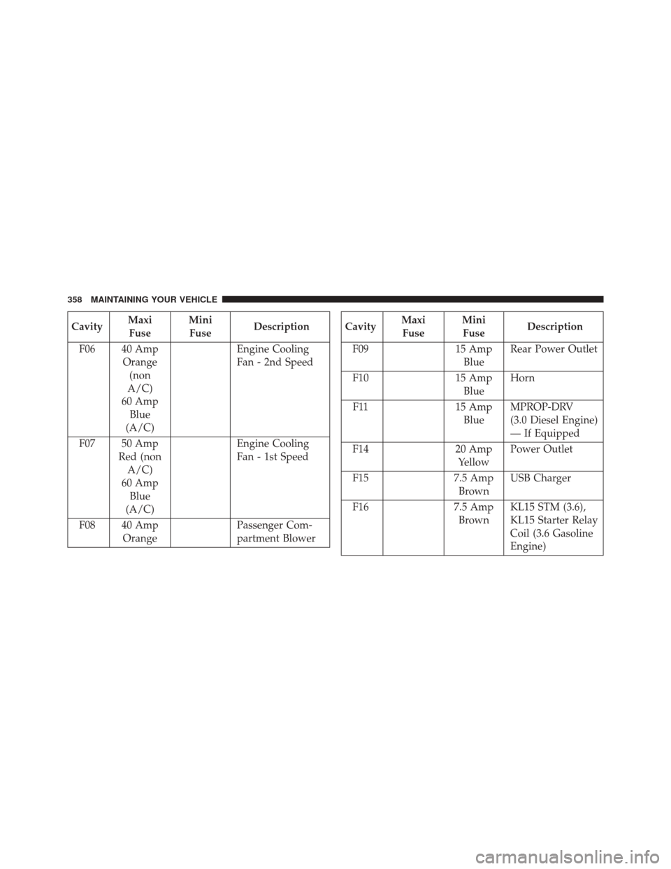
CavityMaxi
Fuse Mini
Fuse Description
F06 40 Amp Orange(non
A/C)
60 Amp Blue
(A/C) Engine Cooling
Fan - 2nd Speed
F07 50 Amp Red (nonA/C)
60 Amp Blue
(A/C) Engine Cooling
Fan - 1st Speed
F08 40 Amp Orange Passenger Com-
partment BlowerCavity
Maxi
Fuse Mini
Fuse Description
F09 15 Amp BlueRear Power Outlet
F10 15 Amp BlueHorn
F11 15 Amp
Blue MPROP-DRV
(3.0 Diesel Engine)
— If Equipped
F14 20 Amp
Yellow Power Outlet
F15 7.5 Amp
Brown USB Charger
F16 7.5 Amp
Brown KL15 STM (3.6),
KL15 Starter Relay
Coil (3.6 Gasoline
Engine)
358 MAINTAINING YOUR VEHICLE
Page 361 of 410
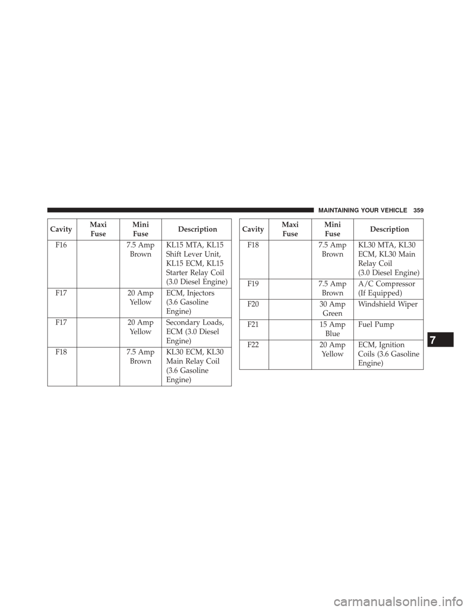
CavityMaxi
Fuse Mini
Fuse Description
F16 7.5 Amp BrownKL15 MTA, KL15
Shift Lever Unit,
KL15 ECM, KL15
Starter Relay Coil
(3.0 Diesel Engine)
F17 20 Amp YellowECM, Injectors
(3.6 Gasoline
Engine)
F17 20 Amp YellowSecondary Loads,
ECM (3.0 Diesel
Engine)
F18 7.5 Amp
Brown KL30 ECM, KL30
Main Relay Coil
(3.6 Gasoline
Engine)Cavity
Maxi
Fuse Mini
Fuse Description
F18 7.5 Amp BrownKL30 MTA, KL30
ECM, KL30 Main
Relay Coil
(3.0 Diesel Engine)
F19 7.5 Amp BrownA/C Compressor
(If Equipped)
F20 30 Amp GreenWindshield Wiper
F21 15 Amp BlueFuel Pump
F22 20 Amp YellowECM, Ignition
Coils (3.6 Gasoline
Engine)
7
MAINTAINING YOUR VEHICLE 359
Page 362 of 410
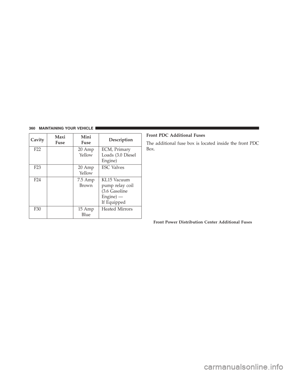
CavityMaxi
Fuse Mini
Fuse Description
F22 20 Amp YellowECM, Primary
Loads (3.0 Diesel
Engine)
F23 20 Amp
Yellow ESC Valves
F24 7.5 Amp
Brown KL15 Vacuum
pump relay coil
(3.6 Gasoline
Engine) —
If Equipped
F30 15 Amp
Blue Heated Mirrors Front PDC Additional Fuses
The additional fuse box is located inside the front PDC
Box.
Front Power Distribution Center Additional Fuses
360 MAINTAINING YOUR VEHICLE
Page 363 of 410
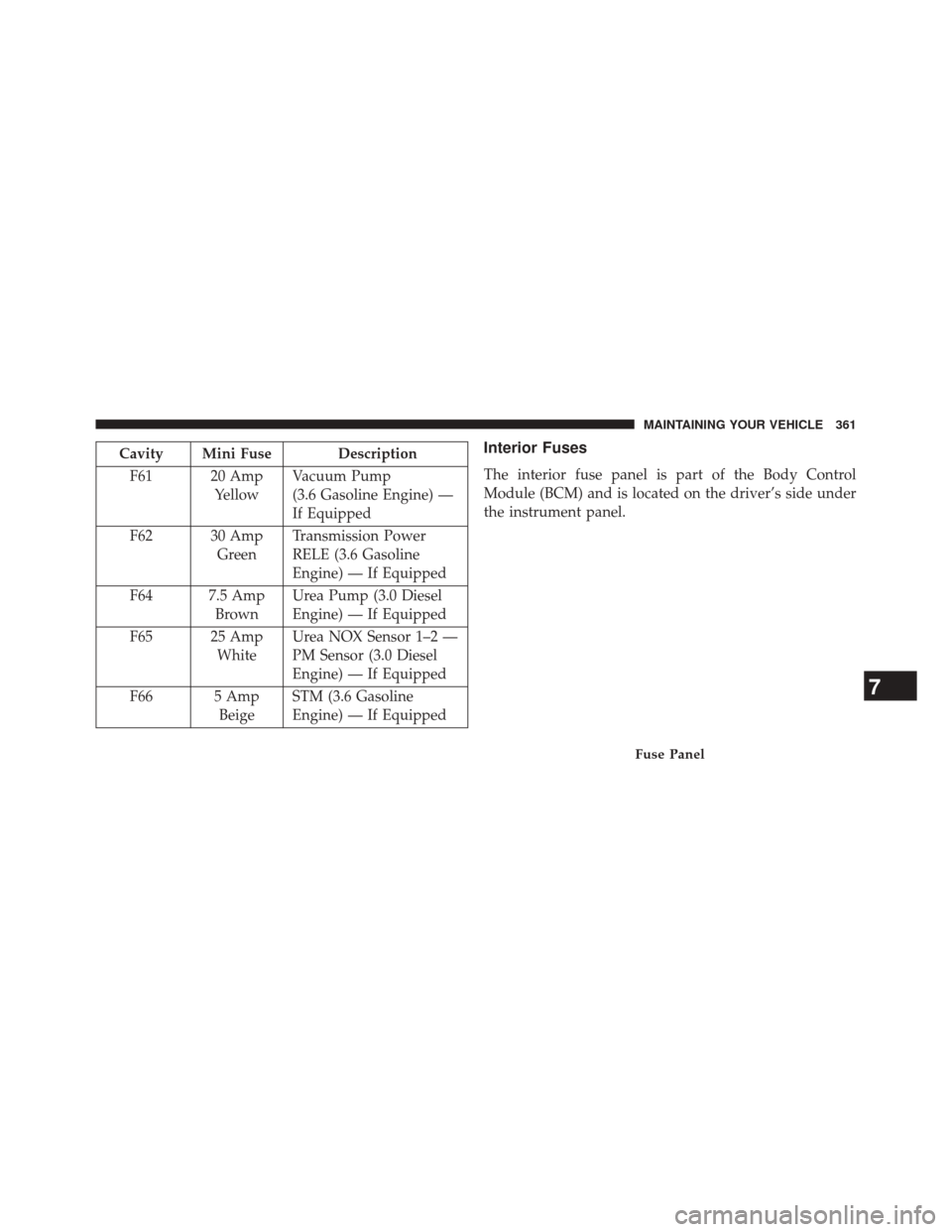
Cavity Mini Fuse DescriptionF61 20 Amp YellowVacuum Pump
(3.6 Gasoline Engine) —
If Equipped
F62 30 Amp GreenTransmission Power
RELE (3.6 Gasoline
Engine) — If Equipped
F64 7.5 Amp BrownUrea Pump (3.0 Diesel
Engine) — If Equipped
F65 25 Amp WhiteUrea NOX Sensor 1–2 —
PM Sensor (3.0 Diesel
Engine) — If Equipped
F66 5 Amp BeigeSTM (3.6 Gasoline
Engine) — If EquippedInterior Fuses
The interior fuse panel is part of the Body Control
Module (BCM) and is located on the driver’s side under
the instrument panel.
Fuse Panel
7
MAINTAINING YOUR VEHICLE 361
Page 364 of 410
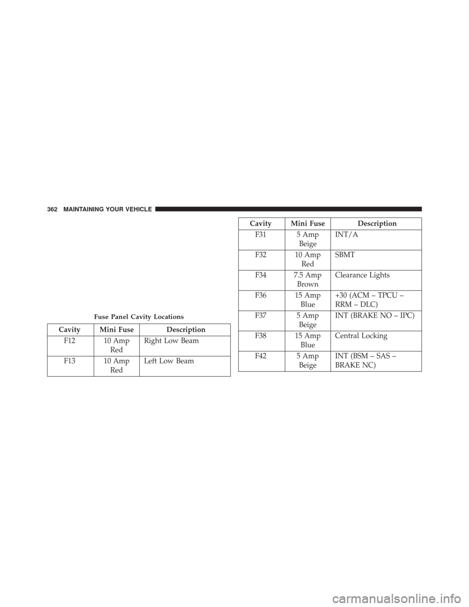
Cavity Mini Fuse DescriptionF12 10 Amp RedRight Low Beam
F13 10 Amp RedLeft Low Beam
Cavity Mini Fuse Description
F31 5 Amp BeigeINT/A
F32 10 Amp RedSBMT
F34 7.5 Amp BrownClearance Lights
F36 15 Amp Blue+30 (ACM – TPCU –
RRM – DLC)
F37 5 Amp BeigeINT (BRAKE NO – IPC)
F38 15 Amp BlueCentral Locking
F42 5 Amp BeigeINT (BSM – SAS –
BRAKE NC)
Fuse Panel Cavity Locations
362 MAINTAINING YOUR VEHICLE
Page 365 of 410
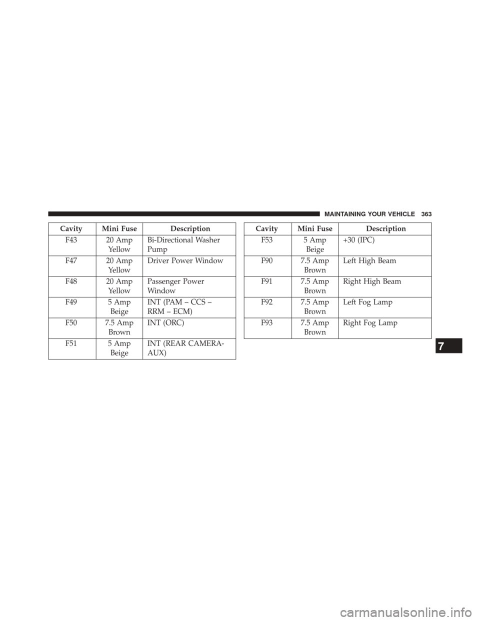
Cavity Mini Fuse DescriptionF43 20 Amp YellowBi-Directional Washer
Pump
F47 20 Amp YellowDriver Power Window
F48 20 Amp YellowPassenger Power
Window
F49 5 Amp BeigeINT (PAM – CCS –
RRM – ECM)
F50 7.5 Amp BrownINT (ORC)
F51 5 Amp BeigeINT (REAR CAMERA-
AUX)Cavity Mini Fuse Description
F53 5 Amp Beige+30 (IPC)
F90 7.5 Amp BrownLeft High Beam
F91 7.5 Amp BrownRight High Beam
F92 7.5 Amp BrownLeft Fog Lamp
F93 7.5 Amp BrownRight Fog Lamp
7
MAINTAINING YOUR VEHICLE 363
Page 366 of 410
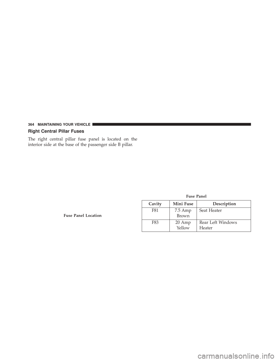
Right Central Pillar Fuses
The right central pillar fuse panel is located on the
interior side at the base of the passenger side B pillar.
Cavity Mini Fuse DescriptionF81 7.5 Amp BrownSeat Heater
F83 20 Amp YellowRear Left Windows
Heater
Fuse Panel Location
Fuse Panel
364 MAINTAINING YOUR VEHICLE
Page 367 of 410

Cavity Mini Fuse DescriptionF84 20 Amp YellowRear Right Windows
Heater
F85 10 Amp RedRear Heater Prep
VEHICLE STORAGE
If you are leaving your vehicle dormant for more than 21
days, you may want to take these steps to protect your
battery.
•
Disconnect the negative cable from the battery.
• Anytime you store your vehicle, or keep it out of
service (e.g., vacation) for two weeks or more, run the
air conditioning system at idle for about five minutes
in the fresh air and high blower setting. This will
ensure adequate system lubrication to minimize the
possibility of compressor damage when the system is
started again.
REPLACEMENT BULBS
Interior Bulbs
Bulb Number
Overhead Lamp C5W
Sun Visors C5W
Courtesy Lamp FF500
Glove Compartment C5W
Rear Courtesy Lamp C5W
Exterior Bulbs
Bulb Number
Front Low and High Beam
Headlamp H7LL
Front Park/Turn Signal Lamps 7444NA
Daytime Running Lamps
(if equipped) 74407
MAINTAINING YOUR VEHICLE 365
Page 399 of 410
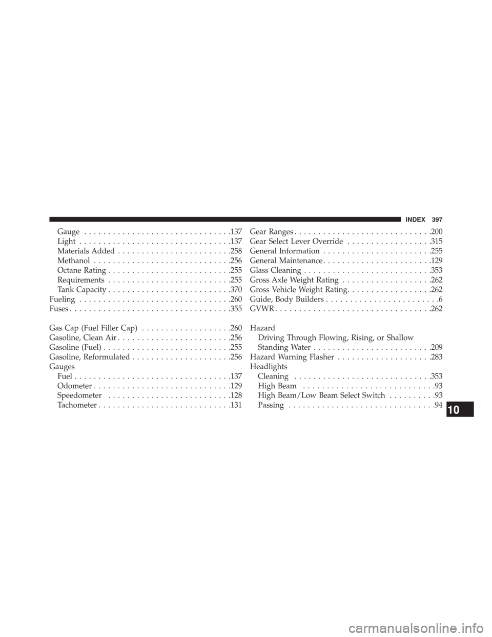
Gauge.............................. .137
Light ............................... .137
Materials Added ....................... .258
Methanol ............................ .256
Octane Rating ......................... .255
Requirements ......................... .255
Tank Capacity ......................... .370
Fueling ............................... .260
Fuses ................................. .355
Gas Cap (Fuel Filler Cap) ...................260
Gasoline, Clean Air ....................... .256
Gasoline (Fuel) .......................... .255
Gasoline, Reformulated .....................256
Gauges Fuel ................................ .137
Odometer ............................ .129
Speedometer ......................... .128
Tachometer ........................... .131Gear Ranges
............................ .200
Gear Select Lever Override ..................315
General Information ...................... .255
General Maintenance ...................... .129
Glass Cleaning .......................... .353
Gross Axle Weight Rating ...................262
Gross Vehicle Weight Rating ..................262
Guide, Body Builders ........................6
GVWR ................................ .262
Hazard Driving Through Flowing, Rising, or Shallow
Standing Water ........................ .209
Hazard Warning Flasher ....................283
Headlights Cleaning ............................ .353
High Beam ............................93
High Beam/Low Beam Select Switch ..........93
Passing ...............................94
10
INDEX 397