ECO mode Ram ProMaster 2018 Owner's Manual
[x] Cancel search | Manufacturer: RAM, Model Year: 2018, Model line: ProMaster, Model: Ram ProMaster 2018Pages: 337, PDF Size: 4.13 MB
Page 6 of 337
INTRODUCTION
Dear Customer,
Congratulations on selecting your new vehicle. Be assured
that it represents precision workmanship, distinctive styl-
ing, and high quality. This Owner ’s Manual has been
prepared with the assistance of service and engineering
specialists to acquaint you with the operation and mainte-
nance of your vehicle. It is supplemented by Warranty
Information, and customer oriented documents. In the
attached Warranty Booklet, you will find a description of
the services that FCA offers to its customers, the Warranty
Certificate and the details of the terms and conditions for
maintaining its validity. Please take the time to read all of
these publications carefully before driving your vehicle for
the first time. Following the instructions, recommenda-
tions, tips, and important warnings in this manual will
help assure safe and enjoyable operation of your vehicle.
Be sure you are familiar with all vehicle controls, particu-
larly those used for braking, steering, transmission, and
transfer case shifting (if equipped). Learn how your vehicle
handles on different road surfaces. Your driving skills will
improve with experience.
This Owner ’s Manual describes all versions of this vehicle.
Options and equipment dedicated to specific markets orversions are not expressly indicated in the text. Therefore,
you should only consider the information which is related
to the trim level, engine, and version that you have
purchased. Any content introduced throughout the Own-
er ’s Information, that may or may not be applicable to your
vehicle, will be identified with the wording “If Equipped”.
All data contained in this publication are intended to help
you use your vehicle in the best possible way. FCA aims at
a constant improvement of the vehicles produced. For this
reason, it reserves the right to make changes to the model
described for technical and/or commercial reasons. For
further information, contact an authorized dealer.
NOTE:
After reviewing the Owner ’s Information, it should
be stored in the vehicle for convenient referencing, and
remain with the vehicle when sold.
When it comes to service, remember that your authorized
dealer knows your vehicle best, has factory-trained techni-
cians and genuine MOPAR® parts, and cares about your
satisfaction.
HOW TO USE THIS MANUAL
Essential Information
Consult the Table of Contents to determine which section
contains the information you desire.
4 INTRODUCTION
Page 31 of 337
the right position and the first vehicle movement after the
cranking is attempted, a chime and a text message will
appear in instrument cluster display. Rotate and lock the
swivel seats in the correct position before trying again.
If the driver or the passenger seats are not locked in facing
forward position during movement of the vehicle, a mes-
sage will appear in the instrument cluster display and an
intermittent chime will sound until key-off or until the
swivel seats are locked in facing forward position. Stop and
move the swivel seats in the correct position before pro-
ceeding.
If a fault is present in the system and it is not possible to
check the correct position of the swivel seats, a message
and the generic warning light appears in the instrument
cluster display to inform about the failure. In these condi-
tions, check the status of the swivel seats and not drive the
vehicle until the swivel seats are locked in facing forward
position.Heated Seats — If Equipped
On some models, the front driver and passenger seats may
be equipped with heaters in both the seat cushions and
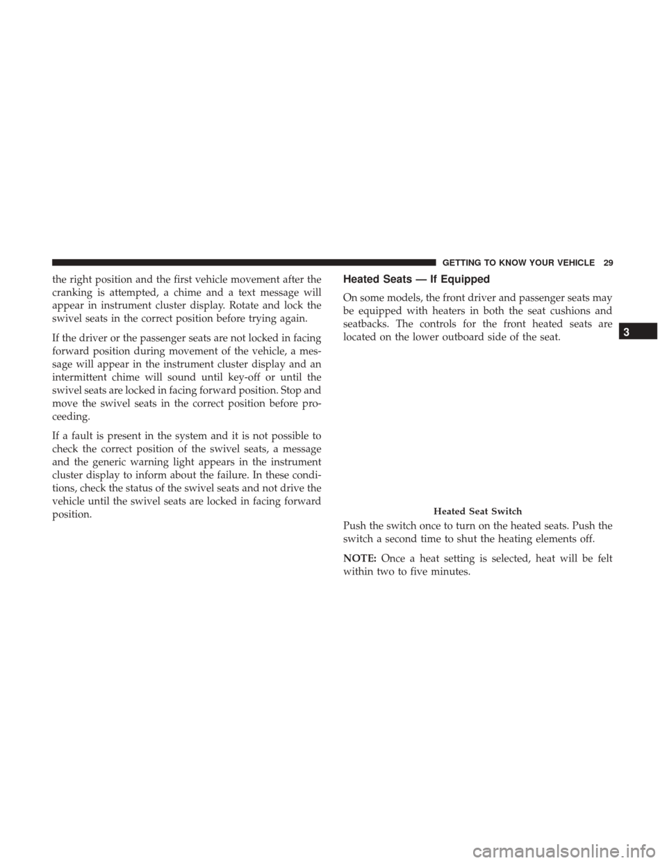
seatbacks. The controls for the front heated seats are
located on the lower outboard side of the seat.
Push the switch once to turn on the heated seats. Push the
switch a second time to shut the heating elements off.
NOTE:Once a heat setting is selected, heat will be felt
within two to five minutes.
Heated Seat Switch
3
GETTING TO KNOW YOUR VEHICLE 29
Page 46 of 337
Illuminated Entry
The courtesy lights will turn on when you use the key fob
or manually from the driver door cylinder to unlock the
doors or open any door.
The lights will fade to off after approximately 30 seconds,
or they will immediately fade to off once the ignition
switch is turned to ON/RUN from the OFF position.
NOTE:
•The front courtesy overhead console and door courtesy
lights will not turn off if the dimmer control is in the
“Dome ON” position.
• The illuminated entry system will not operate if the
dimmer control is in the “Dome OFF” position.
WIPERS AND WASHERS
Front Wiper Operation
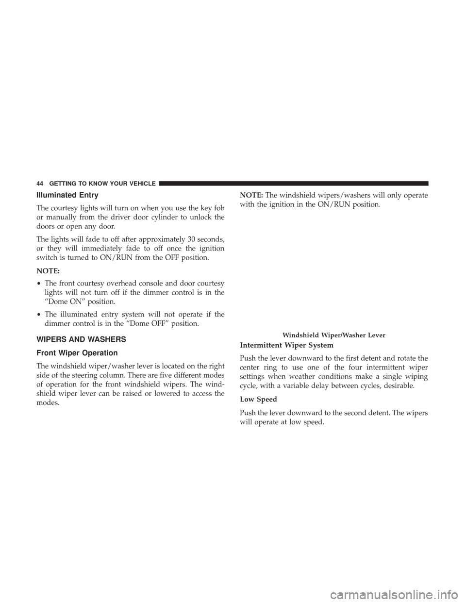
The windshield wiper/washer lever is located on the right
side of the steering column. There are five different modes
of operation for the front windshield wipers. The wind-
shield wiper lever can be raised or lowered to access the
modes. NOTE:
The windshield wipers/washers will only operate
with the ignition in the ON/RUN position.
Intermittent Wiper System
Push the lever downward to the first detent and rotate the
center ring to use one of the four intermittent wiper
settings when weather conditions make a single wiping
cycle, with a variable delay between cycles, desirable.
Low Speed
Push the lever downward to the second detent. The wipers
will operate at low speed.
Windshield Wiper/Washer Lever
44 GETTING TO KNOW YOUR VEHICLE
Page 49 of 337

IconDescription
Recirculation Button
Press and release this button to change the system between recirculation mode and outside air
mode. Recirculation can be used when outside conditions such as smoke, odors, dust, or high
humidity are present.
NOTE:
•Continuous use of the Recirculation mode may make the inside air stuffy and window fog-
ging may occur. Extended use of this mode is not recommended.
•The use of the Recirculation mode in cold or damp weather could cause windows to fog on
the inside, because of moisture buildup inside the vehicle. Select the outside air position for
maximum defogging.
•Recirculation can be used in all modes except for Defrost.
•The A/C can be deselected manually without disturbing the mode control selection.
Front Defrost Mode
Turn the Knob to the Front Defrost position. Air comes from the windshield and side window
demist outlets. When the defrost button is selected, the blower level will increase. Use Defrost
mode with maximum temperature settings for best windshield and side window defrosting and
defogging.
Rear Defrost Button
Push and release the Rear Defrost Control button to turn ON the rear window defroster and the
heated outside mirrors (if equipped). An indicator will illuminate when the rear window de-
froster is ON. The rear window defroster automatically turns OFF after ten minutes.
3
GETTING TO KNOW YOUR VEHICLE 47
Page 52 of 337
Additional Rear Climate Control — If Equipped
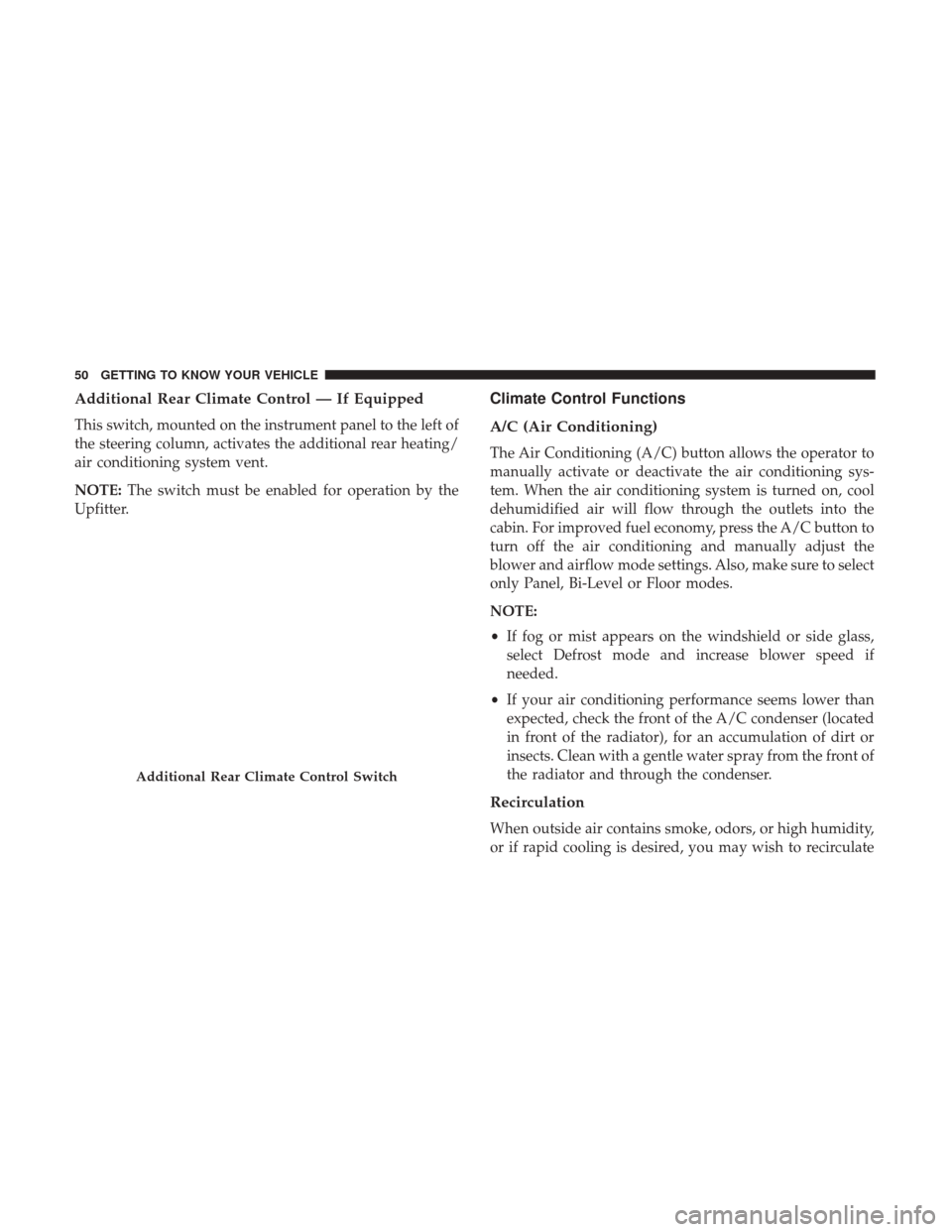
This switch, mounted on the instrument panel to the left of
the steering column, activates the additional rear heating/
air conditioning system vent.
NOTE:The switch must be enabled for operation by the
Upfitter.
Climate Control Functions
A/C (Air Conditioning)
The Air Conditioning (A/C) button allows the operator to
manually activate or deactivate the air conditioning sys-
tem. When the air conditioning system is turned on, cool
dehumidified air will flow through the outlets into the
cabin. For improved fuel economy, press the A/C button to
turn off the air conditioning and manually adjust the
blower and airflow mode settings. Also, make sure to select
only Panel, Bi-Level or Floor modes.
NOTE:
• If fog or mist appears on the windshield or side glass,
select Defrost mode and increase blower speed if
needed.
• If your air conditioning performance seems lower than
expected, check the front of the A/C condenser (located
in front of the radiator), for an accumulation of dirt or
insects. Clean with a gentle water spray from the front of
the radiator and through the condenser.
Recirculation
When outside air contains smoke, odors, or high humidity,
or if rapid cooling is desired, you may wish to recirculate
Additional Rear Climate Control Switch
50 GETTING TO KNOW YOUR VEHICLE
Page 53 of 337
interior air by pressing the Recirculation control button.
The recirculation indicator will illuminate when this button
is selected. Press the button a second time to turn off the
Recirculation mode and allow outside air into the vehicle.
NOTE:In cold weather, use of recirculation mode may lead
to excessive window fogging. On systems with Manual
Climate Controls, the Recirculation mode is not allowed in
Defrost mode to improve window clearing operation.
Recirculation will be disabled automatically if this mode is
selected. Attempting to use Recirculation while in this
mode will cause the LED in the control button to blink and
then turn off.
Operating Tips
NOTE: Refer to the chart at the end of this section for
suggested control settings for various weather conditions.
Summer Operation
The engine cooling system must be protected with a
high-quality antifreeze coolant to provide proper corrosion
protection and to protect against engine overheating. A
solution of 50% OAT (Organic Additive Technology) cool-
ant that meets the requirements of FCA Material Standard MS.90032 and 50% water is recommended. Refer to “Dealer
Service” in “Servicing And Maintenance” for proper cool-
ant selection.
Winter Operation
Use of the air Recirculation mode during winter months is
not recommended because it may cause window fogging.
Vacation Storage
Any time you store your vehicle or keep it out of service
(i.e., vacation) for two weeks or more, run the air condi-
tioning system at idle for about five minutes in the fresh air
and high blower setting. This will ensure adequate system
lubrication to minimize the possibility of compressor dam-
age when the system is started again.
Window Fogging
Interior fogging on the windshield can be quickly removed
by turning the mode selector to Defrost. The Defrost/Floor
mode can be used to maintain a clear windshield and
provide sufficient heating. If side window fogging be-
comes a problem increase blower speed. Vehicle windows
tend to fog on the inside in mild but rainy or humid
weather.
3
GETTING TO KNOW YOUR VEHICLE 51
Page 69 of 337
Instrument Cluster Descriptions
1. Speedometer•Indicates vehicle speed.
2. Instrument Cluster Display •When the appropriate conditions exist, this display
shows instrument cluster display messages. Refer to
“Instrument Cluster Display” in “Getting To Know
Your Instrument Panel” for further information.
• Odometer/Trip Odometer Display Area
U.S. Federal regulations require that upon transfer of
vehicle ownership, the seller certify to the purchaser
the correct mileage that the vehicle has been driven. If
your odometer needs to be repaired or serviced, the
repair technician should leave the odometer reading
the same as it was before the repair or service. If s/he
cannot do so, then the odometer must be set at zero,
and a sticker must be placed in the door jamb stating
what the mileage was before the repair or service. It is
a good idea for you to make a record of the odometer
reading before the repair/service, so that you can be
sure that it is properly reset, or that the door jamb
sticker is accurate if the odometer must be reset at zero. •
Gear Selector Status (PRND)
The gear selector status “P,R,N,D,1,2,3,4,5,6” are dis-
played indicating the gear selector position. Telltales
“1,2,3,4,5,6” indicate the manual mode has been en-
gaged and the gear selected is displayed. Refer to
“Automatic Transmission” in “Starting And Operat-
ing” for further information on ERS.
3. Tachometer •This gauge measures engine revolutions per minute
(RPM x 1000). Before the pointer reaches the red area,
ease up on the accelerator to prevent engine damage.
4. Temperature Gauge •The temperature gauge shows engine coolant tem-
perature. Any reading within the normal range indi-
cates that the engine cooling system is operating
satisfactorily.
• The gauge pointer will likely indicate a higher tem-
perature when driving in hot weather or up mountain
grades. It should not be allowed to exceed the upper
limits of the normal operating range.
4
GETTING TO KNOW YOUR INSTRUMENT PANEL 67
Page 72 of 337
•MODE Button
Push and hold the MODEbutton for a time longer than
one second to access/select the information screens or
submenu screens of a main menu item. Push and hold the
MODE button for two seconds to reset displayed/selected
features that can be reset.
• Up Arrow Button
Push and release the uparrow button to scroll
upward through the main menu and submenus
or adjust the illumination on the instrument
panel when the headlights are on.
• Down Arrow Button
Push and release the downarrow button to scroll
downward through the main menu and sub-
menus or adjust the illumination on the instru-
ment panel when the headlights are on.
Change Engine Oil
Your vehicle is equipped with an engine oil change indi-
cator system. The “Change Engine Oil” message will
display in the instrument cluster display. The engine oil change indicator system is duty cycle based, which means
the engine oil change interval may fluctuate, dependent
upon your personal driving style.
Unless reset, this message will continue to display each
time you turn the ignition switch to the ON/RUN position.
To turn off the message temporarily, push and release the
MODE
button. To reset the oil change indicator system
(after performing the scheduled maintenance), refer to the
following procedure.
1. Turn the ignition switch to the ON position (do not start the engine).
2. Fully push the accelerator pedal slowly, three times, within 10 seconds.
3. Turn the ignition switch to the OFF/LOCK position.
NOTE: If the indicator message illuminates when you
start the vehicle, the oil change indicator system did not
reset. If necessary, repeat this procedure.Display Setup Menu
The menu comprises a series of functions arranged in a
cycle. Push and release the upordown arrow button to
access the different options and settings (setup).
70 GETTING TO KNOW YOUR INSTRUMENT PANEL
Page 113 of 337

Supplemental Restraint Systems (SRS)
Some of the safety features described in this section may be
standard equipment on some models, or may be optional
equipment on others. If you are not sure, ask your autho-
rized dealer.
The air bag system must be ready to protect you in a
collision. The Occupant Restraint Controller (ORC) moni-
tors the internal circuits and interconnecting wiring asso-
ciated with the electrical Air Bag System Components.
Your vehicle may be equipped with the following Air Bag
System Components:
Air Bag System Components
•Occupant Restraint Controller (ORC)
• Air Bag Warning Light
•Steering Wheel and Column
• Instrument Panel
• Driver and Front Passenger Air Bags
• Seat Belt Buckle Switch
• Supplemental Side Air Bags
• Front and Side Impact Sensors •
Seat Belt Pretensioners
Air Bag Warning Light
The ORC monitors the readiness of the electronic parts of
the air bag system whenever the ignition switch
is in the AVV/START or MAR/ACC/ON/RUN
position. If the ignition switch is in the STOP/
OFF/LOCK position the air bag system is not on
and the air bags will not inflate.
The ORC contains a backup power supply system that may
deploy the air bag system even if the battery loses power or
it becomes disconnected prior to deployment.
The ORC turns on the Air Bag Warning Light in the
instrument panel for approximately four to eight seconds
for a self-check when the ignition switch is in the MAR/
ACC/ON/RUN position. After the self-check, the Air Bag
Warning Light will turn off. If the ORC detects a malfunc-
tion in any part of the system, it turns on the Air Bag
Warning Light, either momentarily or continuously. A
single chime will sound to alert you if the light comes on
again after initial startup.
The ORC also includes diagnostics that will illuminate the
instrument panel Air Bag Warning Light if a malfunction is
5
SAFETY 111
Page 133 of 337

Exhaust Gas
WARNING!
Exhaust gases can injure or kill. They contain carbon
monoxide (CO), which is colorless and odorless.
Breathing it can make you unconscious and can even-
tually poison you. To avoid breathing (CO), follow
these safety tips:
•Do not run the engine in a closed garage or in
confined areas any longer than needed to move your
vehicle in or out of the area.
• If you are required to drive with the trunk/liftgate/
rear doors open, make sure that all windows are
closed and the climate control BLOWER switch is set
at high speed. DO NOT use the recirculation mode.
• If it is necessary to sit in a parked vehicle with the
engine running, adjust your heating or cooling con-
trols to force outside air into the vehicle. Set the
blower at high speed.
The best protection against carbon monoxide entry into the
vehicle body is a properly maintained engine exhaust
system.
Whenever a change is noticed in the sound of the exhaust
system, when exhaust fumes can be detected inside the vehicle, or when the underside or rear of the vehicle is
damaged, have a competent mechanic inspect the complete
exhaust system and adjacent body areas for broken, dam-
aged, deteriorated, or mispositioned parts. Open seams or
loose connections could permit exhaust fumes to seep into
the passenger compartment. In addition, inspect the ex-
haust system each time the vehicle is raised for lubrication
or oil change. Replace as required.
Safety Checks You Should Make Inside The Vehicle
Seat Belts
Inspect the seat belt system periodically, checking for cuts,
frays, and loose parts. Damaged parts must be replaced
immediately. Do not disassemble or modify the system.
Front seat belt assemblies must be replaced after a collision.
Rear seat belt assemblies must be replaced after a collision
if they have been damaged (i.e., bent retractor, torn web-
bing, etc.). If there is any question regarding seat belt or
retractor condition, replace the seat belt.
Air Bag Warning Light
The Air Bag warning lightwill turn on for four to
eight seconds as a bulb check when the ignition switch
is first turned to ON/RUN. If the light is either not on
during starting, stays on, or turns on while driving, 5
SAFETY 131