lights Ram ProMaster 2018 Owner's Manual
[x] Cancel search | Manufacturer: RAM, Model Year: 2018, Model line: ProMaster, Model: Ram ProMaster 2018Pages: 204, PDF Size: 4 MB
Page 43 of 204
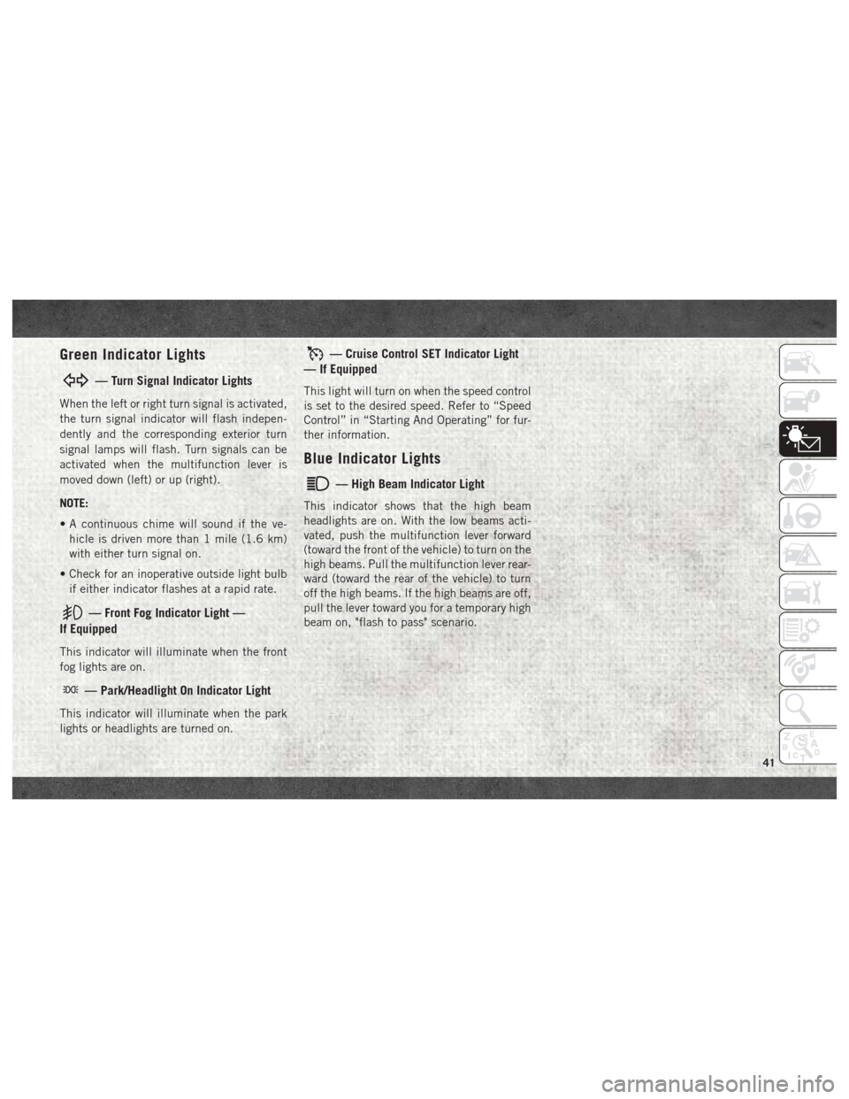
Green Indicator Lights
— Turn Signal Indicator Lights
When the left or right turn signal is activated,
the turn signal indicator will flash indepen-
dently and the corresponding exterior turn
signal lamps will flash. Turn signals can be
activated when the multifunction lever is
moved down (left) or up (right).
NOTE:
• A continuous chime will sound if the ve-hicle is driven more than 1 mile (1.6 km)
with either turn signal on.
• Check for an inoperative outside light bulb if either indicator flashes at a rapid rate.
— Front Fog Indicator Light —
If Equipped
This indicator will illuminate when the front
fog lights are on.
— Park/Headlight On Indicator Light
This indicator will illuminate when the park
lights or headlights are turned on.
— Cruise Control SET Indicator Light
— If Equipped
This light will turn on when the speed control
is set to the desired speed. Refer to “Speed
Control” in “Starting And Operating” for fur-
ther information.
Blue Indicator Lights
— High Beam Indicator Light
This indicator shows that the high beam
headlights are on. With the low beams acti-
vated, push the multifunction lever forward
(toward the front of the vehicle) to turn on the
high beams. Pull the multifunction lever rear-
ward (toward the rear of the vehicle) to turn
off the high beams. If the high beams are off,
pull the lever toward you for a temporary high
beam on, "flash to pass" scenario.
41
Page 64 of 204
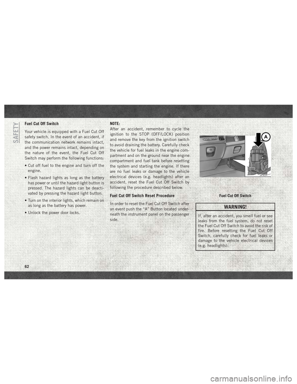
Fuel Cut Off Switch
Your vehicle is equipped with a Fuel Cut Off
safety switch. In the event of an accident, if
the communication network remains intact,
and the power remains intact, depending on
the nature of the event, the Fuel Cut Off
Switch may perform the following functions:
• Cut off fuel to the engine and turn off theengine.
• Flash hazard lights as long as the battery has power or until the hazard light button is
pressed. The hazard lights can be deacti-
vated by pressing the hazard light button.
• Turn on the interior lights, which remain on as long as the battery has power.
• Unlock the power door locks. NOTE:
After an accident, remember to cycle the
ignition to the STOP (OFF/LOCK) position
and remove the key from the ignition switch
to avoid draining the battery. Carefully check
the vehicle for fuel leaks in the engine com-
partment and on the ground near the engine
compartment and fuel tank before resetting
the system and starting the engine. If there
are no fuel leaks or damage to the vehicle
electrical devices (e.g. headlights) after an
accident, reset the Fuel Cut Off Switch by
following the procedure described below.
Fuel Cut Off Switch Reset Procedure
In order to reset the Fuel Cut Off Switch after
an event push the “A” Button located under-
neath the instrument panel on the passenger
side.WARNING!
If, after an accident, you smell fuel or see
leaks from the fuel system, do not reset
the Fuel Cut Off Switch to avoid the risk of
fire. Before resetting the Fuel Cut Off
Switch, carefully check for fuel leaks or
damage to the vehicle electrical devices
(e.g. headlights).
Fuel Cut Off Switch
SAFETY
62
Page 74 of 204
Periodic Safety Checks You
Should Make Outside The Vehicle
Tires
Examine tires for excessive tread wear and
uneven wear patterns. Check for stones,
nails, glass, or other objects lodged in the
tread or sidewall. Inspect the tread for cuts
and cracks. Inspect sidewalls for cuts,
cracks, and bulges. Check the wheel bolts for
tightness. Check the tires (including spare)
for proper cold inflation pressure.
Lights
Have someone observe the operation of brake
lights and exterior lights while you work the
controls. Check turn signal and high beam
indicator lights on the instrument panel.
Door Latches
Check for proper closing, latching, and lock-
ing.
Fluid Leaks
Check area under the vehicle after overnight
parking for fuel, coolant, oil, or other fluid
leaks. Also, if gasoline fumes are detected or
if fuel, or brake fluid leaks are suspected. The
cause should be located and corrected imme-
diately.
SAFETY
72
Page 77 of 204
CAUTION!
If the “Generic Warning Light” remains on
and a “Service Fuel Filter” message dis-
plays, DO NOT START engine before you
drain the water from the fuel filter housing
to avoid engine damage. Please see your
authorized dealer for draining the fuel
filter/water separator and fuel filter re-
placement.
Normal Starting Procedure
The gear selector must be in the NEUTRAL
(N) position, and the brake pedal must be
pressed, to allow engine cranking. Place the
gear selector in NEUTRAL (N) and apply the
brake pedal BEFORE turning the key to the
START/AVV position; otherwise, the engine
will not crank and the key must be cycled
OFF, then back on, before cranking is al-
lowed.
Observe the instrument panel cluster lights
when starting the engine.NOTE:
Normal starting of either a cold or a warm
engine is obtained without pumping or press-
ing the accelerator pedal.
1. Press and hold the brake pedal.
2. Place the gear selector into the NEUTRAL
(N) position while keeping the brake pedal
depressed.
3. Turn the ignition switch to the ON/RUN/ MAR position and watch the instrument
panel cluster lights.CAUTION!
If the “Generic Warning Light” remains on
and a “Service Fuel Filter” message dis-
plays, DO NOT START engine before you
drain the water from the fuel filter housing
to avoid engine damage. Please see your
authorized dealer for draining the fuel
filter/water separator and fuel filter re-
placement.
4. After the Glow Plug light turns off, turn the ignition switch to the AVV (START)
position to start the engine. Do not press
the accelerator during starting. 5. If you wish to stop the cranking of the
engine prior to the engine starting, release
the ignition key so that it turns back to the
ON/RUN position.
6. Check that the oil pressure warning light has turned off.
7. Release the parking brake.
To start the engine if the transmission is
faulty, the “Delayed startup” procedure may
be required.
NOTE:
Not all Transmission Failures requires the
“Delayed startup” Procedure, it depends on
the type of failure.(refer to "Instrument Clus-
ter Messages" under "Automated Manual
Transmission" in this section for further infor-
mation):
• Begin with the key in the OFF position.
• Press and hold the brake pedal.
• Turn the key to the START/AVV position and hold it there for at least seven seconds with
the brake depressed. The engine will start,
and the transmission will operate in recov-
ery mode (maximum gear permitted = 3rd,
75
Page 78 of 204
automatic mode not available). If the en-
gine does not start, contact your authorized
dealer.
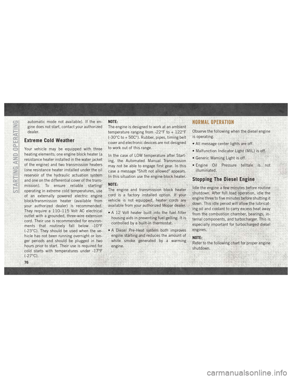
Extreme Cold Weather
Your vehicle may be equipped with three
heating elements; one engine block heater (a
resistance heater installed in the water jacket
of the engine) and two transmission heaters
(one resistance heater installed under the oil
reservoir of the hydraulic actuation system
and one on the differential cover of the trans-
mission). To ensure reliable starting/
operating in extreme cold temperatures, use
of an externally powered electric engine
block/transmission heater (available from
your authorized dealer) is recommended.
They require a 110–115 Volt AC electrical
outlet with a grounded, three-wire extension
cord. Their use is recommended for environ-
ments that routinely fall below -10°F
(-23°C). They should be used when the ve-
hicle has not been running overnight or lon-
ger periods and should be plugged in two
hours prior to start. Their use is required for
cold starts with temperatures under -17°F
(-27°C).NOTE:
The engine is designed to work at an ambient
temperature ranging from -22°F to + 122°F
(-30°C to + 50C°). Rubber, pipes, timing belt
cover and electronic devices are not designed
to work out of this range.
In the case of LOW temperature after Start-
ing, the Automated Manual Transmission
may not be able to engage first gear. In this
case a message "Shift not allowed" appears.
In this situation use the engine block heater.
NOTE:
The engine and transmission block heater
cord is a factory installed option. If your
vehicle is not equipped, heater cords are
available from your authorized Mopar dealer.
• A 12 Volt heater built into the fuel filter
housing aids in preventing fuel gelling. It is
controlled by a built-in thermostat.
• A Diesel Pre-Heat system both improves engine starting and reduces the amount of
white smoke generated by a warming
engine.
NORMAL OPERATION
Observe the following when the diesel engine
is operating.
• All message center lights are off.
• Malfunction Indicator Light (MIL) is off.
• Generic Warning Light is off.
• Engine Oil Pressure telltale is notilluminated.
Stopping The Diesel Engine
Idle the engine a few minutes before routine
shutdown. After full load operation, idle the
engine three to five minutes before shutting it
down. This idle period will allow the lubricat-
ing oil and coolant to carry excess heat away
from the combustion chamber, bearings, in-
ternal components, and turbocharger. This is
especially important for turbocharged diesel
engines.
NOTE:
Refer to the following chart for proper engine
shutdown.STARTING AND OPERATING
76
Page 108 of 204
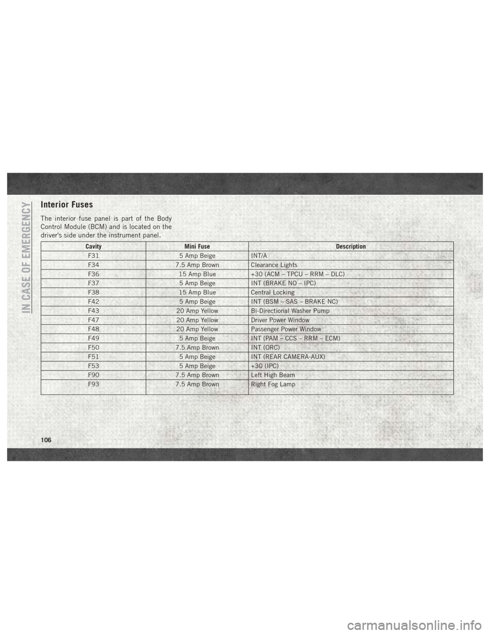
Interior Fuses
The interior fuse panel is part of the Body
Control Module (BCM) and is located on the
driver's side under the instrument panel.
CavityMini Fuse Description
F31 5 Amp BeigeINT/A
F34 7.5 Amp Brown Clearance Lights
F36 15 Amp Blue+30 (ACM – TPCU – RRM – DLC)
F37 5 Amp BeigeINT (BRAKE NO – IPC)
F38 15 Amp BlueCentral Locking
F42 5 Amp BeigeINT (BSM – SAS – BRAKE NC)
F43 20 Amp YellowBi-Directional Washer Pump
F47 20 Amp YellowDriver Power Window
F48 20 Amp YellowPassenger Power Window
F49 5 Amp BeigeINT (PAM – CCS – RRM – ECM)
F50 7.5 Amp Brown INT (ORC)
F51 5 Amp BeigeINT (REAR CAMERA-AUX)
F53 5 Amp Beige+30 (IPC)
F90 7.5 Amp Brown Left High Beam
F93 7.5 Amp Brown Right Fog Lamp
IN CASE OF EMERGENCY
106
Page 126 of 204
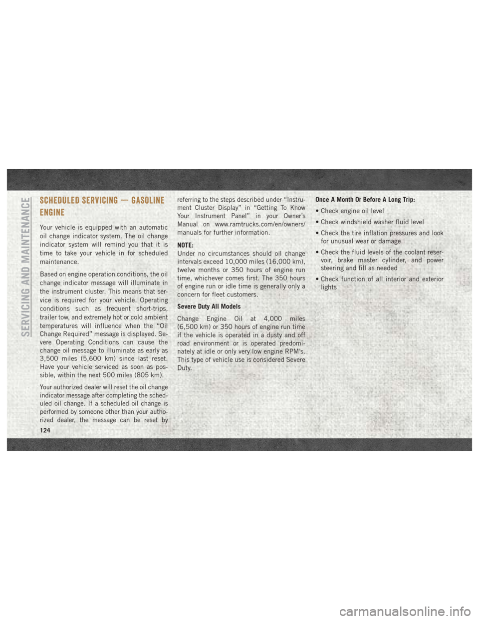
SCHEDULED SERVICING — GASOLINE
ENGINE
Your vehicle is equipped with an automatic
oil change indicator system. The oil change
indicator system will remind you that it is
time to take your vehicle in for scheduled
maintenance.
Based on engine operation conditions, the oil
change indicator message will illuminate in
the instrument cluster. This means that ser-
vice is required for your vehicle. Operating
conditions such as frequent short-trips,
trailer tow, and extremely hot or cold ambient
temperatures will influence when the “Oil
Change Required” message is displayed. Se-
vere Operating Conditions can cause the
change oil message to illuminate as early as
3,500 miles (5,600 km) since last reset.
Have your vehicle serviced as soon as pos-
sible, within the next 500 miles (805 km).
Your authorized dealer will reset the oil change
indicator message after completing the sched-
uled oil change. If a scheduled oil change is
performed by someone other than your autho-
rized dealer, the message can be reset byreferring to the steps described under “Instru-
ment Cluster Display” in “Getting To Know
Your Instrument Panel” in your Owner’s
Manual on
www.ramtrucks.com/en/owners/
manuals for further information.
NOTE:
Under no circumstances should oil change
intervals exceed 10,000 miles (16,000 km),
twelve months or 350 hours of engine run
time, whichever comes first. The 350 hours
of engine run or idle time is generally only a
concern for fleet customers.
Severe Duty All Models
Change Engine Oil at 4,000 miles
(6,500 km) or 350 hours of engine run time
if the vehicle is operated in a dusty and off
road environment or is operated predomi-
nately at idle or only very low engine RPM’s.
This type of vehicle use is considered Severe
Duty. Once A Month Or Before A Long Trip:
• Check engine oil level
• Check windshield washer fluid level
• Check the tire inflation pressures and look
for unusual wear or damage
• Check the fluid levels of the coolant reser- voir, brake master cylinder, and power
steering and fill as needed
• Check function of all interior and exterior lights
SERVICING AND MAINTENANCE
124
Page 130 of 204
Heavy Duty Use Of The Vehicle
Change engine oil at 4,000 miles (6,500 km)
or 350 hours of engine run time if the vehicle
is operated in a dusty and off road environ-
ment or is operated predominately at idle or
only very low engine RPM’s. This type of
vehicle use is considered Severe Duty.
SCHEDULED MAINTENANCE — DIESEL
ENGINE
Your vehicle is equipped with an automatic
oil change indicator system. The oil change
indicator system will remind you that it is
time to take your vehicle in for scheduled
maintenance.
Based on engine operation conditions, the oil
change indicator message will illuminate in
the instrument cluster. This means that ser-
vice is required for your vehicle. Operating
conditions such as frequent short-trips,
trailer tow, and extremely hot or cold ambient
temperatures will influence when the “Oil
Change Required” message is displayed. Se-
vere Operating Conditions can cause the
change oil message to illuminate as early as3,500 miles (5,600 km) since last reset.
Have your vehicle serviced as soon as pos-
sible, within the next 500 miles (805 km).
NOTE:
Under no circumstances should oil change
intervals exceed 18,500 miles (29,773 km)
or twelve months, whichever comes first.
Once A Month Or Before A Long Trip:
• Check engine oil level
• Check windshield washer fluid level
• Check the tire inflation pressures and look
for unusual wear or damage
• Check the fluid levels of the coolant reser- voir, brake master cylinder, and power
steering, and fill as needed
• Check function of all interior and exterior lights
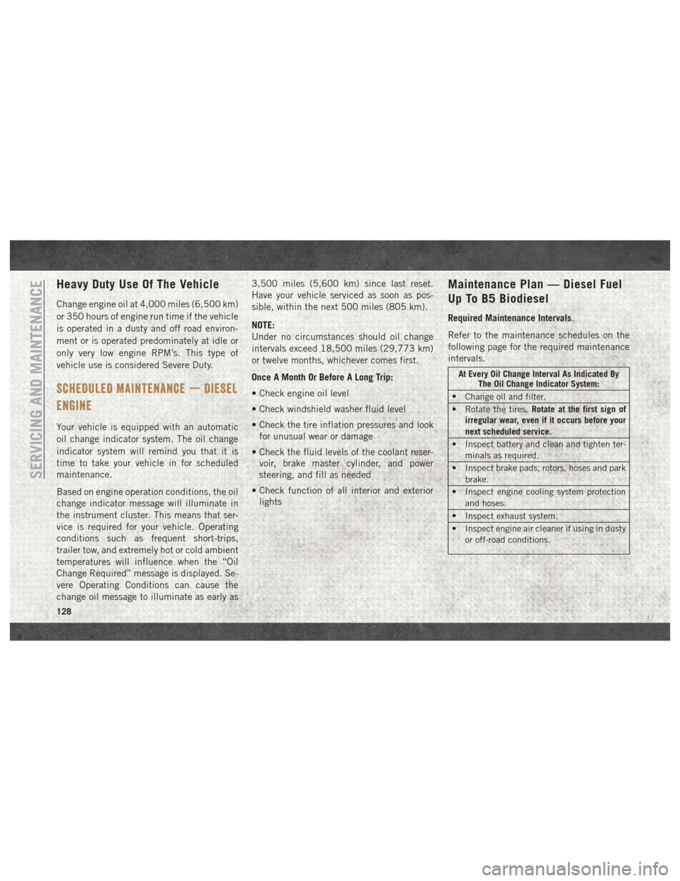
Maintenance Plan — Diesel Fuel
Up To B5 Biodiesel
Required Maintenance Intervals.
Refer to the maintenance schedules on the
following page for the required maintenance
intervals.
At Every Oil Change Interval As Indicated By The Oil Change Indicator System:
• Change oil and filter.
• Rotate the tires. Rotate at the first sign of
irregular wear, even if it occurs before your
next scheduled service.
• Inspect battery and clean and tighten ter- minals as required.
• Inspect brake pads, rotors, hoses and park brake.
• Inspect engine cooling system protection and hoses.
• Inspect exhaust system.
• Inspect engine air cleaner if using in dusty or off-road conditions.
SERVICING AND MAINTENANCE
128
Page 162 of 204
MOPAR ACCESSORIES
Authentic Accessories By Mopar
In choosing Authentic Accessories you gain
far more than expressive style, premium pro-
tection, or extreme entertainment, you also
benefit from enhancing your vehicle with
accessories that have been thoroughly tested
and factory-approved.
The following highlights just some of the
many Authentic Ram Accessories by Mopar
featuring a fit, finish, and functionality spe-
cifically for your Ram Promaster:EXTERIOR:
• Splash Guards
• Hitch Receiver
• Side Window Air Deflectors
• 7/4 Way Trailer Tow Wiring Harness
INTERIOR:
• B-Pillar Grab Handle
• D-Pillar Grab Handle
• All-Weather Floor Mats
• Premium Carpet Floor Mats
• Cargo Compartment Floor Liner
• DOT Certified Emergency Roadside Kit ELECTRONICS:
• Fog Lights
• Remote Start
• Back Up Camera
• Hands Free Bluetooth
• Mopar Connect (WiFi)
• Cargo Compartment LED Lighting
• Electronic Vehicle Tracking System
For the full line of Authentic Ram Accesso-
ries by Mopar, visit your local dealership or
online at mopar.com for U.S. residents and
mopar.ca for Canadian residents.
NOTE:
All parts are subject to availability.
TECHNICAL SPECIFICATIONS
160
Page 171 of 204
UCONNECT SETTINGS
The Uconnect system allows you to access
Customer Programmable feature settings
such as Display, Clock & Date, Safety/
Assistance, Lights, Doors & Locks, Audio,
Phone/Bluetooth, SiriusXM Setup, Restore
Default Settings and Clear Personal Data
through buttons on the touchscreen.To change a setting:
1. Push the SETTINGSbutton located
on the right side of the display.
2. Select a programmable feature you would like to adjust.
3. Make your selection highlighting the button.
Depending on the vehicles options, the following feature settings are available:
• Language • Doors & Locks
• Display • Engine Off Options
• Units (If Equipped) • Audio
• Voice • Phone
• Clock • SiriusXM Setup
• Safety/Assistance • Radio Setup
• Lights • Restore Settings
• Brakes • Clear Personal Data
Refer to “Uconnect Settings” in “Multime-
dia” in your Owner’s Manual. For U.S. resi-
dents, visit: www.mopar.com/en-us/care/
owners-manual.html. For Canadian resi-
dents, visit: www.owners.mopar.ca.
169