instrument panel Ram ProMaster 2018 Owner's Manual
[x] Cancel search | Manufacturer: RAM, Model Year: 2018, Model line: ProMaster, Model: Ram ProMaster 2018Pages: 204, PDF Size: 4 MB
Page 63 of 204

The SABICs may help reduce the risk of
partial or complete ejection of vehicle occu-
pants through side windows in certain roll-
over or side impact events.
Air Bag System Components
NOTE:
The Occupant Restraint Controller (ORC)
monitors the internal circuits and intercon-
necting wiring associated with electrical Air
Bag System Components listed below:
• Occupant Restraint Controller (ORC)
• Air Bag Warning Light
• Steering Wheel and Column
• Instrument Panel
• Driver and Front Passenger Air Bags
• Seat Belt Buckle Switch
• Supplemental Side Air Bags
• Front and Side Impact Sensors
• Seat Belt Pretensioners
If A Deployment Occurs
The front air bags are designed to deflate
immediately after deployment.NOTE:
Front and/or side air bags will not deploy in all
collisions. This does not mean something is
wrong with the air bag system.
If you do have a collision which deploys the
air bags, any or all of the following may occur:
• The air bag material may sometimes cause
abrasions and/or skin reddening to the oc-
cupants as the air bags deploy and unfold.
The abrasions are similar to friction rope
burns or those you might get sliding along a
carpet or gymnasium floor. They are not
caused by contact with chemicals. They are
not permanent and normally heal quickly.
However, if you haven’t healed significantly
within a few days, or if you have any blis-
tering, see your doctor immediately.
• As the air bags deflate, you may see some smoke-like particles. The particles are a
normal by-product of the process that gen-
erates the non-toxic gas used for air bag
inflation. These airborne particles may irri-
tate the skin, eyes, nose, or throat. If you
have skin or eye irritation, rinse the area
with cool water. For nose or throat irritation,
move to fresh air. If the irritation continues, see your doctor. If these particles settle on
your clothing, follow the garment manufac-
turer’s instructions for cleaning.
Do not drive your vehicle after the air bags
have deployed. If you are involved in another
collision, the air bags will not be in place to
protect you.
WARNING!
Deployed air bags and seat belt preten-
sioners cannot protect you in another col-
lision. Have the air bags, seat belt preten-
sioners, and the seat belt retractor
assemblies replaced by an authorized
dealer immediately. Also, have the Occu-
pant Restraint Controller System serviced
as well.
NOTE:
• Air bag covers may not be obvious in the interior trim, but they will open during air
bag deployment.
• After any collision, the vehicle should be taken to an authorized dealer immediately.
61
Page 64 of 204
Fuel Cut Off Switch
Your vehicle is equipped with a Fuel Cut Off
safety switch. In the event of an accident, if
the communication network remains intact,
and the power remains intact, depending on
the nature of the event, the Fuel Cut Off
Switch may perform the following functions:
• Cut off fuel to the engine and turn off theengine.
• Flash hazard lights as long as the battery has power or until the hazard light button is
pressed. The hazard lights can be deacti-
vated by pressing the hazard light button.
• Turn on the interior lights, which remain on as long as the battery has power.
• Unlock the power door locks. NOTE:
After an accident, remember to cycle the
ignition to the STOP (OFF/LOCK) position
and remove the key from the ignition switch
to avoid draining the battery. Carefully check
the vehicle for fuel leaks in the engine com-
partment and on the ground near the engine
compartment and fuel tank before resetting
the system and starting the engine. If there
are no fuel leaks or damage to the vehicle
electrical devices (e.g. headlights) after an
accident, reset the Fuel Cut Off Switch by
following the procedure described below.
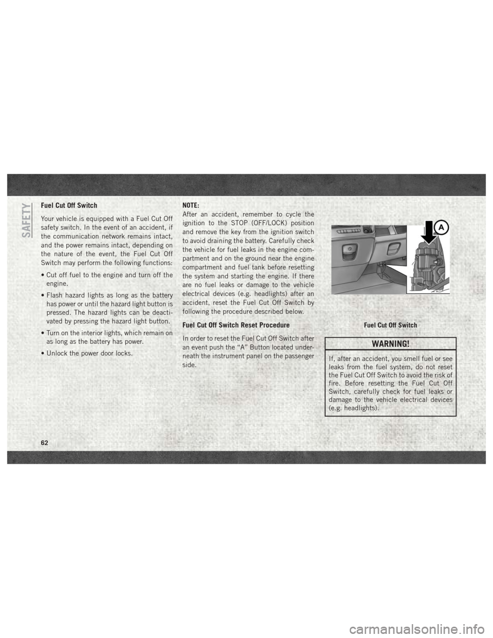
Fuel Cut Off Switch Reset Procedure
In order to reset the Fuel Cut Off Switch after
an event push the “A” Button located under-
neath the instrument panel on the passenger
side.WARNING!
If, after an accident, you smell fuel or see
leaks from the fuel system, do not reset
the Fuel Cut Off Switch to avoid the risk of
fire. Before resetting the Fuel Cut Off
Switch, carefully check for fuel leaks or
damage to the vehicle electrical devices
(e.g. headlights).
Fuel Cut Off Switch
SAFETY
62
Page 74 of 204
Periodic Safety Checks You
Should Make Outside The Vehicle
Tires
Examine tires for excessive tread wear and
uneven wear patterns. Check for stones,
nails, glass, or other objects lodged in the
tread or sidewall. Inspect the tread for cuts
and cracks. Inspect sidewalls for cuts,
cracks, and bulges. Check the wheel bolts for
tightness. Check the tires (including spare)
for proper cold inflation pressure.
Lights
Have someone observe the operation of brake
lights and exterior lights while you work the
controls. Check turn signal and high beam
indicator lights on the instrument panel.
Door Latches
Check for proper closing, latching, and lock-
ing.
Fluid Leaks
Check area under the vehicle after overnight
parking for fuel, coolant, oil, or other fluid
leaks. Also, if gasoline fumes are detected or
if fuel, or brake fluid leaks are suspected. The
cause should be located and corrected imme-
diately.
SAFETY
72
Page 77 of 204
CAUTION!
If the “Generic Warning Light” remains on
and a “Service Fuel Filter” message dis-
plays, DO NOT START engine before you
drain the water from the fuel filter housing
to avoid engine damage. Please see your
authorized dealer for draining the fuel
filter/water separator and fuel filter re-
placement.
Normal Starting Procedure
The gear selector must be in the NEUTRAL
(N) position, and the brake pedal must be
pressed, to allow engine cranking. Place the
gear selector in NEUTRAL (N) and apply the
brake pedal BEFORE turning the key to the
START/AVV position; otherwise, the engine
will not crank and the key must be cycled
OFF, then back on, before cranking is al-
lowed.
Observe the instrument panel cluster lights
when starting the engine.NOTE:
Normal starting of either a cold or a warm
engine is obtained without pumping or press-
ing the accelerator pedal.
1. Press and hold the brake pedal.
2. Place the gear selector into the NEUTRAL
(N) position while keeping the brake pedal
depressed.
3. Turn the ignition switch to the ON/RUN/ MAR position and watch the instrument
panel cluster lights.CAUTION!
If the “Generic Warning Light” remains on
and a “Service Fuel Filter” message dis-
plays, DO NOT START engine before you
drain the water from the fuel filter housing
to avoid engine damage. Please see your
authorized dealer for draining the fuel
filter/water separator and fuel filter re-
placement.
4. After the Glow Plug light turns off, turn the ignition switch to the AVV (START)
position to start the engine. Do not press
the accelerator during starting. 5. If you wish to stop the cranking of the
engine prior to the engine starting, release
the ignition key so that it turns back to the
ON/RUN position.
6. Check that the oil pressure warning light has turned off.
7. Release the parking brake.
To start the engine if the transmission is
faulty, the “Delayed startup” procedure may
be required.
NOTE:
Not all Transmission Failures requires the
“Delayed startup” Procedure, it depends on
the type of failure.(refer to "Instrument Clus-
ter Messages" under "Automated Manual
Transmission" in this section for further infor-
mation):
• Begin with the key in the OFF position.
• Press and hold the brake pedal.
• Turn the key to the START/AVV position and hold it there for at least seven seconds with
the brake depressed. The engine will start,
and the transmission will operate in recov-
ery mode (maximum gear permitted = 3rd,
75
Page 80 of 204

• Vary accelerator pedal position at highwayspeeds when carrying or towing significant
weight.
NOTE:
Light duty operation such as light trailer
towing or no load operation will extend the
time before the engine is at full efficiency.
Reduced fuel economy and power may be
seen at this time.
The engine oil installed in the engine at the
factory is a high-quality energy conserving
type lubricant. Oil changes should be consis-
tent with anticipated climate conditions un-
der which vehicle operations will occur. The
recommended viscosity and quality grades
are shown under “Fluids And Lubricants” in
the “Technical Specifications” chapter in
this manual. NON-DETERGENT OR
STRAIGHT MINERAL OILS MUST NEVER
BE USED.ELECTRIC PARK BRAKE (EPB) —
DIESEL ONLY (IF EQUIPPED)
Your vehicle is equipped with an Electric
Park Brake System (EPB) that offers simple
operation, and some additional features that
make the park brake more convenient and
useful.
The park brake is primarily intended to pre-
vent the vehicle from rolling while parked.
Before leaving the vehicle, make sure that
the park brake is applied.
You can engage the park brake in two ways;
• Manually, by applying the park brake switch.
• Automatically, by the Auto Park Brake fea- ture whenever the vehicle speed is below
1.25 mph (2 km/h) and the ignition switch
is in the STOP/OFF position.
The park brake switch is located on the in-
strument panel to the right of the instrument
cluster. To apply the parking brake manually, pull and
tilt the top of the switch away from the
instrument panel momentarily. You may hear
a mechanical sound while the parking brake
operates; this is normal operating noise.
Once the parking brake is fully engaged, the
BRAKE warning lamp in the instrument clus-
ter and an indicator on the switch will illumi-
nate. The park brake can be applied even
Electric Park Brake SwitchSTARTING AND OPERATING
78
Page 93 of 204
WARNING!
ditions, and you could lose control and
have an accident. Do not use Speed Con-
trol in heavy traffic or on roads that are
winding, icy, snow-covered or slippery.
To Resume Speed
To resume a previously set speed, push the
RES button and release. Resume can be used
at any speed above 20 mph (32 km/h) up to
the maximum speed of 100 mph (160 km/h).
To Deactivate
A soft tap on the brake pedal, pushing the
RES button, or normal brake pressure while
slowing the vehicle will deactivate Speed
Control without erasing the set speed
memory. Rotating the center ring upward to
turn the system off or turning the ignition
switch OFF erases the set speed memory.
PARKSENSE REAR PARK ASSIST
If an obstacle is behind the vehicle when
REVERSE gear is engaged, an audible alert is
activated.The tones emitted by the loudspeaker inform
the driver that the vehicle is approaching an
obstacle. The pauses between the tones are
directly proportional to the distance from the
obstacle. Pulses emitted in quick succession
indicate the presence of a very close ob-
stacle. A continuous tone indicates that the
obstacle is less than 12 inches (30 cm) away.
PARKVIEW REAR BACK-UP CAMERA
You can see an on-screen image of the rear of
your vehicle whenever the gear selector is put
into REVERSE. The ParkView Rear Back-Up
Camera image is displayed on the touch-
screen display located on the center stack of
the instrument panel.
NOTE:
If the touchscreen display appears foggy,
clean the camera lens located on the top rear
of the vehicle below the center light.
WARNING!
Drivers must be careful when backing up
even when using the Rear Back-Up Cam-
era. Always check carefully behind your
WARNING!
vehicle, and be sure to check for pedestri-
ans, animals, other vehicles, obstructions,
or blind spots before backing up. You are
responsible for the safety of your surround-
ings and must continue to pay attention
while backing up. Failure to do so can
result in serious injury or death.
REFUELING THE VEHICLE — GAS
ENGINE
The gas cap is located behind the fuel filler
door on the left side of the vehicle. If the gas
cap is lost or damaged, be sure the replace-
ment cap is for use with this vehicle.
WARNING!
• Never have any smoking materials lit in
or near the vehicle when the fuel door is
open or the tank is being filled.
• Never add fuel when the engine is run-
ning. This is in violation of most state
and federal fire regulations and may
91
Page 96 of 204

The DEF injection system and SCR catalyst
enable the achievement of diesel emissions
requirements; while maintaining outstanding
fuel economy, drivability, torque and power
ratings.
Refer to “Instrument Cluster Display” in
“Getting To Know Your Instrument Panel” for
system messages and warnings.
NOTE:
• Your vehicle is equipped with a DEF injec-tion system. You may occasionally hear an
audible clicking noise from under the ve-
hicle at a stop. This is normal operation.
• The DEF pump will run for a period of time after engine shutdown to purge the DEF
system. This is normal operation and may
be audible from under the vehicle.
Adding Diesel Exhaust Fluid
NOTE:
Driving conditions (altitude, vehicle speed,
load, etc.) will effect the amount of DEF that
is used by your vehicle.
DEF Fill Procedure
NOTE:
Refer to “Fluids And Lubricants” in “Techni-
cal Specifications” for the correct fluid type.
CAUTION!
It is extremely important to avoid any con-
tamination of the diesel fuel with Diesel
Exhaust Fluid (DEF). Ensure that the die-
sel fuel filler cap is in place and com-
pletely tightened before opening or filling
the DEF.
1. Remove cap from DEF filler neck (located on drivers side of the vehicle in the fuel
door).
2. Insert DEF fill adapter/nozzle into DEF tank filler neck.
CAUTION!
•To avoid DEF spillage, and possible dam-
age to the DEF tank from overfilling, do
not “top off” the DEF tank after filling.
• DO NOT OVERFILL. DEF will freeze be- low 12ºF (-11ºC). The DEF system is
designed to work in temperatures below
the DEF freezing point, however, if the
tank is overfilled and freezes, the system
could be damaged.
Fuel/DEF Fill Locations
1 — Diesel Fuel Fill Location
2 — Diesel Exhaust Fluid (DEF) Fill
Location
STARTING AND OPERATING
94
Page 108 of 204
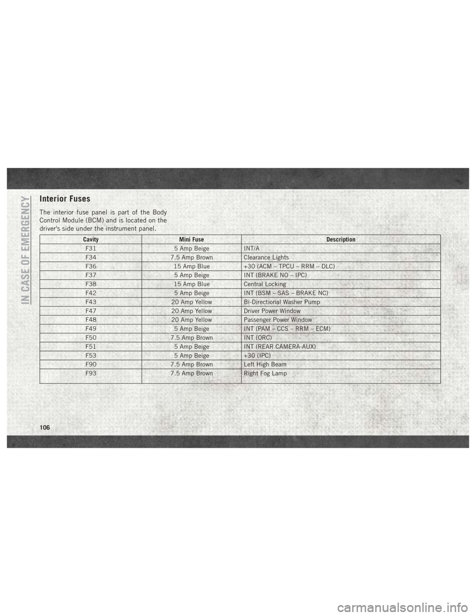
Interior Fuses
The interior fuse panel is part of the Body
Control Module (BCM) and is located on the
driver's side under the instrument panel.
CavityMini Fuse Description
F31 5 Amp BeigeINT/A
F34 7.5 Amp Brown Clearance Lights
F36 15 Amp Blue+30 (ACM – TPCU – RRM – DLC)
F37 5 Amp BeigeINT (BRAKE NO – IPC)
F38 15 Amp BlueCentral Locking
F42 5 Amp BeigeINT (BSM – SAS – BRAKE NC)
F43 20 Amp YellowBi-Directional Washer Pump
F47 20 Amp YellowDriver Power Window
F48 20 Amp YellowPassenger Power Window
F49 5 Amp BeigeINT (PAM – CCS – RRM – ECM)
F50 7.5 Amp Brown INT (ORC)
F51 5 Amp BeigeINT (REAR CAMERA-AUX)
F53 5 Amp Beige+30 (IPC)
F90 7.5 Amp Brown Left High Beam
F93 7.5 Amp Brown Right Fog Lamp
IN CASE OF EMERGENCY
106
Page 126 of 204
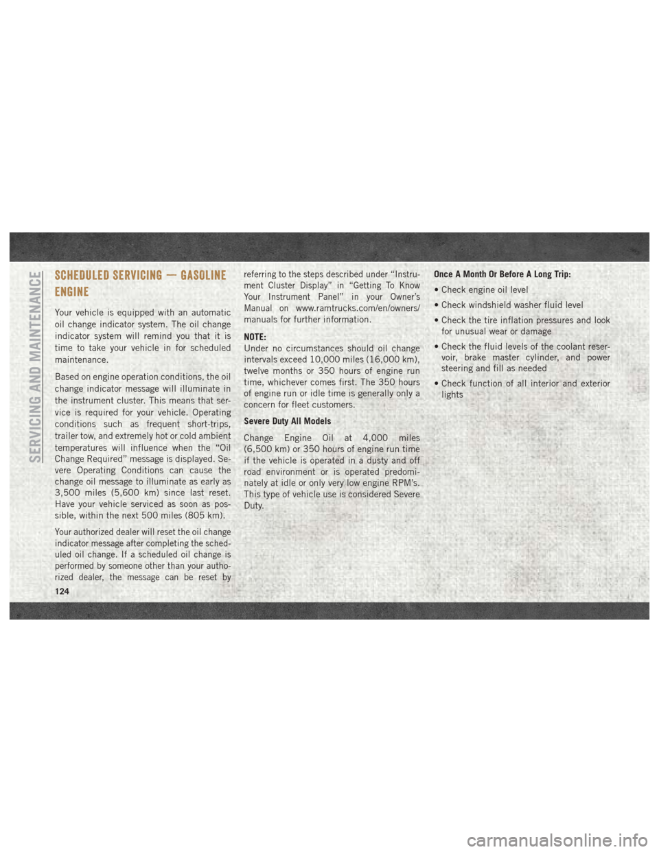
SCHEDULED SERVICING — GASOLINE
ENGINE
Your vehicle is equipped with an automatic
oil change indicator system. The oil change
indicator system will remind you that it is
time to take your vehicle in for scheduled
maintenance.
Based on engine operation conditions, the oil
change indicator message will illuminate in
the instrument cluster. This means that ser-
vice is required for your vehicle. Operating
conditions such as frequent short-trips,
trailer tow, and extremely hot or cold ambient
temperatures will influence when the “Oil
Change Required” message is displayed. Se-
vere Operating Conditions can cause the
change oil message to illuminate as early as
3,500 miles (5,600 km) since last reset.
Have your vehicle serviced as soon as pos-
sible, within the next 500 miles (805 km).
Your authorized dealer will reset the oil change
indicator message after completing the sched-
uled oil change. If a scheduled oil change is
performed by someone other than your autho-
rized dealer, the message can be reset byreferring to the steps described under “Instru-
ment Cluster Display” in “Getting To Know
Your Instrument Panel” in your Owner’s
Manual on
www.ramtrucks.com/en/owners/
manuals for further information.
NOTE:
Under no circumstances should oil change
intervals exceed 10,000 miles (16,000 km),
twelve months or 350 hours of engine run
time, whichever comes first. The 350 hours
of engine run or idle time is generally only a
concern for fleet customers.
Severe Duty All Models
Change Engine Oil at 4,000 miles
(6,500 km) or 350 hours of engine run time
if the vehicle is operated in a dusty and off
road environment or is operated predomi-
nately at idle or only very low engine RPM’s.
This type of vehicle use is considered Severe
Duty. Once A Month Or Before A Long Trip:
• Check engine oil level
• Check windshield washer fluid level
• Check the tire inflation pressures and look
for unusual wear or damage
• Check the fluid levels of the coolant reser- voir, brake master cylinder, and power
steering and fill as needed
• Check function of all interior and exterior lights
SERVICING AND MAINTENANCE
124
Page 164 of 204
CYBERSECURITY
Your vehicle may be a connected vehicle and
may be equipped with both wired and wire-
less networks. These networks allow your
vehicle to send and receive information. This
information allows systems and features in
your vehicle to function properly.
Your vehicle may be equipped with certain
security features to reduce the risk of unau-
thorized and unlawful access to vehicle sys-
tems and wireless communications. Vehicle
software technology continues to evolve over
time and FCA US LLC, working with its sup-
pliers, evaluates and takes appropriate steps
as needed. Similar to a computer or other
devices, your vehicle may require software
updates to improve the usability and perfor-
mance of your systems or to reduce the po-
tential risk of unauthorized and unlawful ac-
cess to your vehicle systems.
The risk of unauthorized and unlawful access
to your vehicle systems may still exist, even if
the most recent version of vehicle software
(such as Uconnect software) is installed.
WARNING!
• It is not possible to know or to predict allof the possible outcomes if your vehi-
cle’s systems are breached. It may be
possible that vehicle systems, including
safety related systems, could be im-
paired or a loss of vehicle control could
occur that may result in an accident
involving serious injury or death.
• ONLY insert media (e.g., USB, SD card,
or CD) into your vehicle if it came from a
trusted source. Media of unknown origin
could possibly contain malicious soft-
ware, and if installed in your vehicle, it
may increase the possibility for vehicle
systems to be breached.
• As always, if you experience unusual
vehicle behavior, take your vehicle to
your nearest authorized dealer immedi-
ately. NOTE:
• FCA or your dealer may contact you directly
regarding software updates.
• To help further improve vehicle security and minimize the potential risk of a secu-
rity breach, vehicle owners should: –
Routinely checkwww.driveuconnect.com/
software-update
to learn about available
Uconnect software updates.
– Only connect and use trusted media devices (e.g. personal mobile phones,
USBs, CDs).
Privacy of any wireless and wired communi-
cations cannot be assured. Third parties may
unlawfully intercept information and private
communications without your consent. For
further information, refer to “Onboard Diag-
nostic System (OBD II) Cybersecurity” in
“Getting To Know Your Instrument Panel” in
your Owner’s Manual at www.mopar.com/
en-us/care/owners-manual.html (U.S. Resi-
dents) or www.owners.mopar.ca (Canada
Residents) for further information.
MULTIMEDIA
162