warning light Ram ProMaster 2018 Owner's Manual
[x] Cancel search | Manufacturer: RAM, Model Year: 2018, Model line: ProMaster, Model: Ram ProMaster 2018Pages: 204, PDF Size: 4 MB
Page 64 of 204
Fuel Cut Off Switch
Your vehicle is equipped with a Fuel Cut Off
safety switch. In the event of an accident, if
the communication network remains intact,
and the power remains intact, depending on
the nature of the event, the Fuel Cut Off
Switch may perform the following functions:
• Cut off fuel to the engine and turn off theengine.
• Flash hazard lights as long as the battery has power or until the hazard light button is
pressed. The hazard lights can be deacti-
vated by pressing the hazard light button.
• Turn on the interior lights, which remain on as long as the battery has power.
• Unlock the power door locks. NOTE:
After an accident, remember to cycle the
ignition to the STOP (OFF/LOCK) position
and remove the key from the ignition switch
to avoid draining the battery. Carefully check
the vehicle for fuel leaks in the engine com-
partment and on the ground near the engine
compartment and fuel tank before resetting
the system and starting the engine. If there
are no fuel leaks or damage to the vehicle
electrical devices (e.g. headlights) after an
accident, reset the Fuel Cut Off Switch by
following the procedure described below.
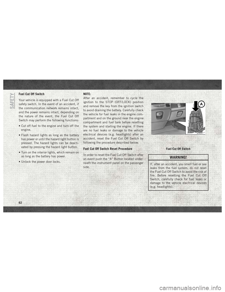
Fuel Cut Off Switch Reset Procedure
In order to reset the Fuel Cut Off Switch after
an event push the “A” Button located under-
neath the instrument panel on the passenger
side.WARNING!
If, after an accident, you smell fuel or see
leaks from the fuel system, do not reset
the Fuel Cut Off Switch to avoid the risk of
fire. Before resetting the Fuel Cut Off
Switch, carefully check for fuel leaks or
damage to the vehicle electrical devices
(e.g. headlights).
Fuel Cut Off Switch
SAFETY
62
Page 72 of 204

WARNING!
• If you are required to drive with thetrunk/liftgate/rear doors open, make sure
that all windows are closed and the cli-
mate control BLOWER switch is set at
high speed. DO NOT use the recircula-
tion mode.
• If it is necessary to sit in a parked vehicle
with the engine running, adjust your
heating or cooling controls to force out-
side air into the vehicle. Set the blower
at high speed.
The best protection against carbon monoxide
entry into the vehicle body is a properly
maintained engine exhaust system.
Whenever a change is noticed in the sound of
the exhaust system, when exhaust fumes can
be detected inside the vehicle, or when the
underside or rear of the vehicle is damaged,
have a competent mechanic inspect the com-
plete exhaust system and adjacent body ar-
eas for broken, damaged, deteriorated, or
mispositioned parts. Open seams or loose
connections could permit exhaust fumes to
seep into the passenger compartment. In addition, inspect the exhaust system each
time the vehicle is raised for lubrication or oil
change. Replace as required.
Safety Checks You Should Make
Inside The Vehicle
Seat Belts
Inspect the seat belt system periodically,
checking for cuts, frays, and loose parts.
Damaged parts must be replaced immedi-
ately. Do not disassemble or modify the sys-
tem.
Front seat belt assemblies must be replaced
after a collision. Rear seat belt assemblies
must be replaced after a collision if they have
been damaged (i.e., bent retractor, torn web-
bing, etc.). If there is any question regarding
seat belt or retractor condition, replace the
seat belt.
Air Bag Warning Light
The Air Bag warning lightwill turn on for
four to eight seconds as a bulb check when
the ignition switch is first turned to ON/RUN.
If the light is either not on during starting, stays on, or turns on while driving, have the
system inspected at your authorized dealer as
soon as possible. After the bulb check, this
light will illuminate with a single chime when
a fault with the Air Bag System has been
detected. It will stay on until the fault is
cleared. If the light comes on intermittently
or remains on while driving, have your autho-
rized dealer service the vehicle immediately.
Refer to “Occupant Restraint Systems” in
“Safety” for further information.
Defroster
Check operation by selecting the defrost
mode and place the blower control on high
speed. You should be able to feel the air
directed against the windshield. See your
authorized dealer for service if your defroster
is inoperable.
Floor Mat Safety Information
Always use floor mats designed to fit your
vehicle. Only use a floor mat that does not
interfere with the operation of the accelera-
tor, brake or clutch pedals. Only use a floor
mat that is securely attached using the floor
SAFETY
70
Page 73 of 204

mat fasteners so it cannot slip out of position
and interfere with the accelerator, brake or
clutch pedals or impair safe operation of your
vehicle in other ways.
WARNING!
An improperly attached, damaged, folded,
or stacked floor mat, or damaged floor mat
fasteners may cause your floor mat to in-
terfere with the accelerator, brake, or
clutch pedals and cause a loss of vehicle
control. To prevent SERIOUS INJURY or
DEATH:
• ALWAYS securely attach
your floor
mat using the floor mat fasteners. DO
NOT install your floor mat upside down
or turn your floor mat over. Lightly pull to
confirm mat is secured using the floor
mat fasteners on a regular basis.
• ALWAYS REMOVE THE EXISTING
FLOOR MAT FROM THE VEHICLE
before installing any other floor mat.
NEVER install or stack an additional
floor mat on top of an existing floor mat.
• ONLY install floor mats designed to fit
your vehicle. NEVER install a floor mat
WARNING!
that cannot be properly attached and
secured to your vehicle. If a floor mat
needs to be replaced, only use a FCA
approved floor mat for the specific
make, model, and year of your vehicle.
• ONLY use the driver’s side floor mat on
the driver’s side floor area. To check for
interference, with the vehicle properly
parked with the engine off, fully depress
the accelerator, the brake, and the
clutch pedal (if present) to check for
interference. If your floor mat interferes
with the operation of any pedal, or is not
secure to the floor, remove the floor mat
from the vehicle and place the floor mat
in your trunk.
• ONLY use the passenger’s side floor mat
on the passenger’s side floor area.
• ALWAYS make sure objects cannot fall or
slide into the driver’s side floor area
when the vehicle is moving. Objects can
become trapped under accelerator,
brake, or clutch pedals and could cause
a loss of vehicle control.
WARNING!
• NEVER place any objects under the floormat (e.g., towels, keys, etc.). These ob-
jects could change the position of the
floor mat and may cause interference
with the accelerator, brake, or clutch
pedals.
• If the vehicle carpet has been removed
and re-installed, always properly attach
carpet to the floor and check the floor
mat fasteners are secure to the vehicle
carpet. Fully depress each pedal to
check for interference with the accelera-
tor, brake, or clutch pedals then re-
install the floor mats.
• It is recommended to only use mild soap
and water to clean your floor mats. After
cleaning, always check your floor mat
has been properly installed and is se-
cured to your vehicle using the floor mat
fasteners by lightly pulling mat.
71
Page 77 of 204
CAUTION!
If the “Generic Warning Light” remains on
and a “Service Fuel Filter” message dis-
plays, DO NOT START engine before you
drain the water from the fuel filter housing
to avoid engine damage. Please see your
authorized dealer for draining the fuel
filter/water separator and fuel filter re-
placement.
Normal Starting Procedure
The gear selector must be in the NEUTRAL
(N) position, and the brake pedal must be
pressed, to allow engine cranking. Place the
gear selector in NEUTRAL (N) and apply the
brake pedal BEFORE turning the key to the
START/AVV position; otherwise, the engine
will not crank and the key must be cycled
OFF, then back on, before cranking is al-
lowed.
Observe the instrument panel cluster lights
when starting the engine.NOTE:
Normal starting of either a cold or a warm
engine is obtained without pumping or press-
ing the accelerator pedal.
1. Press and hold the brake pedal.
2. Place the gear selector into the NEUTRAL
(N) position while keeping the brake pedal
depressed.
3. Turn the ignition switch to the ON/RUN/ MAR position and watch the instrument
panel cluster lights.CAUTION!
If the “Generic Warning Light” remains on
and a “Service Fuel Filter” message dis-
plays, DO NOT START engine before you
drain the water from the fuel filter housing
to avoid engine damage. Please see your
authorized dealer for draining the fuel
filter/water separator and fuel filter re-
placement.
4. After the Glow Plug light turns off, turn the ignition switch to the AVV (START)
position to start the engine. Do not press
the accelerator during starting. 5. If you wish to stop the cranking of the
engine prior to the engine starting, release
the ignition key so that it turns back to the
ON/RUN position.
6. Check that the oil pressure warning light has turned off.
7. Release the parking brake.
To start the engine if the transmission is
faulty, the “Delayed startup” procedure may
be required.
NOTE:
Not all Transmission Failures requires the
“Delayed startup” Procedure, it depends on
the type of failure.(refer to "Instrument Clus-
ter Messages" under "Automated Manual
Transmission" in this section for further infor-
mation):
• Begin with the key in the OFF position.
• Press and hold the brake pedal.
• Turn the key to the START/AVV position and hold it there for at least seven seconds with
the brake depressed. The engine will start,
and the transmission will operate in recov-
ery mode (maximum gear permitted = 3rd,
75
Page 78 of 204
automatic mode not available). If the en-
gine does not start, contact your authorized
dealer.
Extreme Cold Weather
Your vehicle may be equipped with three
heating elements; one engine block heater (a
resistance heater installed in the water jacket
of the engine) and two transmission heaters
(one resistance heater installed under the oil
reservoir of the hydraulic actuation system
and one on the differential cover of the trans-
mission). To ensure reliable starting/
operating in extreme cold temperatures, use
of an externally powered electric engine
block/transmission heater (available from
your authorized dealer) is recommended.
They require a 110–115 Volt AC electrical
outlet with a grounded, three-wire extension
cord. Their use is recommended for environ-
ments that routinely fall below -10°F
(-23°C). They should be used when the ve-
hicle has not been running overnight or lon-
ger periods and should be plugged in two
hours prior to start. Their use is required for
cold starts with temperatures under -17°F
(-27°C).NOTE:
The engine is designed to work at an ambient
temperature ranging from -22°F to + 122°F
(-30°C to + 50C°). Rubber, pipes, timing belt
cover and electronic devices are not designed
to work out of this range.
In the case of LOW temperature after Start-
ing, the Automated Manual Transmission
may not be able to engage first gear. In this
case a message "Shift not allowed" appears.
In this situation use the engine block heater.
NOTE:
The engine and transmission block heater
cord is a factory installed option. If your
vehicle is not equipped, heater cords are
available from your authorized Mopar dealer.
• A 12 Volt heater built into the fuel filter
housing aids in preventing fuel gelling. It is
controlled by a built-in thermostat.
• A Diesel Pre-Heat system both improves engine starting and reduces the amount of
white smoke generated by a warming
engine.
NORMAL OPERATION
Observe the following when the diesel engine
is operating.
• All message center lights are off.
• Malfunction Indicator Light (MIL) is off.
• Generic Warning Light is off.
• Engine Oil Pressure telltale is notilluminated.
Stopping The Diesel Engine
Idle the engine a few minutes before routine
shutdown. After full load operation, idle the
engine three to five minutes before shutting it
down. This idle period will allow the lubricat-
ing oil and coolant to carry excess heat away
from the combustion chamber, bearings, in-
ternal components, and turbocharger. This is
especially important for turbocharged diesel
engines.
NOTE:
Refer to the following chart for proper engine
shutdown.STARTING AND OPERATING
76
Page 80 of 204

• Vary accelerator pedal position at highwayspeeds when carrying or towing significant
weight.
NOTE:
Light duty operation such as light trailer
towing or no load operation will extend the
time before the engine is at full efficiency.
Reduced fuel economy and power may be
seen at this time.
The engine oil installed in the engine at the
factory is a high-quality energy conserving
type lubricant. Oil changes should be consis-
tent with anticipated climate conditions un-
der which vehicle operations will occur. The
recommended viscosity and quality grades
are shown under “Fluids And Lubricants” in
the “Technical Specifications” chapter in
this manual. NON-DETERGENT OR
STRAIGHT MINERAL OILS MUST NEVER
BE USED.ELECTRIC PARK BRAKE (EPB) —
DIESEL ONLY (IF EQUIPPED)
Your vehicle is equipped with an Electric
Park Brake System (EPB) that offers simple
operation, and some additional features that
make the park brake more convenient and
useful.
The park brake is primarily intended to pre-
vent the vehicle from rolling while parked.
Before leaving the vehicle, make sure that
the park brake is applied.
You can engage the park brake in two ways;
• Manually, by applying the park brake switch.
• Automatically, by the Auto Park Brake fea- ture whenever the vehicle speed is below
1.25 mph (2 km/h) and the ignition switch
is in the STOP/OFF position.
The park brake switch is located on the in-
strument panel to the right of the instrument
cluster. To apply the parking brake manually, pull and
tilt the top of the switch away from the
instrument panel momentarily. You may hear
a mechanical sound while the parking brake
operates; this is normal operating noise.
Once the parking brake is fully engaged, the
BRAKE warning lamp in the instrument clus-
ter and an indicator on the switch will illumi-
nate. The park brake can be applied even
Electric Park Brake SwitchSTARTING AND OPERATING
78
Page 81 of 204

when the ignition switch is OFF however, it
can only be released when the ignition switch
is in the ON/RUN position.
NOTE:
The EPB fault lamp will illuminate if the EPB
switch is held for longer than 20 seconds if
vehicle speed is less than 1.25 mph (2 kph),
or 60 seconds if vehicle speed is greater than
1.25 mph (2 kph), in either the released or
applied position. The light will extinguish
upon releasing the switch.
The park brake will automatically engage
whenever the ignition switch is turned OFF
and the vehicle speed is below 1.25 mph
(2 km/h) via the Auto Park Brake feature.
The electric park brake will automatically
release if the engine is on and all following
conditions are met:
1. Driver's weight is detected on the driver'sseat.
2. Driver's seat is locked in forward direction (if equipped with swivel seat).
3. Transmission is in forward or reverse gears. 4. The accelerator pedal is pressed.
Or
1. Driver’s weight is detected on the driver’s
seat.
2. Driver’s seat is locked in forward direction (if equipped with swivel seat).
3. Transmission is moved from NEUTRAL to DRIVE or REVERSE gears.
4. Brake pedal is pressed.
5. Vehicle is on a slope less than 5 percent.
To release the park brake manually, the igni-
tion switch must be in the ON/RUN position.
Put your foot on the brake pedal, then push
the parking brake switch down momentarily.
Once the park brake is fully disengaged, the
BRAKE warning lamp in the instrument clus-
ter and the LED indicator on the switch will
extinguish.
If during drive away the driver pulls the EPB
switch (apply position) the drive away is
halted and EPB will be reapplied.WARNING!
To prevent SERIOUS INJURY or DEATH:
• NEVER install a driver seat cover or any other accessory on your driver seat.
• NEVER make any modifications to the
driver seat components, assembly, or
factory installed seat cover.
• NEVER place objects under the driver
seat.
If your driver seat needs service for any
reason, take your vehicle to your autho-
rized dealer immediately.
NOTE:
• When parking on a hill, it is important to turn the front wheels toward the curb on a
downhill grade and away from the curb on
an uphill grade. The parking brake should
always be applied whenever the driver is not
in the vehicle.
• The Electronic Park Brake system commu- nicates with the Driver Presence Detection
sensor installed in the driver seat. The use
of seat covers or seat accessories could
79
Page 82 of 204
prevent the Electronic Park Brake system
from working properly and result in unin-
tended vehicle movement.
WARNING!
• When leaving the vehicle, always removethe key fob from the ignition and lock
your vehicle.
• Never leave children alone in a vehicle,
or with access to an unlocked vehicle.
Allowing children to be in a vehicle un-
attended is dangerous for a number of
reasons. A child or others could be seri-
ously or fatally injured. Children should
be warned not to touch the parking
brake, brake pedal or the gear selector.
• Do not leave the key fob in or near the
vehicle, or in a location accessible to
children, and do not leave a vehicle
equipped with Keyless Enter-N-Go in
the ACC or ON/RUN mode. A child could
operate power windows, other controls,
or move the vehicle.
• Be sure the parking brake is fully disen-
gaged before driving; failure to do so can
lead to brake failure and a collision.
WARNING!
• Always fully apply the parking brakewhen leaving your vehicle, or it may roll
and cause damage or injury.
CAUTION!
If the Brake System Warning Light remains
on with the parking brake released, a brake
system malfunction is indicated. Have the
brake system serviced by an authorized
dealer immediately.
If exceptional circumstances should make it
necessary to engage the park brake while the
vehicle is in motion, a buzzer repeats until
the park brake switch is released or vehicle
speed is below 1.25 mph (2 km/h).
To disengage the park brake while the vehicle
is in motion, release the switch. If the vehicle
is brought to a complete stop using the park
brake, when the vehicle reaches approxi-
mately 1.25 mph (2 km/h) the parking brake
will remain engaged.
WARNING!
Driving the vehicle with the parking brake
engaged, or repeated use of the parking
brake to slow the vehicle may cause seri-
ous damage to the brake system. Be sure
the parking brake is fully disengaged be-
fore driving; failure to do so can lead to
brake failure and a collision.
In the unlikely event of a malfunction of the
Electric Park Brake system, a yellow triangle
EPB fault lamp will illuminate. In this status
some EPB functionality may be deactivated,
in this event, urgent service of the electric
park brake system is required. Do not rely on
the parking brake to hold the vehicle station-
ary, wheel chocks or other mechanical secur-
ing of the vehicle is required to prevent roll-
ing.
Loss Of Electric Power
If electric power is not available and the EPB
must be released for towing the vehicle, the
EPB can be mechanically released by use of
STARTING AND OPERATING
80
Page 91 of 204
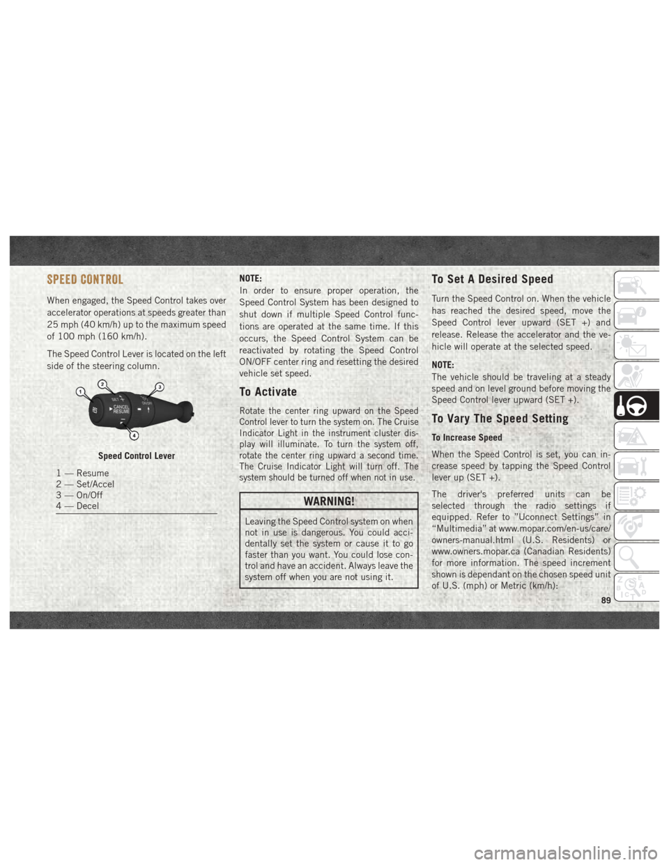
SPEED CONTROL
When engaged, the Speed Control takes over
accelerator operations at speeds greater than
25 mph (40 km/h) up to the maximum speed
of 100 mph (160 km/h).
The Speed Control Lever is located on the left
side of the steering column.NOTE:
In order to ensure proper operation, the
Speed Control System has been designed to
shut down if multiple Speed Control func-
tions are operated at the same time. If this
occurs, the Speed Control System can be
reactivated by rotating the Speed Control
ON/OFF center ring and resetting the desired
vehicle set speed.
To Activate
Rotate the center ring upward on the Speed
Control lever to turn the system on. The Cruise
Indicator Light in the instrument cluster dis-
play will illuminate. To turn the system off,
rotate the center ring upward a second time.
The Cruise Indicator Light will turn off. The
system should be turned off when not in use.
WARNING!
Leaving the Speed Control system on when
not in use is dangerous. You could acci-
dentally set the system or cause it to go
faster than you want. You could lose con-
trol and have an accident. Always leave the
system off when you are not using it.
To Set A Desired Speed
Turn the Speed Control on. When the vehicle
has reached the desired speed, move the
Speed Control lever upward (SET +) and
release. Release the accelerator and the ve-
hicle will operate at the selected speed.
NOTE:
The vehicle should be traveling at a steady
speed and on level ground before moving the
Speed Control lever upward (SET +).
To Vary The Speed Setting
To Increase Speed
When the Speed Control is set, you can in-
crease speed by tapping the Speed Control
lever up (SET +).
The driver's preferred units can be
selected through the radio settings if
equipped. Refer to ”Uconnect Settings” in
“Multimedia” at www.mopar.com/en-us/care/
owners-manual.html (U.S. Residents) or
www.owners.mopar.ca (Canadian Residents)
for more information. The speed increment
shown is dependant on the chosen speed unit
of U.S. (mph) or Metric (km/h):
Speed Control Lever
1 — Resume
2 — Set/Accel
3 — On/Off
4 — Decel
89
Page 92 of 204
U.S. Speed (mph)
• Tapping the Speed Control lever up (SET +)once will result in a 1 mph increase in set
speed. Each subsequent tap of the lever
results in an increase of 1 mph.
• If the lever is continually held up, the set speed will continue to increase until the
lever is released, then the new set speed
will be established.
Metric Speed (km/h)
• Tapping the Speed Control lever up (SET +) once will result in a 1 km/h increase in set
speed. Each subsequent tap of the lever
results in an increase of 1 km/h.
• If the lever is continually held up, the set speed will continue to increase until the
lever is released, then the new set speed
will be established.
To Decrease Speed
When the Speed Control is set, you can de-
crease speed by tapping the Speed Control
lever down (-). The driver's preferred units can be
selected through the radio settings if
equipped. Refer to ”Uconnect Settings” in
“Multimedia” at www.mopar.com/en-us/care/
owners-manual.html (U.S. Residents) or
www.owners.mopar.ca (Canadian Residents)
for more information. The speed increment
shown is dependant on the chosen speed unit
of U.S. (mph) or Metric (km/h):
U.S. Speed (mph)
• Tapping the Speed Control lever down (-)
once will result in a 1 mph decrease in set
speed. Each subsequent tap of the lever
results in a decrease of 1 mph.
• If the lever is continually held down, the set speed will continue to decrease until the
lever is released, then the new set speed
will be established.
Metric Speed (km/h)
• Tapping the Speed Control lever down (-) once will result in a 1 km/h decrease in set
speed. Each subsequent tap of the lever
results in a decrease of 1 km/h. • If the lever is continually held down, the set
speed will continue to decrease until the
lever is released, then the new set speed
will be established.
To Accelerate For Passing
Press the accelerator as you would normally.
When the pedal is released, the vehicle will
return to the set speed.
Using Speed Control On Hills
The transmission may downshift on hills to
maintain the vehicle set speed.
NOTE:
The Speed Control system maintains speed
up and down hills. A slight speed change on
moderate hills is normal.
On steep hills, a greater speed loss or gain
may occur so it may be preferable to drive
without Speed Control.
WARNING!
Speed Control can be dangerous where the
system cannot maintain a constant speed.
Your vehicle could go too fast for the con-
STARTING AND OPERATING
90