steering Ram ProMaster 2019 User Guide
[x] Cancel search | Manufacturer: RAM, Model Year: 2019, Model line: ProMaster, Model: Ram ProMaster 2019Pages: 332, PDF Size: 3.66 MB
Page 71 of 332
This system allows the driver to select a variety of useful
information by pushing the switches mounted on the
instrument panel. Examples of menu items are:
•Speed Beep
• Buzzer Volume
• Seat Belt Buzzer (Just Available After SBR Disable Made
By CHR Service)
• Exit Menu
If equipped with a Uconnect system, some customer pro-
grammable features will display in the radio. Refer to the
“Uconnect Settings” in “Multimedia” for further informa-
tion.
The system allows the driver to select information by
pushing the following buttons mounted on the instrument
panel to the left of the steering column: NOTE:
TheMODE button must be pushed prior to
pressing the uparrow and downarrow buttons.
• MODE Button
Push and hold the MODEbutton for a time longer than
one second to access/select the information screens or
submenu screens of a main menu item. Push and hold the
MODE button for two seconds to reset displayed/selected
features that can be reset.
Display Control Buttons
4
GETTING TO KNOW YOUR INSTRUMENT PANEL 69
Page 75 of 332
Trip Button
TheTRIP button, located on the right steering column
stalk, can be used to display and to reset the previously
described values.
• A short button push displays the different values.
• A long button push resets the system and then starts a
new trip.
New Trip
To reset:
• Push and hold the TRIP button to reset the system
manually.
• When the “Trip distance” reaches 99999.9 miles or
kilometers or when the “Travel time” reaches 999.59 (999
hours and 59 minutes), the system is reset automatically.
• Disconnecting/Reconnecting the battery resets the sys-
tem.
NOTE: If the reset operation occurs in the presence of the
screens concerning Trip A or Trip B, only the information
associated with Trip A or Trip B functions will be reset. Start Of Trip Procedure
With the ignition on, push and hold the TRIP button for
over two seconds to reset trip information.
Exit Trip
To exit the Trip function, push the TRIP button until all the
trip menu items have been displayed and the display
returns to the main menu.
Trip Functions
Both trip functions are resettable (reset — start of new trip).
“Trip A” can be used to display the figures relating to:
•
Trip Distance A
• Average Fuel Consumption
• Average Speed A
• Travel Time A (Driving Time)
“Trip B” can be used to display the figures relating to:
• Trip Distance B
• Average Fuel Consumption
• Average Speed B
• Travel Time B (Driving Time)
4
GETTING TO KNOW YOUR INSTRUMENT PANEL 73
Page 80 of 332
CAUTION!
Do not continue driving with one or more flat tires as
handling may be compromised. Stop the vehicle,
avoiding sharp braking and steering. If a tire puncture
occurs, repair immediately using the dedicated tire
repair kit and contact an authorized dealer as soon as
possible.
Each tire, including the spare (if provided), should be
checked monthly when cold and inflated to the inflation
pressure recommended by the vehicle manufacturer on the
vehicle placard or tire inflation pressure label. (If your
vehicle has tires of a different size than the size indicated
on the vehicle placard or tire inflation pressure label, you
should determine the proper tire inflation pressure for
those tires.)
As an added safety feature, your vehicle has been
equipped with a Tire Pressure Monitoring System (TPMS)
that illuminates a low tire pressure telltale when one or
more of your tires is significantly under-inflated. Accord-
ingly, when the low tire pressure telltale illuminates, you
should stop and check your tires as soon as possible, and
inflate them to the proper pressure. Driving on a signifi-
cantly under-inflated tire causes the tire to overheat and can lead to tire failure. Under-inflation also reduces fuel
efficiency and tire tread life, and may affect the vehicle’s
handling and stopping ability.
Please note that the TPMS is not a substitute for proper tire
maintenance, and it is the driver ’s responsibility to main-
tain correct tire pressure, even if under-inflation has not
reached the level to trigger illumination of the TPMS low
tire pressure telltale.
Your vehicle has also been equipped with a TPMS malfunc-
tion indicator to indicate when the system is not operating
properly. The TPMS malfunction indicator is combined
with the low tire pressure telltale. When the system detects
a malfunction, the telltale will flash for approximately one
minute and then remain continuously illuminated. This
sequence will continue upon subsequent vehicle start-ups
as long as the malfunction exists. When the malfunction
indicator is illuminated, the system may not be able to
detect or signal low tire pressure as intended. TPMS
malfunctions may occur for a variety of reasons, including
the installation of replacement or alternate tires or wheels
on the vehicle that prevent the TPMS from functioning
properly. Always check the TPMS malfunction telltale after
replacing one or more tires or wheels on your vehicle to
78 GETTING TO KNOW YOUR INSTRUMENT PANEL
Page 90 of 332
SAFETY FEATURES
Four-Wheel Anti-Lock Brake System (ABS)
The Four-Wheel ABS is designed to aid the driver in
maintaining vehicle control under adverse braking condi-
tions. The system operates with a separate computer to
modulate hydraulic pressure, to prevent wheel lock-up
and to help avoid skidding on slippery surfaces.
The system’s pump motor runs during an ABS stop to
provide regulated hydraulic pressure. The pump motor
makes a low humming noise during operation, which is
normal.
The ABS includes an amber ABS Warning Light. When the
light is illuminated, the ABS is not functioning. The system
reverts to standard non-anti-lock brakes. Turning the igni-
tion OFF and ON again may reset the ABS if the fault
detected was only momentary.
WARNING!
•The ABS contains sophisticated electronic equip-
ment that may be susceptible to interference caused
(Continued)
WARNING! (Continued)
by improperly installed or high output radio trans-
mitting equipment. This interference can cause pos-
sible loss of anti-lock braking capability. Installation
of such equipment should be performed by qualified
professionals.
• Pumping of the Anti-Lock Brakes will diminish their
effectiveness and may lead to a collision. Pumping
makes the stopping distance longer. Just press firmly
on your brake pedal when you need to slow down or
stop.
• The ABS cannot prevent the natural laws of physics
from acting on the vehicle, nor can it increase brak-
ing or steering efficiency beyond that afforded by the
condition of the vehicle brakes and tires or the
traction afforded.
• The ABS cannot prevent collisions, including those
resulting from excessive speed in turns, following
another vehicle too closely, or hydroplaning.
• The capabilities of an ABS equipped vehicle must
never be exploited in a reckless or dangerous manner
that could jeopardize the user ’s safety or the safety of
others.
88 SAFETY
Page 92 of 332
WARNING!(Continued)
•The capabilities of a TCS-equipped vehicle must
never be exploited in a reckless or dangerous man-
ner, which could jeopardize the user’s safety or the
safety of others.
Brake Assist System (BAS)
The BAS is designed to optimize the vehicle’s braking
capability during emergency braking maneuvers. The sys-
tem detects an emergency braking situation by sensing the
rate and amount of brake application and then applies
optimum pressure to the brakes. This can help reduce
braking distances. The BAS complements the anti-lock
brake system (ABS). Applying the brakes very quickly
results in the best BAS assistance. To receive the benefit of
the system, you must apply continuous braking pressure
during the stopping sequence, (do not “pump” the brakes).
Do not reduce brake pedal pressure unless braking is no
longer desired. Once the brake pedal is released, the BAS is
deactivated.
WARNING!
The Brake Assist System (BAS) cannot prevent the
natural laws of physics from acting on the vehicle, nor
can it increase the traction afforded by prevailing road
conditions. BAS cannot prevent collisions, including
those resulting from excessive speed in turns, driving
on very slippery surfaces, or hydroplaning. The capa-
bilities of a BAS-equipped vehicle must never be
exploited in a reckless or dangerous manner, which
could jeopardize the user’s safety or the safety of
others.
Electronic Stability Control (ESC)
The Electronic Stability Control (ESC) enhances directional
control and stability of the vehicle under various driving
conditions. ESC corrects for over/under steering of the
vehicle by applying the brake of the appropriate wheel to
assist in counteracting the over/under steer condition.
Engine power may also be reduced to help the vehicle
maintain the desired path.
90 SAFETY
Page 93 of 332
ESC uses sensors in the vehicle to determine the vehicle
path intended by the driver and compares it to the actual
path of the vehicle. When the actual path does not match
the intended path, ESC applies the brake of the appropriate
wheel to assist in counteracting the oversteer or understeer
condition.
•Oversteer - when the vehicle is turning more than
appropriate for the steering wheel position.
• Understeer - when the vehicle is turning less than
appropriate for the steering wheel position.
WARNING!
• Electronic Stability Control (ESC) cannot prevent the
natural laws of physics from acting on the vehicle,
nor can it increase the traction afforded by prevailing
road conditions. ESC cannot prevent accidents, in-
cluding those resulting from excessive speed in
turns, driving on very slippery surfaces, or hydro-
planing. ESC also cannot prevent accidents resulting
from loss of vehicle control due to inappropriate
(Continued)
WARNING! (Continued)
driver input for the conditions. Only a safe, attentive,
and skillful driver can prevent accidents. The capa-
bilities of an ESC equipped vehicle must never be
exploited in a reckless or dangerous manner which
could jeopardize the user ’s safety or the safety of
others.
• Vehicle modifications, or failure to properly main-
tain your vehicle, may change the handling charac-
teristics of your vehicle, and may negatively affect
the performance of the ESC system. Changes to the
steering system, suspension, braking system, tire
type and size or wheel size may adversely affect ESC
performance. Improperly inflated and unevenly
worn tires may also degrade ESC performance. Any
vehicle modification or poor vehicle maintenance
that reduces the effectiveness of the ESC system can
increase the risk of loss of vehicle control, vehicle
rollover, personal injury and death.
5
SAFETY 91
Page 113 of 332
Supplemental Restraint Systems (SRS)
Some of the safety features described in this section may be
standard equipment on some models, or may be optional
equipment on others. If you are not sure, ask an authorized
dealer.
The air bag system must be ready to protect you in a collision.
The Occupant Restraint Controller (ORC) monitors the internal
circuits and interconnecting wiring associated with the electri-
cal Air Bag System Components. Your vehicle may be
equipped with the following Air Bag System Components:
Air Bag System Components
•Occupant Restraint Controller (ORC)
• Air Bag Warning Light
•Steering Wheel and Column
• Instrument Panel
• Driver and Front Passenger Air Bags
• Seat Belt Buckle Switch
• Supplemental Side Air Bags
• Front and Side Impact Sensors
• Seat Belt Pretensioners
Air Bag Warning Light
The ORC monitors the readiness of the electronic
parts of the air bag system whenever the ignition
switch is in the AVV/START or MAR/ACC/
ON/RUN position. If the ignition switch is in the
STOP/OFF/LOCK position the air bag system is not on
and the air bags will not inflate.
The ORC contains a backup power supply system that may
deploy the air bag system even if the battery loses power or
it becomes disconnected prior to deployment.
The ORC turns on the Air Bag Warning Light in the
instrument panel for approximately four to eight seconds
for a self-check when the ignition switch is in the MAR/
ACC/ON/RUN position. After the self-check, the Air Bag
Warning Light will turn off. If the ORC detects a malfunc-
tion in any part of the system, it turns on the Air Bag
Warning Light, either momentarily or continuously. A
single chime will sound to alert you if the light comes on
again after initial startup.
5
SAFETY 111
Page 114 of 332
The ORC also includes diagnostics that will illuminate the
instrument panel Air Bag Warning Light if a malfunction is
detected that could affect the air bag system. The diagnos-
tics also record the nature of the malfunction. While the air
bag system is designed to be maintenance free, if any of the
following occurs, have an authorized dealer service the air
bag system immediately.
•The Air Bag Warning Light does not come on during the
four to eight seconds when the ignition switch is first in
the MAR/ACC/ON/RUN position.
• The Air Bag Warning Light remains on after the four to
eight-second interval.
• The Air Bag Warning Light comes on intermittently or
remains on while driving.
NOTE: If the speedometer, tachometer, or any engine
related gauges are not working, the Occupant Restraint
Controller (ORC) may also be disabled. In this condition
the air bags may not be ready to inflate for your protection.
Have an authorized dealer service the air bag system
immediately.WARNING!
Ignoring the Air Bag Warning Light in your instrument
panel could mean you won’t have the air bag system to
protect you in a collision. If the light does not come on
as a bulb check when the ignition is first turned on,
stays on after you start the vehicle, or if it comes on as
you drive, have an authorized dealer service the air bag
system immediately.
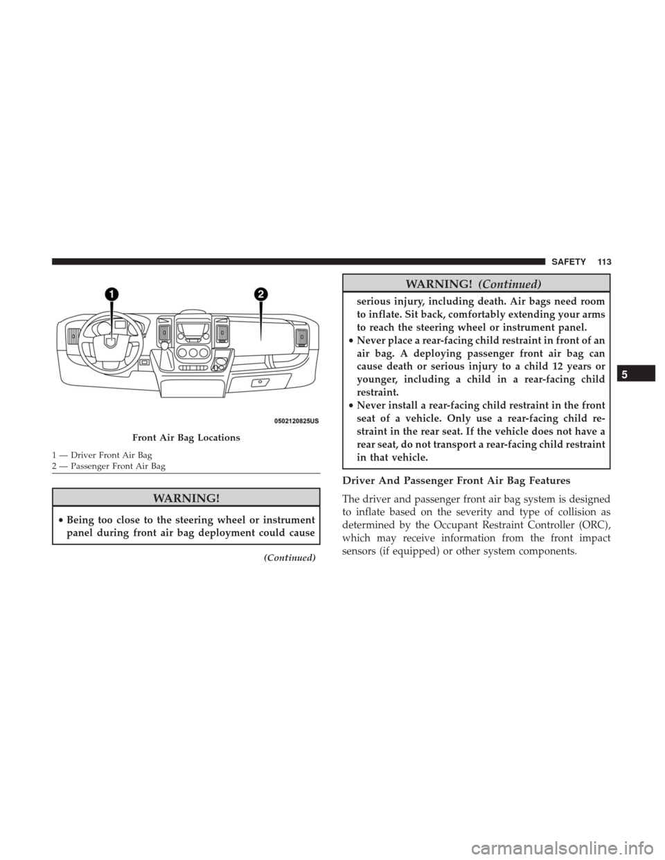
Front Air Bags
This vehicle has front air bags and lap/shoulder belts for
both the driver and front passenger. The front air bags are
a supplement to the seat belt restraint systems. The driver
front air bag is mounted in the center of the steering wheel.
The passenger front air bag is mounted in the instrument
panel, above the glove compartment. The words “SRS
AIRBAG” or “AIRBAG” are embossed on the air bag
covers.
112 SAFETY
Page 115 of 332
WARNING!
•Being too close to the steering wheel or instrument
panel during front air bag deployment could cause
(Continued)
WARNING! (Continued)
serious injury, including death. Air bags need room
to inflate. Sit back, comfortably extending your arms
to reach the steering wheel or instrument panel.
• Never place a rear-facing child restraint in front of an
air bag. A deploying passenger front air bag can
cause death or serious injury to a child 12 years or
younger, including a child in a rear-facing child
restraint.
• Never install a rear-facing child restraint in the front
seat of a vehicle. Only use a rear-facing child re-
straint in the rear seat. If the vehicle does not have a
rear seat, do not transport a rear-facing child restraint
in that vehicle.
Driver And Passenger Front Air Bag Features
The driver and passenger front air bag system is designed
to inflate based on the severity and type of collision as
determined by the Occupant Restraint Controller (ORC),
which may receive information from the front impact
sensors (if equipped) or other system components.
Front Air Bag Locations
1 — Driver Front Air Bag
2 — Passenger Front Air Bag
5
SAFETY 113
Page 116 of 332
WARNING!
•No objects should be placed over or near the air bag
on the instrument panel or steering wheel because
any such objects could cause harm if the vehicle is in
a collision severe enough to cause the air bag to
inflate.
• Do not put anything on or around the air bag covers
or attempt to open them manually. You may damage
the air bags and you could be injured because the air
bags may no longer be functional. The protective
covers for the air bag cushions are designed to open
only when the air bags are inflating.
• Relying on the air bags alone could lead to more
severe injuries in a collision. The air bags work with
your seat belt to restrain you properly. In some
collisions, air bags won’t deploy at all. Always wear
your seat belts even though you have air bags.
Front Air Bag Operation
Front Air Bags are designed to provide additional protec-
tion by supplementing the seat belts. Front air bags are not
expected to reduce the risk of injury in rear, side, or
rollover collisions. The front air bags will not deploy in all frontal collisions, including some that may produce sub-
stantial vehicle damage — for example, some pole colli-
sions, truck underrides, and angle offset collisions.
On the other hand, depending on the type and location of
impact, front air bags may deploy in crashes with little
vehicle front-end damage but that produce a severe initial
deceleration.
Because air bag sensors measure vehicle deceleration over
time, vehicle speed and damage by themselves are not
good indicators of whether or not an air bag should have
deployed.
Seat belts are necessary for your protection in all collisions,
and also are needed to help keep you in position, away
from an inflating air bag.
When the ORC detects a collision requiring the front air
bags, it signals the inflator units. A large quantity of
non-toxic gas is generated to inflate the front air bags.
The steering wheel hub trim cover and the upper passen-
ger side of the instrument panel separate and fold out of
the way as the air bags inflate to their full size. The front air
bags fully inflate in less time than it takes to blink your
eyes. The front air bags then quickly deflate while helping
to restrain the driver and front passenger.
114 SAFETY