Lights Ram ProMaster 2019 Owner's Guide
[x] Cancel search | Manufacturer: RAM, Model Year: 2019, Model line: ProMaster, Model: Ram ProMaster 2019Pages: 332, PDF Size: 3.66 MB
Page 122 of 332
•As the air bags deflate, you may see some smoke-like
particles. The particles are a normal by-product of the
process that generates the non-toxic gas used for air bag
inflation. These airborne particles may irritate the skin,
eyes, nose, or throat. If you have skin or eye irritation,
rinse the area with cool water. For nose or throat
irritation, move to fresh air. If the irritation continues,
see your doctor. If these particles settle on your clothing,
follow the garment manufacturer ’s instructions for
cleaning.
Do not drive your vehicle after the air bags have deployed.
If you are involved in another collision, the air bags will
not be in place to protect you.
WARNING!
Deployed air bags and seat belt pretensioners cannot
protect you in another collision. Have the air bags, seat
belt pretensioners, and the seat belt retractor assem-
blies replaced by an authorized dealer immediately.
Also, have the Occupant Restraint Controller System
serviced as well. NOTE:
•
Air bag covers may not be obvious in the interior trim,
but they will open during air bag deployment.
• After any collision, the vehicle should be taken to an
authorized dealer immediately.
Fuel Cut Off Switch
Your vehicle is equipped with a Fuel Cut Off switch. In the
event of an accident, if the communication network re-
mains intact, and the power remains intact, depending on
the nature of the event, the Fuel Cut Off Switch may
perform the following functions:
• Cut off fuel to the engine and turn off the engine.
• Flash hazard lights as long as the battery has power or
until the hazard light button is pressed. The hazard
lights can be deactivated by pressing the hazard light
button.
• Turn on the interior lights, which remain on as long as
the battery has power.
• Unlock the power door locks.
120 SAFETY
Page 123 of 332
NOTE:After an accident, remember to cycle the ignition to
the STOP (OFF/LOCK) position and remove the key from
the ignition switch to avoid draining the battery. Carefully
check the vehicle for fuel leaks in the engine compartment
and on the ground near the engine compartment and fuel
tank before resetting the system and starting the engine. If
there are no fuel leaks or damage to the vehicle electrical
devices (e.g. headlights) after an accident, reset the Fuel
Cut Off Switch by following the procedure described
below. If you have any doubt, contact an authorized dealer.
Fuel Cut Off Switch Reset Procedure
In order to reset the Fuel Cut Off Switch after an event
push the “A” Button located underneath the instrument
panel on the passenger side.
WARNING!
If, after an accident, you smell fuel or see leaks from
the fuel system, do not reset the Fuel Cut Off Switch to
avoid the risk of fire. Before resetting the Fuel Cut Off
Switch, carefully check for fuel leaks or damage to the
vehicle electrical devices (e.g. headlights).
Fuel Cut Off Switch
5
SAFETY 121
Page 135 of 332
WARNING!(Continued)
•If the vehicle carpet has been removed and re-
installed, always properly attach carpet to the floor
and check the floor mat fasteners are secure to the
vehicle carpet. Fully depress each pedal to check for
interference with the accelerator, brake, or clutch
pedals then re-install the floor mats.
• It is recommended to only use mild soap and water
to clean your floor mats. After cleaning, always check
your floor mat has been properly installed and is
secured to your vehicle using the floor mat fasteners
by lightly pulling mat.
Periodic Safety Checks You Should Make Outside
The Vehicle
Tires
Examine tires for excessive tread wear and uneven wear
patterns. Check for stones, nails, glass, or other objects
lodged in the tread or sidewall. Inspect the tread for cuts
and cracks. Inspect sidewalls for cuts, cracks, and bulges.
Check the wheel bolts for tightness. Check the tires (includ-
ing spare) for proper cold inflation pressure.
Lights
Have someone observe the operation of brake lights and
exterior lights while you work the controls. Check turn
signal and high beam indicator lights on the instrument
panel.
Door Latches
Check for proper closing, latching, and locking.
Fluid Leaks
Check area under the vehicle after overnight parking for
fuel, coolant, oil, or other fluid leaks. Also, if gasoline
fumes are detected or if fuel, or brake fluid leaks are
suspected. The cause should be located and corrected
immediately.
5
SAFETY 133
Page 158 of 332
While audible signals are emitted, the audio system is not
muted.
The audible signal is turned off immediately if the distance
increases. The tone cycle remains constant if the distance
measured by the inner sensors is constant. If this condition
occurs for the external sensors, the signal is turned off after
three seconds (stopping warnings during maneuvers par-
allel to walls).
ParkSense Rear Park Assist Failure Indications
A malfunction of the ParkSense Rear Park Assist sensors or
system is indicated, during REVERSE gear engagement, by
the instrument panel warning icon.The warning icon is illuminated and a message is
displayed in the instrument cluster display (if
equipped). Refer to “Warning Lights And Mes-
sages” in “Getting To Know Your Instrument
Panel” for further information.
The sensors and wiring are tested continuously when the
ignition is in the ON/RUN position. Failures are indicated
immediately if they occur when the system is ON.
Even if the system is able to identify that a specific sensor
is in failure condition, the instrument cluster display shall
indicate that the ParkSense Rear Park Assist system is unavailable, without reference to the sensor in failure
condition. If even a single sensor fails, the entire system
must be disabled. The system is turned off automatically.
Cleaning The ParkSense System
Clean the Rear Park Assist sensors with water, car wash
soap and a soft cloth. Do not use rough or hard cloths. In
washing stations, clean sensors quickly keeping the vapor
jet/high pressure washing nozzles at least 4 inches (10 cm)
from the sensors. Do not scratch or poke the sensors.
Otherwise, you could damage the sensors.
ParkSense Rear Park Assist System Usage
Precautions
NOTE:
•
Ensure that the outer surface and the underside of the
rear bumper is clean and clear of snow, ice, mud, dirt or
other obstruction to keep the Rear Park Assist system
operating properly.
• Jackhammers, large trucks, and other vibrations could
affect the performance of Rear Park Assist.
• Clean the Rear Park Assist sensors regularly, taking care
not to scratch or damage them. The sensors must not be
covered with ice, snow, slush, mud, dirt or debris.
156 STARTING AND OPERATING
Page 172 of 332
WARNING!
•Do not connect trailer brakes to your vehicle’s hy-
draulic brake lines. It can overload your brake sys-
tem and cause it to fail. You might not have brakes
when you need them and could have an accident.
• Towing any trailer will increase your stopping dis-
tance. When towing, you should allow for additional
space between your vehicle and the vehicle in front
of you. Failure to do so could result in an accident.
CAUTION!
If the trailer weighs more than 1,000 lbs (453 kg)
loaded, it should have its own brakes and they should
be of adequate capacity. Failure to do this could lead to
accelerated brake lining wear, higher brake pedal
effort, and longer stopping distances.
Towing Requirements — Trailer Lights And Wiring
Whenever you pull a trailer, regardless of the trailer size,
stoplights and turn signals on the trailer are required for
motoring safety. The Trailer Tow Package may include a four- and seven-pin
wiring harness. Use a factory approved trailer harness and
connector.
NOTE:
Do not cut or splice wiring into the vehicle’s wiring
harness.
The electrical connections are all complete to the vehicle
but you must mate the harness to a trailer connector. Refer
to the following illustrations.
Trailer Electrical Connector Location
1 — Four-Pin Connector Location
2 — Seven-Pin Connector Location
170 STARTING AND OPERATING
Page 193 of 332
CavityMini Fuse Description
F31 5 Amp Beige INT/A
F34 7.5 Amp Brown Clearance Lights
F36 15 Amp Blue +30 (ACM – TPCU – RRM – DLC)
F37 5 Amp Beige INT (BRAKE NO – IPC)
Fuse Panel Cavity Locations
7
IN CASE OF EMERGENCY 191
Page 227 of 332
SCHEDULED SERVICING
Your vehicle is equipped with an automatic oil change
indicator system. The oil change indicator system will
remind you that it is time to take your vehicle in for
scheduled maintenance.
Based on engine operation conditions, the oil change
indicator message will illuminate in the instrument cluster.
This means that service is required for your vehicle.
Operating conditions such as frequent short-trips, trailer
tow, and extremely hot or cold ambient temperatures will
influence when the “Oil Change Required” message is
displayed. Severe Operating Conditions can cause the
change oil message to illuminate as early as 3,500 miles
(5,600 km) since last reset. Have your vehicle serviced as
soon as possible, within the next 500 miles (805 km).
Your authorized dealer will reset the oil change indicator
message after completing the scheduled oil change. If a
scheduled oil change is performed by someone other than
your authorized dealer, the message can be reset by
referring to the steps described under “Instrument Cluster
Display” in “Getting To Know Your Instrument Panel” for
further information.NOTE:
Under no circumstances should oil change inter-
vals exceed 10,000 miles (16,000 km), twelve months or 350
hours of engine run time, whichever comes first. The 350
hours of engine run or idle time is generally only a concern
for fleet customers.
Severe Duty All Models
Change Engine Oil at 4,000 miles (6,500 km) or 350 hours of
engine run time if the vehicle is operated in a dusty and off
road environment or is operated predominately at idle or
only very low engine RPM’s. This type of vehicle use is
considered Severe Duty.
Once A Month Or Before A Long Trip:
• Check engine oil level.
• Check windshield washer fluid level.
• Check the tire inflation pressures and look for unusual
wear or damage. Rotate at the first sign of irregular
wear, even if it occurs before the oil indicator system
turns on.
• Check the fluid levels of the coolant reservoir, brake
master cylinder, and power steering and fill as needed.
• Check function of all interior and exterior lights.
8
SERVICING AND MAINTENANCE 225
Page 272 of 332
The most common causes are:
•Road salt, dirt and moisture accumulation.
• Stone and gravel impact.
• Insects, tree sap and tar.
• Salt in the air near seacoast localities.
• Atmospheric fallout/industrial pollutants.
Body And Underbody Maintenance
Cleaning Headlights
Your vehicle is equipped with plastic headlights and fog
lights that are lighter and less susceptible to stone breakage
than glass headlights.
Plastic is not as scratch resistant as glass and therefore
different lens cleaning procedures must be followed.
To minimize the possibility of scratching the lenses and
reducing light output, avoid wiping with a dry cloth. To
remove road dirt, wash with a mild soap solution followed
by rinsing.
Do not use abrasive cleaning components, solvents, steel
wool or other aggressive material to clean the lenses.
Preserving The Bodywork
Washing
•Wash your vehicle regularly. Always wash your vehicle
in the shade using Mopar Car Wash, or a mild car wash
soap, and rinse the panels completely with clear water.
• If insects, tar, or other similar deposits have accumulated
on your vehicle, use Mopar Super Kleen Bug and Tar
Remover to remove.
• Use a high quality cleaner wax, such as Mopar Cleaner
Wax to remove road film, stains and to protect your
paint finish. Take care never to scratch the paint.
• Avoid using abrasive compounds and power buffing
that may diminish the gloss or thin out the paint finish.
CAUTION!
• Do not use abrasive or strong cleaning materials such
as steel wool or scouring powder that will scratch
metal and painted surfaces.
• Use of power washers exceeding 1,200 psi (8,274 kPa)
can result in damage or removal of paint and decals.
270 SERVICING AND MAINTENANCE
Page 290 of 332
NOTE:The NAV button in the middle of your Uconnect
system may also contain the word COMPASS.
Uconnect 3/3 NAV Settings
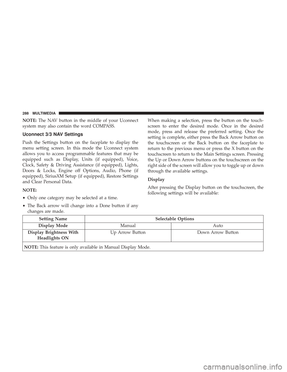
Push the Settings button on the faceplate to display the
menu setting screen. In this mode the Uconnect system
allows you to access programmable features that may be
equipped such as Display, Units (if equipped), Voice,
Clock, Safety & Driving Assistance (if equipped), Lights,
Doors & Locks, Engine off Options, Audio, Phone (if
equipped), SiriusXM Setup (if equipped), Restore Settings
and Clear Personal Data.
NOTE:
• Only one category may be selected at a time.
• The Back arrow will change into a Done button if any
changes are made. When making a selection, press the button on the touch-
screen to enter the desired mode. Once in the desired
mode, press and release the preferred setting. Once the
setting is complete, either press the Back Arrow button on
the touchscreen or the Back button on the faceplate to
return to the previous menu or press the X button on the
touchscreen to return to the Main Settings screen. Pressing
the Up or Down Arrow buttons on the touchscreen on the
right side of the screen will allow you to toggle up or down
through the available settings.
Display
After pressing the Display button on the touchscreen, the
following settings will be available:
Setting Name
Selectable Options
Display Mode Manual Auto
Display Brightness With Headlights ON Up Arrow Button
Down Arrow Button
NOTE: This feature is only available in Manual Display Mode.
288 MULTIMEDIA
Page 291 of 332
Setting NameSelectable Options
Display Brightness With the Headlights Off Up Arrow Button
Down Arrow Button
NOTE: This feature is only available in Manual Display Mode.
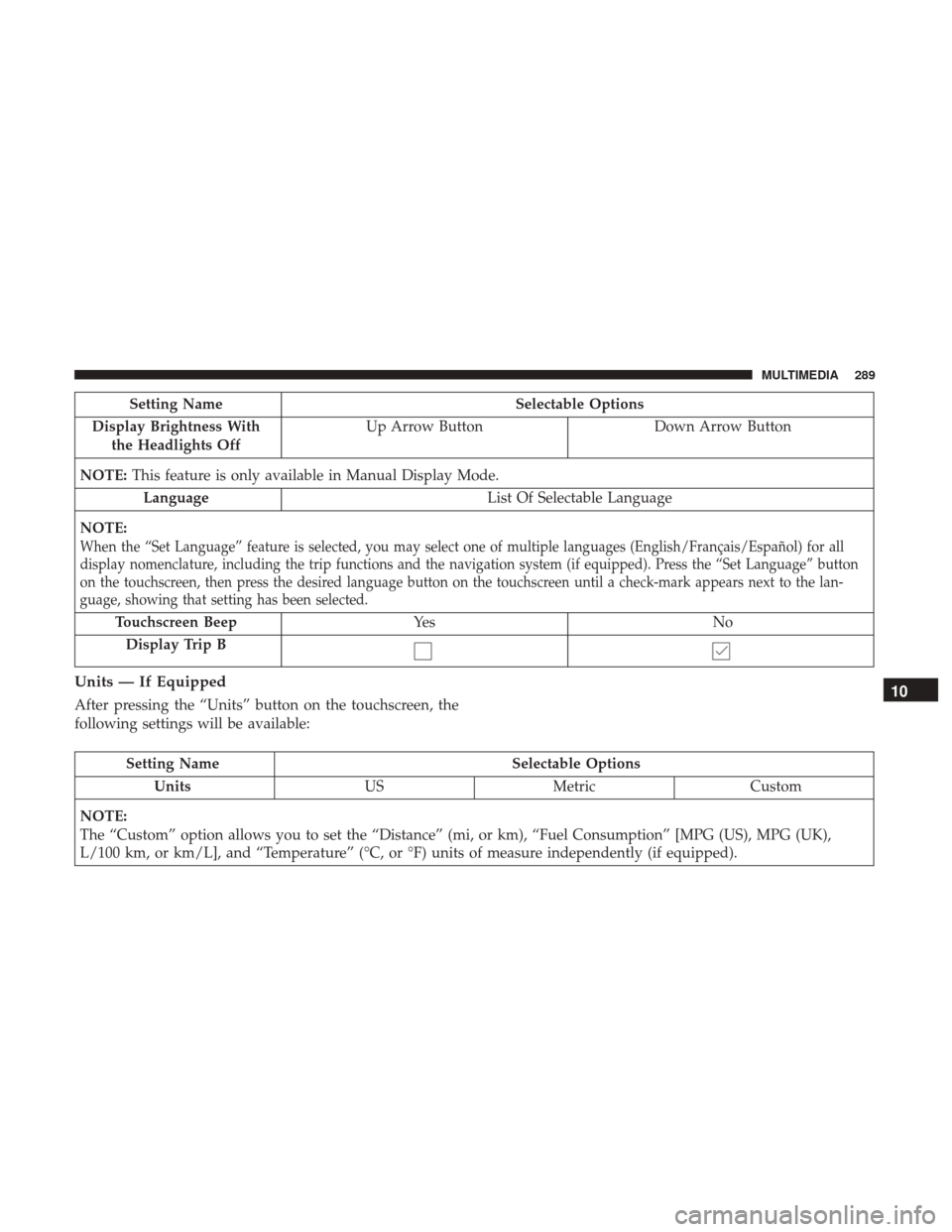
Language List Of Selectable Language
NOTE:
When the “Set Language” feature is selected, you may select one of multiple languages (English/Français/Español) for all
display nomenclature, including the trip functions and the navigation system (if equipped). Press the “Set Language” button
on the touchscreen, then press the desired language button on the touchscreen until a check-mark appears next to the lan-
guage, showing that setting has been selected.
Touchscreen Beep Ye s N o
Display Trip B
Units — If Equipped
After pressing the “Units” button on the touchscreen, the
following settings will be available:
Setting Name Selectable Options
Units USMetric Custom
NOTE:
The “Custom” option allows you to set the “Distance” (mi, or km), “Fuel Consumption” [MPG (US), MPG (UK),
L/100 km, or km/L], and “Temperature” (°C, or °F) units of measure independently (if equipped).
10
MULTIMEDIA 289