Speed Ram ProMaster 2020 Owner's Manual
[x] Cancel search | Manufacturer: RAM, Model Year: 2020, Model line: ProMaster, Model: Ram ProMaster 2020Pages: 264, PDF Size: 10.11 MB
Page 5 of 264

3
GETTING TO KNOW YOUR INSTRUMENT
PANEL
INSTRUMENT CLUSTER .......................................... 41
Instrument Cluster Descriptions........................ 42
INSTRUMENT CLUSTER DISPLAY ......................... 43
Location And Controls ........................................ 43
Change Engine Oil .............................................. 44
Display Setup Menu ........................................... 44
Values Displayed ................................................ 45
Personal Settings (Customer-Programmable
Features) ............................................................. 46
TRIP COMPUTER ..................................................... 46
Trip Button .......................................................... 46
Trip Functions ..................................................... 46
WARNING LIGHTS AND MESSAGES ..................... 47
Red Warning Lights ............................................ 47
Yellow Warning Lights ........................................ 50
Yellow Indicator Lights ....................................... 52
Green Indicator Lights ........................................ 53
Blue Indicator Lights .......................................... 53
ONBOARD DIAGNOSTIC SYSTEM — OBD II ........ 54
Onboard Diagnostic System (OBD II)
Cybersecurity ...................................................... 54
EMISSIONS INSPECTION AND MAINTENANCE
PROGRAMS ............................................................. 55
SAFETY
SAFETY FEATURES ..................................................56
Four-Wheel Anti-Lock Brake System (ABS) ....... 56
Electronic Brake Control (EBC) System ........... 57
AUXILIARY DRIVING SYSTEMS ..............................61
Tire Pressure Monitoring System (TPMS) ......... 61
OCCUPANT RESTRAINT SYSTEMS .......................64
Occupant Restraint Systems Features ............ 64
Important Safety Precautions............................ 65
Seat Belt Systems ............................................. 66
Supplemental Restraint Systems (SRS) ........... 73
Child Restraints .................................................. 83
Transporting Pets .............................................. 89
SAFETY TIPS ............................................................89
Transporting Passengers ................................... 89
Exhaust Gas ........................................................ 89
Safety Checks You Should Make Inside
The Vehicle ........................................................ 90 Periodic Safety Checks You Should Make
Outside The Vehicle ........................................... 91
STARTING AND OPERATING
STARTING THE ENGINE ..........................................92
Automatic Transmission .................................... 92
Normal Starting .................................................. 92
Cold Weather Operation
(Below –22°F Or −30°C) ................................. 92 If Engine Fails To Start ....................................... 92
After Starting ...................................................... 93
ENGINE BLOCK HEATER — IF EQUIPPED ............ 93
ENGINE BREAK-IN RECOMMENDATIONS ........... 93
PARKING BRAKE ................................................... 94
AUTOMATIC TRANSMISSION ................................ 95
Key Ignition Park Interlock .................................96
Brake/Transmission Shift Interlock System ....96
Six-Speed Automatic Transmission ...................96
POWER STEERING ............................................... 102
Power Steering Fluid Check ........................... 103
SPEED CONTROL — IF EQUIPPED ......................103
To Activate ........................................................ 103
To Set A Desired Speed ................................... 104
To Vary The Speed Setting .............................. 104
To Accelerate For Passing ............................... 105
To Resume Speed ............................................ 105
To Deactivate ................................................... 105
PARKSENSE REAR PARK ASSIST —
IF EQUIPPED ..........................................................105
ParkSense Rear Park Assist Sensors ............. 106
ParkSense Rear Park Assist Alerts ................. 106
ParkSense Rear Park Assist Failure
Indications ........................................................ 108 Cleaning The ParkSense System .................... 108
ParkSense Rear Park Assist System Usage
Precautions ...................................................... 108
PARKVIEW REAR BACK UP CAMERA ............... 109
REFUELING THE VEHICLE.....................................111
Loose Fuel Filler Cap Message ....................... 111
20_VF_OM_EN_US_t.book Page 3
Page 17 of 264
GETTING TO KNOW YOUR VEHICLE15
(Continued)
Auto Unlock Doors
This feature unlocks all front doors when one
front door is opened.
NOTE:
If the rear or side door is open, only the rear or
side door is unlocked.
Automatic Door Locks
When enabled, the door locks will lock automat -
ically when the vehicle's speed exceeds 12 mph
(20 km/h). The auto door lock feature can be
enabled or disabled through the Uconnect
system.
SEATS
Seats are a part of the Occupant Restraint
System of the vehicle.
Manual Adjustments
The driver and passenger seats can be adjusted
forward/rearward and reclined. Front and rear
height and lumbar can also be adjusted (if
equipped).
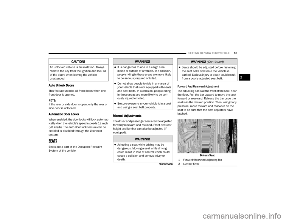
Forward And Rearward Adjustment
The adjusting bar is at the front of the seat, near
the floor. Pull the bar upward to move the seat
forward or rearward. Release the bar once the
seat is in the desired position. Then, using body
pressure, move forward and rearward on the
seat to be sure that the seat adjusters have
latched.
Driver’s Seat
CAUTION!
An unlocked vehicle is an invitation. Always
remove the key from the ignition and lock all
of the doors when leaving the vehicle
unattended.
WARNING!
It is dangerous to ride in a cargo area,
inside or outside of a vehicle. In a collision,
people riding in these areas are more likely
to be seriously injured or killed.
Do not allow people to ride in any area of
your vehicle that is not equipped with seats
and seat belts. In a collision, people riding
in these areas are more likely to be seri -
ously injured or killed.
Be sure everyone in your vehicle is in a seat
and using a seat belt properly.
WARNING!
Adjusting a seat while driving may be
dangerous. Moving a seat while driving
could result in loss of control which could
cause a collision and serious injury or
death.
Seats should be adjusted before fastening
the seat belts and while the vehicle is
parked. Serious injury or death could result
from a poorly adjusted seat belt.
1 — Forward/Rearward Adjusting Bar
2 — Lumbar Knob
WARNING!
(Continued)
2
20_VF_OM_EN_US_t.book Page 15
Page 30 of 264
28GETTING TO KNOW YOUR VEHICLE
Intermittent Wiper System
Push the lever downward to the first detent and
rotate the center ring to use one of the four
intermittent wiper settings when weather condi -
tions make a single wiping cycle, with a variable
delay between cycles, desirable.
Low Speed
Push the lever downward to the second detent.
The wipers will operate at low speed.
High Speed
Push the lever downward to the third detent.
The wipers will operate at high speed.
Windshield Washer Operation
To use the washer, pull the windshield wiper/
washer lever toward the steering wheel to acti -
vate. The wipers will activate automatically for
three cycles after the lever is released, and then
resume the intermittent interval previously
selected.
If the lever is pulled while in the off position, the
wipers will operate for three cycles and then
turn off.
Mist Feature
Use the Mist feature when weather conditions
make occasional usage of the wipers neces -
sary. Push the lever upward to the MIST position
and release for a single wiping cycle.
NOTE:
The mist feature does not activate the washer
pump; therefore, no washer fluid will be sprayed
on the windshield. The wash function must be
used in order to spray the windshield with
washer fluid.
CLIMATE CONTROLS
The Climate Control System allows you to regu -
late the temperature, air flow, and direction of
air circulating throughout the vehicle. The
controls are located on the touchscreen (if
equipped) and on the instrument panel below
the radio.
Manual Climate Control Overview
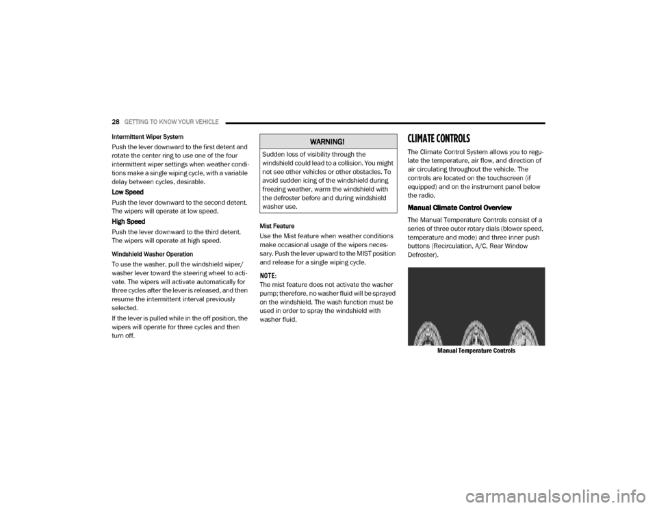
The Manual Temperature Controls consist of a
series of three outer rotary dials (blower speed,
temperature and mode) and three inner push
buttons (Recirculation, A/C, Rear Window
Defroster).
Manual Temperature Controls
WARNING!
Sudden loss of visibility through the
windshield could lead to a collision. You might
not see other vehicles or other obstacles. To
avoid sudden icing of the windshield during
freezing weather, warm the windshield with
the defroster before and during windshield
washer use.
20_VF_OM_EN_US_t.book Page 28
Page 32 of 264
30GETTING TO KNOW YOUR VEHICLE
Blower Control
Blower Control regulates the amount of air forced through the climate system. There are seven blower speeds available.
The blower speed increases as you turn the blower control knob clockwise from the lowest blower setting. The blower
speed decreases as you turn the blower control knob counterclockwise.
NOTE:
Depending on the configuration, your vehicle may be equipped with four blower speeds.
Mode Control
Turn the mode control knob to change the airflow distribution mode. The airflow distribution mode can be adjusted so air
comes from the instrument panel outlets, floor outlets, defrost outlets and demist outlets. The Mode settings are as
follows:
Panel Mode Panel Mode Air comes from the outlets in the instrument panel. Each of these outlets can be individually adjusted to direct the flow of
air. The air vanes of the center outlets and outboard outlets can be moved up and down or side to side to regulate airflow
direction. There is a shut off wheel located below the air vents to shut off or adjust the amount of airflow from these
outlets.
Icon Description
20_VF_OM_EN_US_t.book Page 30
Page 35 of 264

GETTING TO KNOW YOUR VEHICLE33
Climate Control Functions
A/C (Air Conditioning)
The Air Conditioning (A/C) button allows the
operator to manually activate or deactivate the
air conditioning system. When the air condi -
tioning system is turned on, cool dehumidified
air will flow through the outlets into the cabin.
For improved fuel economy, press the A/C
button to turn off the air conditioning and manu -
ally adjust the blower and airflow mode settings.
Also, make sure to select only Panel, Bi-Level or
Floor modes.
NOTE:
For Manual Climate Controls, if the system is
in Mix, Floor or Defrost Mode, the A/C can be
turned off, but the A/C system shall remain
active to prevent fogging of the windows.
If fog or mist appears on the windshield or
side glass, select Defrost mode, and increase
blower speed if needed.
If your air conditioning performance seems
lower than expected, check the front of the
A/C condenser (located in front of the radi -
ator), for an accumulation of dirt or insects.
Clean with a gentle water spray from the front
of the radiator and through the condenser.
Recirculation
In cold weather, use of Recirculation mode may
lead to excessive window fogging. The Recircu -
lation feature may be unavailable if conditions
exist that could create fogging on the inside of
the windshield. On systems with Manual
Climate Controls, the Recirculation mode is not
allowed in Defrost mode to improve window
clearing operation. Recirculation is disabled
automatically if this mode is selected.
Attempting to use Recirculation while in this
mode causes the LED in the control button to
blink and then turns off.
Operating Tips
NOTE:
Refer to the chart at the end of this section for
suggested control settings for various weather
conditions.
Summer Operation
The engine cooling system must be protected
with a high-quality antifreeze coolant to provide
proper corrosion protection and to protect
against engine overheating. A solution of 50%
OAT (Organic Additive Technology) coolant that
meets the requirements of FCA Material Stan -dard MS.90032 and 50% water is recom
-
mended. Refer to “Fluids And Lubricants” in
“Technical Specifications” for proper coolant
selection.
Winter Operation
Use of the air Recirculation mode during Winter
months is not recommended because it may
cause window fogging.
Vacation Storage
Any time you store your vehicle or keep it out of
service (i.e., vacation) for two weeks or more,
run the air conditioning system at idle for about
five minutes in the fresh air and high blower
setting. This will ensure adequate system lubri -
cation to minimize the possibility of compressor
damage when the system is started again.
Window Fogging
Interior fogging on the windshield can be quickly
removed by turning the mode selector to
Defrost. The Defrost/Floor mode can be used to
maintain a clear windshield and provide suffi -
cient heating. If side window fogging becomes a
problem increase blower speed. Vehicle
windows tend to fog on the inside in mild but
rainy or humid weather.
2
20_VF_OM_EN_US_t.book Page 33
Page 44 of 264
42GETTING TO KNOW YOUR INSTRUMENT PANEL
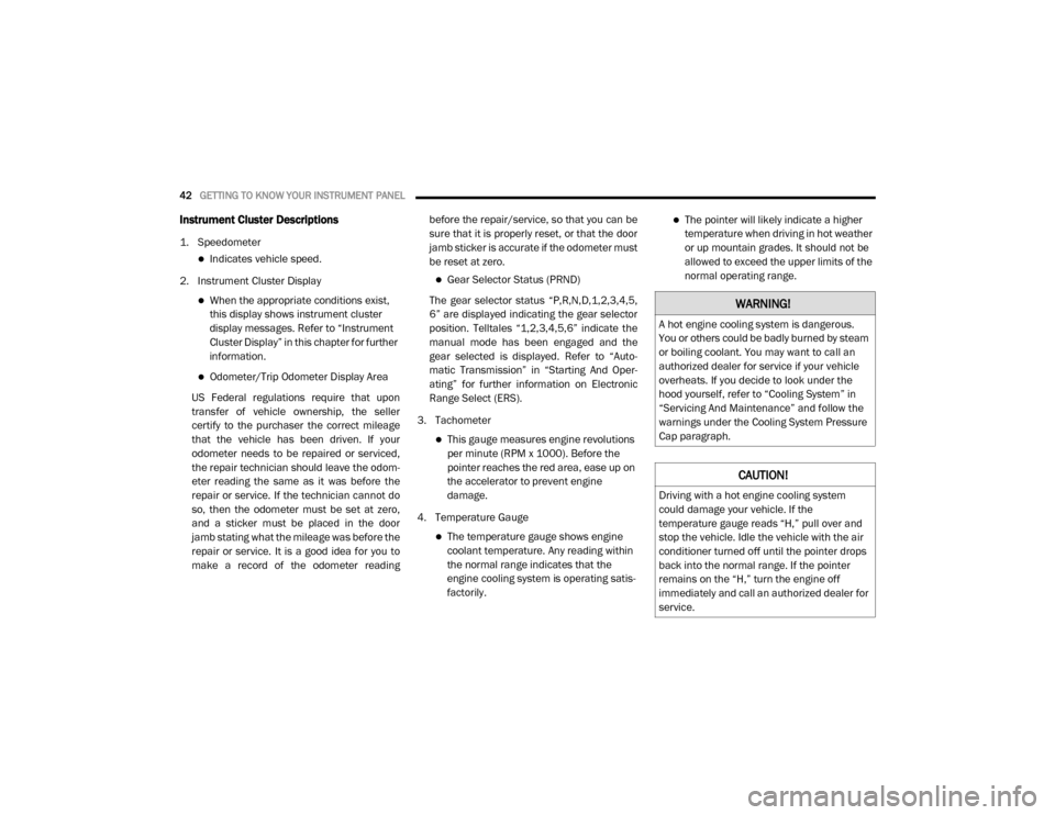
Instrument Cluster Descriptions
1. Speedometer
Indicates vehicle speed.
2. Instrument Cluster Display
When the appropriate conditions exist,
this display shows instrument cluster
display messages. Refer to “Instrument
Cluster Display” in this chapter for further
information.
Odometer/Trip Odometer Display Area
US Federal regulations require that upon
transfer of vehicle ownership, the seller
certify to the purchaser the correct mileage
that the vehicle has been driven. If your
odometer needs to be repaired or serviced,
the repair technician should leave the odom -
eter reading the same as it was before the
repair or service. If the technician cannot do
so, then the odometer must be set at zero,
and a sticker must be placed in the door
jamb stating what the mileage was before the
repair or service. It is a good idea for you to
make a record of the odometer reading before the repair/service, so that you can be
sure that it is properly reset, or that the door
jamb sticker is accurate if the odometer must
be reset at zero.
Gear Selector Status (PRND)
The gear selector status “P,R,N,D,1,2,3,4,5,
6” are displayed indicating the gear selector
position. Telltales “1,2,3,4,5,6” indicate the
manual mode has been engaged and the
gear selected is displayed. Refer to “Auto -
matic Transmission” in “Starting And Oper -
ating” for further information on Electronic
Range Select (ERS).
3. Tachometer
This gauge measures engine revolutions
per minute (RPM x 1000). Before the
pointer reaches the red area, ease up on
the accelerator to prevent engine
damage.
4. Temperature Gauge
The temperature gauge shows engine
coolant temperature. Any reading within
the normal range indicates that the
engine cooling system is operating satis-
factorily.
The pointer will likely indicate a higher
temperature when driving in hot weather
or up mountain grades. It should not be
allowed to exceed the upper limits of the
normal operating range.
WARNING!
A hot engine cooling system is dangerous.
You or others could be badly burned by steam
or boiling coolant. You may want to call an
authorized dealer for service if your vehicle
overheats. If you decide to look under the
hood yourself, refer to “Cooling System” in
“Servicing And Maintenance” and follow the
warnings under the Cooling System Pressure
Cap paragraph.
CAUTION!
Driving with a hot engine cooling system
could damage your vehicle. If the
temperature gauge reads “H,” pull over and
stop the vehicle. Idle the vehicle with the air
conditioner turned off until the pointer drops
back into the normal range. If the pointer
remains on the “H,” turn the engine off
immediately and call an authorized dealer for
service.
20_VF_OM_EN_US_t.book Page 42
Page 45 of 264
GETTING TO KNOW YOUR INSTRUMENT PANEL43
5. Fuel Gauge
The pointer shows the level of fuel in the
fuel tank when the ignition switch is in
the ON/RUN position.
The fuel pump symbol points to the
side of the vehicle where the fuel door is
located.
INSTRUMENT CLUSTER DISPLAY
Your vehicle will be equipped with an instru -
ment cluster display, which offers useful infor -
mation to the driver. With the ignition in the
STOP (OFF/LOCK) mode, opening/closing of a
door will activate the display for viewing, and
display the total miles, or kilometers, in the
odometer. Your instrument cluster display is
designed to display important information
about your vehicle’s systems and features.
Using a driver interactive display located on the
instrument panel, your instrument cluster
display can show you how systems are working
and give you warnings when they are not. The
steering wheel mounted controls allow you to
scroll through the main menus and submenus.
You can access the specific information you
want and make selections and adjustments.
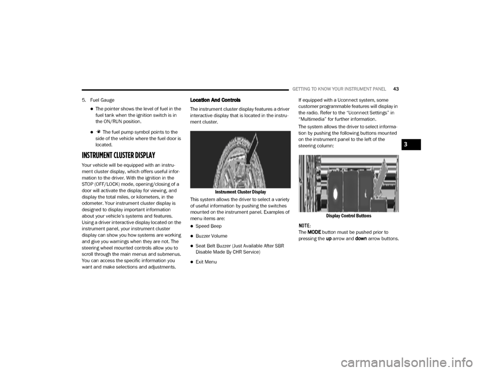
Location And Controls
The instrument cluster display features a driver
interactive display that is located in the instru -
ment cluster.
Instrument Cluster Display
This system allows the driver to select a variety
of useful information by pushing the switches
mounted on the instrument panel. Examples of
menu items are:
Speed Beep
Buzzer Volume
Seat Belt Buzzer (Just Available After SBR
Disable Made By CHR Service)
Exit Menu If equipped with a Uconnect system, some
customer programmable features will display in
the radio. Refer to the “Uconnect Settings” in
“Multimedia” for further information.
The system allows the driver to select informa
-
tion by pushing the following buttons mounted
on the instrument panel to the left of the
steering column:
Display Control Buttons
NOTE:
The MODE button must be pushed prior to
pressing the up arrow and down arrow buttons.
3
20_VF_OM_EN_US_t.book Page 43
Page 46 of 264
44GETTING TO KNOW YOUR INSTRUMENT PANEL
MODE Button
Push and hold the MODE button for a time
longer than one second to access/select the
information screens or submenu screens of a
main menu item. Push and hold the MODE
button for two seconds to reset displayed/
selected features that can be reset.
Up Arrow Button
Push and release the up arrow
button to scroll upward through the
main menu and submenus or
adjust the illumination on the
instrument panel when the headlights are on.
Down Arrow Button
Push and release the down arrow
button to scroll downward through
the main menu and submenus or
adjust the illumination on the
instrument panel when the headlights are on.
Change Engine Oil
Your vehicle is equipped with an engine oil
change indicator system. The “Change Engine
Oil” message will display in the instrument
cluster display. The engine oil change indicator
system is duty cycle based, which means the engine oil change interval may fluctuate, depen
-
dent upon your personal driving style.
Unless reset, this message will continue to
display each time you turn the ignition switch to
the ON/RUN position. To turn off the message
temporarily, push and release the MODE
button. To reset the oil change indicator system
(after performing the scheduled maintenance),
refer to the following procedure.
1. Turn the ignition switch to the ON position (do not start the engine).
2. Fully push the accelerator pedal slowly, three times, within 10 seconds.
3. Turn the ignition switch to the OFF/LOCK position.
NOTE:
If the indicator message illuminates when you
start the vehicle, the oil change indicator
system did not reset. If necessary, repeat this
procedure.Display Setup Menu
The menu comprises a series of functions
arranged in a cycle. Push and release the up or
down arrow button to access the different
options and settings (setup). The setup menu can be activated by pushing
the
MODE button. Single pushes on the up or
down arrow button will scroll through the setup
menu options. The menu items include the
following functions:
Speed Beep
Buzzer Volume
Seat Belt Buzzer (Just Available After SBR
Disable Made By CHR Service)
Exit menu
NOTE:
If equipped, some customer programmable
features will display in the Uconnect system.
Refer to your Uconnect Owner’s Manual Supple -
ment for further information.
Selecting An Option Of The Main Menu Without
Submenu
1. Briefly push and release the MODE button
to select the main menu option to set.
2. Push and release the up or down arrow
button (by single pushes) to select the new
setting.
20_VF_OM_EN_US_t.book Page 44
Page 47 of 264

GETTING TO KNOW YOUR INSTRUMENT PANEL45
3. Briefly push and release the MODE button
to store the new setting and go back to the
main menu option previously selected.
Selecting An Option Of The Main Menu With
Submenu
1. Briefly push and release the MODE button
to display the first submenu option.
2. Push and release the up or down arrow
button (by single pushes) to scroll through
all the submenu options.
3. Briefly push and release the MODE button
to select the displayed submenu option and
to open the relevant setup menu.
4. Push and release the up or down arrow
button (by single pushes) to select the new
setting for this submenu option.
5. Briefly push and release the MODE button
to store the new setting and go back to the
previously selected submenu option.
6. Push and release and hold the MODE
button to return to the main menu (short
hold) or the main screen (longer hold).Values Displayed
NOTE:
All of the following items are accessed by
pressing the TRIP button.
Range
This indicates the distance which may be trav -
eled with the fuel remaining in the tank,
assuming that driving conditions will not
change. The message “----” will appear on the
display in the following cases:
Distance less than 30 miles (or 50 km).
The vehicle is parked for a long time with the
engine running.
NOTE:
The range depends on several factors: driving
style, type of route (freeway, residential, moun -
tain roads, etc.), conditions of use of the vehicle
(load, tire pressure, etc.). Trip planning must
take into account the above notes.
Travel Distance
This value shows the distance covered since the
last reset.
Average Fuel Consumption
This value shows the approximate average
consumption since the last reset.
Current Fuel Consumption
This indicates the fuel consumption. The value
is constantly updated. The message “----” will
appear on the display if the vehicle is parked
with the engine running.
Average Speed
This value shows the vehicle's average speed as
a function of the overall time elapsed since the
last reset.
Travel Time
This value shows the time elapsed since the last
reset.
3
20_VF_OM_EN_US_t.book Page 45
Page 48 of 264

46GETTING TO KNOW YOUR INSTRUMENT PANEL
Personal Settings
(Customer-Programmable Features)
Speed Beep
Buzzer Volume
Seat Belt Buzzer (Just Available After SBR
Disable Made By CHR Service)
Exit Menu
NOTE:
If equipped, some customer programmable
features will display in the Uconnect system.
Refer to “Uconnect Settings” in “Multimedia”
for further information.
TRIP COMPUTER
The Trip Computer is located in the instrument
cluster. It features a driver-interactive display
(displays information such as trip information,
range, fuel consumption, average speed, and
travel time).
NOTE:
The Uconnect System also has a Trip Computer
display and menus to customize the informa -
tion displayed in the cluster. For further infor -
mation, refer to “Uconnect Settings” in
“Multimedia”.
Trip Button
The TRIP button, located on the right steering
column stalk, can be used to display and to
reset the previously described values.
A short button push displays the different
values.
A long button push resets the system and
then starts a new trip.
New Trip
To reset:
Push and hold the TRIP button to reset the
system manually.
When the “Trip distance” reaches
99999.9 miles or kilometers or when the
“Travel time” reaches 999.59 (999 hours
and 59 minutes), the system is reset auto -
matically.
Disconnecting/Reconnecting the battery
resets the system.
NOTE:
If the reset operation occurs in the presence of
the screens concerning Trip A or Trip B, only the
information associated with Trip A or Trip B
functions will be reset. Start Of Trip Procedure
With the ignition on, push and hold the TRIP
button for over two seconds to reset trip infor
-
mation.
Exit Trip
To exit the Trip function, push the TRIP button
until all the trip menu items have been
displayed and the display returns to the main
menu.
Trip Functions
Both trip functions are resettable (reset — start
of new trip).
“Trip A” can be used to display the figures
relating to:
Trip Distance A
Average Fuel Consumption
Average Speed A
Travel Time A (Driving Time)
20_VF_OM_EN_US_t.book Page 46