length Ram ProMaster 2020 Owner's Manual
[x] Cancel search | Manufacturer: RAM, Model Year: 2020, Model line: ProMaster, Model: Ram ProMaster 2020Pages: 264, PDF Size: 10.11 MB
Page 23 of 264

GETTING TO KNOW YOUR VEHICLE21
STEERING WHEEL
Telescoping Steering Column
This feature allows you to lengthen or shorten
the steering column. The telescoping control
handle is located below the steering wheel at
the end of the steering column.
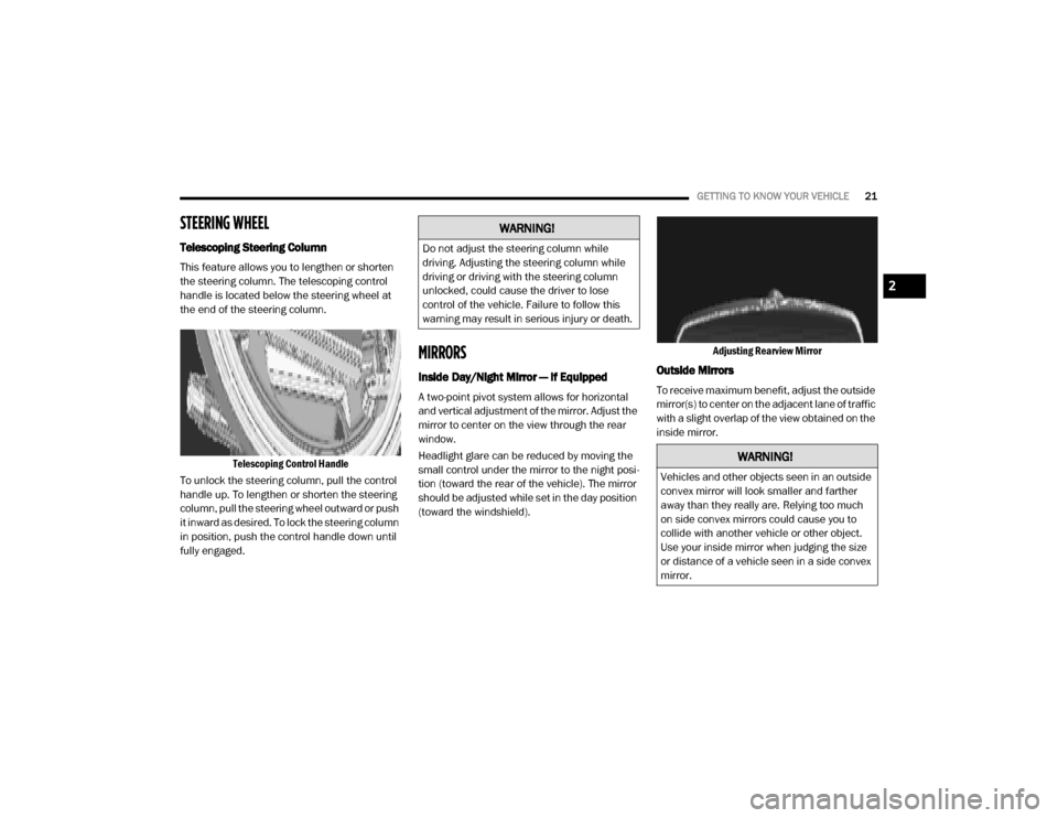
Telescoping Control Handle
To unlock the steering column, pull the control
handle up. To lengthen or shorten the steering
column, pull the steering wheel outward or push
it inward as desired. To lock the steering column
in position, push the control handle down until
fully engaged.
MIRRORS
Inside Day/Night Mirror — If Equipped
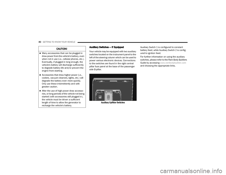
A two-point pivot system allows for horizontal
and vertical adjustment of the mirror. Adjust the
mirror to center on the view through the rear
window.
Headlight glare can be reduced by moving the
small control under the mirror to the night posi -
tion (toward the rear of the vehicle). The mirror
should be adjusted while set in the day position
(toward the windshield). Adjusting Rearview Mirror
Outside Mirrors
To receive maximum benefit, adjust the outside
mirror(s) to center on the adjacent lane of traffic
with a slight overlap of the view obtained on the
inside mirror.
WARNING!
Do not adjust the steering column while
driving. Adjusting the steering column while
driving or driving with the steering column
unlocked, could cause the driver to lose
control of the vehicle. Failure to follow this
warning may result in serious injury or death.
WARNING!
Vehicles and other objects seen in an outside
convex mirror will look smaller and farther
away than they really are. Relying too much
on side convex mirrors could cause you to
collide with another vehicle or other object.
Use your inside mirror when judging the size
or distance of a vehicle seen in a side convex
mirror.
2
20_VF_OM_EN_US_t.book Page 21
Page 42 of 264

40GETTING TO KNOW YOUR VEHICLE
Auxiliary Switches — If Equipped
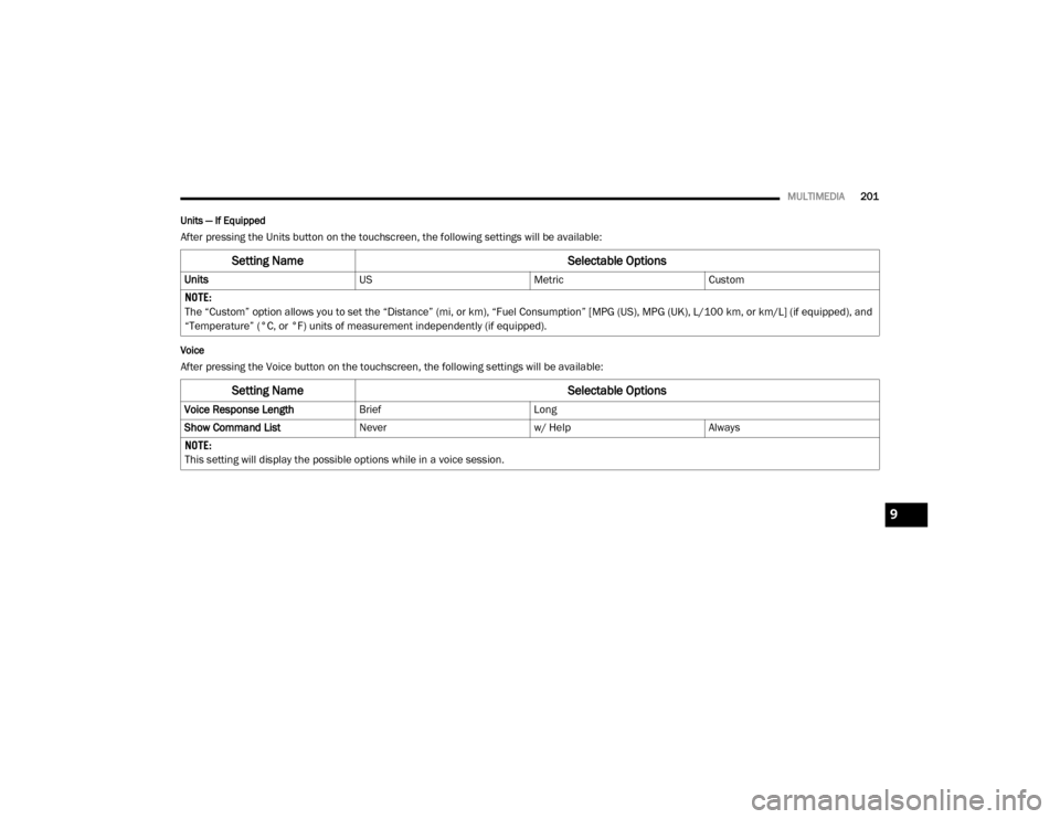
Your vehicle may be equipped with two auxiliary
switches located on the instrument panel to the
left of the steering column which can be used to
power various electronic devices. Connections
to the switches are found in the right central
pillar fuse panel at the base of the passenger
side B-pillar.
Auxiliary Upfitter Switches Auxiliary Switch 1 is configured to constant
battery feed, while Auxiliary Switch 2 is config
-
ured to ignition feed.
For further information on using the auxiliary
switches, please refer to the Ram Body Builders
Guide by accessing www.rambodybuilder.com
and choosing the appropriate links.CAUTION!
Many accessories that can be plugged in
draw power from the vehicle's battery, even
when not in use (i.e., cellular phones, etc.).
Eventually, if plugged in long enough, the
vehicle's battery will discharge sufficiently
to degrade battery life and/or prevent the
engine from starting.
Accessories that draw higher power (i.e.,
coolers, vacuum cleaners, lights, etc.) will
degrade the battery even more quickly.
Only use these intermittently and with
greater caution.
After the use of high power draw accesso -
ries, or long periods of the vehicle not being
started (with accessories still plugged in),
the vehicle must be driven a sufficient
length of time to allow the generator to
recharge the vehicle's battery.
20_VF_OM_EN_US_t.book Page 40
Page 203 of 264

MULTIMEDIA201
Units — If Equipped
After pressing the Units button on the touchscreen, the following settings will be available:
Voice
After pressing the Voice button on the touchscreen, the following settings will be available:
Setting Name Selectable Options
UnitsUSMetricCustom
NOTE:
The “Custom” option allows you to set the “Distance” (mi, or km), “Fuel Consumption” [MPG (US), MPG (UK), L/100 km, or km/L] (if equipped), and
“Temperature” (°C, or °F) units of measurement independently (if equipped).
Setting Name Selectable Options
Voice Response LengthBriefLong
Show Command List Neverw/ HelpAlways
NOTE:
This setting will display the possible options while in a voice session.
9
20_VF_OM_EN_US_t.book Page 201
Page 231 of 264

MULTIMEDIA229
3 — Route Bar
The Route Bar is shown when you have planned
a route. The Route Bar contains arrival informa-
tion, such as the estimated time of arrival, the
length of time to drive to the destination from
your current location, and information about the
next stop, if you have stops on your route. The
bottom of the Route Bar represents your current
location and shows the distance to the next
stop on your route.
4 — Current Location
This symbol shows your current location. Press
this symbol, or the speed panel, to mark your
current location.
5 — Speed Panel
Press this button to view the following informa -
tion (if available):
The speed limit at your location
The name of the street you are driving on NOTE:
If you drive more than 3 mph (5 km/h) over the
speed limit, the Speed Panel turns red. If you
drive less than 3 mph (5 km/h) over the speed
limit, the Speed Panel turns orange.
6 — Main Menu Button
Press the Main Menu Button to show the Main
Menu.
7 — Zoom Buttons
Press the zoom in + button to zoom in and the
zoom out – button to zoom out.
Advanced Lane Guidance
About Lane Guidance
NOTE:
Lane guidance is not available for all intersec
-
tions or in all countries.
Your navigation system helps you prepare for
highway exits and junctions by showing the
correct driving lane for your planned route. As you approach an exit or junction, the lane you
need is shown on the screen and in the instruc
-
tion panel.
Using Lane Guidance
There are two types of lane guidance:
Lane images
Instructions in the status bar
Lane Guidance
9
20_VF_OM_EN_US_t.book Page 229