tire size Ram ProMaster 2020 Owner's Manual
[x] Cancel search | Manufacturer: RAM, Model Year: 2020, Model line: ProMaster, Model: Ram ProMaster 2020Pages: 264, PDF Size: 10.11 MB
Page 6 of 264

4
VEHICLE LOADING ................................................112
Vehicle Certification Label ............................... 112
Gross Vehicle Weight Rating (GVWR) .............. 112
Gross Axle Weight Rating (GAWR) .................. 112
Tire Size .............................................................112
Rim Size ............................................................ 112
Inflation Pressure ............................................. 112
Curb Weight ...................................................... 112
Overloading ....................................................... 112
Loading .............................................................113
TRAILER TOWING ..................................................113
Common Towing Definitions ............................113
Trailer Hitch Classification ............................... 114
Trailer Towing Weights
(Maximum Trailer Weight Ratings) ................. 115 Trailer And Tongue Weight ..............................115Towing Requirements ..................................... 116
Towing Tips ...................................................... 118
RECREATIONAL TOWING
(BEHIND MOTORHOME, ETC.) ............................120
Towing This Vehicle Behind Another Vehicle .. 120
Recreational Towing ......................................... 120
DRIVING TIPS.........................................................121
Driving On Slippery Surfaces ..........................121
Driving Through Water ....................................121
IN CASE OF EMERGENCY
HAZARD WARNING FLASHERS ..........................123 BULB REPLACEMENT ........................................... 123
Replacement Bulbs .......................................... 123
Replacing Exterior Bulbs .................................. 125
Replacing Interior Bulbs .................................. 127
FUSES..................................................................... 128
Underhood Fuses ............................................. 128
Interior Fuses.................................................... 131
Right Central Pillar Fuses ................................ 132
JACKING AND TIRE CHANGING .......................... 133
Jack Location .................................................... 133
Spare Tire Removal .......................................... 134
Preparations For Jacking ................................. 135
Jacking Instructions ......................................... 136Wheel Covers .................................................... 139
TIRE SERVICE KIT — IF EQUIPPED ...................... 139
Tire Service Kit Storage ................................... 139
Tire Service Kit Components And Operation .. 140Tire Service Kit Usage Precautions ................. 140
Sealing A Tire With Tire Service Kit ................. 142
JUMP STARTING ................................................... 145
Preparations For Jump Start ........................... 145
Jump Starting Procedure ................................. 146
Battery Location ............................................... 147
IF YOUR ENGINE OVERHEATS ............................ 147
GEAR SELECTOR OVERRIDE .............................. 148FREEING A STUCK VEHICLE ............................... 149
TOWING A DISABLED VEHICLE........................... 149
Automatic Transmission .................................. 150
ENHANCED ACCIDENT RESPONSE SYSTEM
(EARS) ....................................................................151
EVENT DATA RECORDER (EDR) .......................... 151
SERVICING AND MAINTENANCE
SCHEDULED SERVICING .....................................152
Maintenance Plan ............................................ 152
Heavy Duty Use Of The Vehicle ....................... 155
ENGINE COMPARTMENT...................................... 156
3.6L Engine ..................................................... 156
Checking Oil Level — Gas Engine ................... 157
Adding Washer Fluid ........................................ 157Maintenance-Free Battery .............................. 157
Pressure Washing ............................................ 158
DEALER SERVICE ................................................. 158
Engine Oil ......................................................... 158Engine Oil Filter ................................................ 159
Engine Air Cleaner Filter ................................. 159
Air Conditioner Maintenance ......................... 160
Body Lubrication .............................................. 161
Windshield Wiper Blades ................................ 162
Exhaust System ............................................... 162
Cooling System................................................. 163
Brake System .................................................. 166
Automatic Transmission
(3.6L Gasoline Engine Only) ............................ 167
RAISING THE VEHICLE..........................................168
20_VF_OM_EN_US_t.book Page 4
Page 52 of 264
50GETTING TO KNOW YOUR INSTRUMENT PANEL
Yellow Warning Lights
Immobilizer Fail / VPS Electrical Alarm Indicator
Light
This telltale will illuminate when the
vehicle security alarm system has
detected an attempt to break into the
vehicle.
NOTE:
After cycling the ignition to the ON/RUN posi -
tion, the Vehicle Security Warning Light could
illuminate if a problem with the system is
detected. This condition will result in the engine
being shut off after two seconds.
Tire Pressure Monitoring System (TPMS) Warning
Light
The warning light switches on and a
message is displayed to indicate that
the tire pressure is lower than the
recommended value and/or that slow
pressure loss is occurring. In these cases,
optimal tire duration and fuel consumption may
not be guaranteed.
Should one or more tires be in the condition
mentioned above, the display will show the indi -
cations corresponding to each tire. Each tire, including the spare (if provided),
should be checked monthly when cold and
inflated to the inflation pressure recommended
by the vehicle manufacturer on the vehicle
placard or tire inflation pressure label. If your
vehicle has tires of a different size than the size
indicated on the vehicle placard or tire inflation
pressure label, you should determine the
proper tire inflation pressure for those tires.
As an added safety feature, your vehicle has
been equipped with a Tire Pressure Monitoring
System (TPMS) that illuminates a low tire pres
-
sure telltale when one or more of your tires is
significantly under-inflated. Accordingly, when
the low tire pressure telltale illuminates, you
should stop and check your tires as soon as possible, and inflate them to the proper pres
-
sure. Driving on a significantly under-inflated
tire causes the tire to overheat and can lead to
tire failure. Under-inflation also reduces fuel
efficiency and tire tread life, and may affect the
vehicle’s handling and stopping ability.
Please note that the TPMS is not a substitute for
proper tire maintenance, and it is the driver’s
responsibility to maintain correct tire pressure,
even if under-inflation has not reached the level
to trigger illumination of the TPMS low tire pres -
sure telltale.
Your vehicle has also been equipped with a
TPMS malfunction indicator to indicate when
the system is not operating properly. The TPMS
malfunction indicator is combined with the low
tire pressure telltale. When the system detects
a malfunction, the telltale will flash for approxi -
mately one minute and then remain continu -
ously illuminated. This sequence will continue
upon subsequent vehicle start-ups as long as
the malfunction exists. When the malfunction
indicator is illuminated, the system may not be
able to detect or signal low tire pressure as
intended. TPMS malfunctions may occur for a
variety of reasons, including the installation of
CAUTION!
Do not continue driving with one or more flat
tires as handling may be compromised. Stop
the vehicle, avoiding sharp braking and
steering. If a tire puncture occurs, repair
immediately using the dedicated tire repair
kit and contact an authorized dealer as soon
as possible.
20_VF_OM_EN_US_t.book Page 50
Page 53 of 264
GETTING TO KNOW YOUR INSTRUMENT PANEL51
replacement or alternate tires or wheels on the
vehicle that prevent the TPMS from functioning
properly. Always check the TPMS malfunction
telltale after replacing one or more tires or
wheels on your vehicle to ensure that the
replacement or alternate tires and wheels allow
the TPMS to continue to function properly.Electronic Stability Control (ESC) Warning Light
The “ESC Indicator Light” in the instru-
ment cluster will come on when the
ignition is placed in the ON/RUN or
MAR (ACC/ON/RUN) position, and
when ESC is activated. It should turn off with the
engine running. If the “ESC Indicator Light”
comes on continuously with the engine running,
a malfunction has been detected in the ESC
system. If this light remains on after several
ignition cycles, and the vehicle has been driven
several miles (kilometers) at speeds greater
than 30 mph (48 km/h), see an authorized
dealer as soon as possible to have the problem
diagnosed and corrected.
The “ESC OFF Indicator Light” and the “ESC
Indicator Light” come on momentarily each
time the ignition is placed in the ON/RUN or
MAR (ACC/ON/RUN) position.
Each time the ignition is turned to ON/RUN or
MAR (ACC/ON/RUN), the ESC system will be
on, even if it was turned off previously.
The ESC system will make buzzing or clicking
sounds when it is active. This is normal; the
sounds will stop when ESC becomes inactive.
This light will come on when the vehicle is in
an ESC event.
Electronic Stability Control (ESC) OFF Warning
Light
This light indicates the Electronic
Stability Control (ESC) is off.
Each time the ignition is turned to ON/RUN or
MAR/ON/RUN, the ESC system will be on, even
if it was turned off previously.
Engine Check/Malfunction Indicator Warning Light
(MIL)
The Engine Check/Malfunction Indi -
cator Light (MIL) is a part of an
Onboard Diagnostic System called
OBD II that monitors engine and auto -
matic transmission control systems. This
warning light will illuminate when the ignition is
in the ON/RUN position before engine start. If
the bulb does not come on when turning the
ignition switch from OFF to ON/RUN, have the
condition checked promptly.
CAUTION!
The TPMS has been optimized for the original
equipment tires and wheels. TPMS pressures
and warning have been established for the
tire size equipped on your vehicle.
Undesirable system operation or sensor
damage may result when using replacement
equipment that is not of the same size, type,
and/or style. Aftermarket wheels can cause
sensor damage. Using aftermarket tire
sealants may cause the Tire Pressure
Monitoring System (TPMS) sensor to become
inoperable. After using an aftermarket tire
sealant it is recommended that you take your
vehicle to an authorized dealer to have your
sensor function checked.
3
20_VF_OM_EN_US_t.book Page 51
Page 60 of 264
58SAFETY
(Continued)
ESC Operating Modes
The “ESC OFF” switch is located in the
center switch bank, next to the hazard
flasher switch.
ESC On
This mode is the normal operating mode for ESC
equipped vehicles. Whenever the vehicle is
started, the ESC system will be in this mode.
This mode should be used for most driving situ -
ations. ESC should only be turned off for
specific reasons as noted below.
ESC Partial Off
This mode is entered by momentarily pushing
the “ESC OFF” switch.
When in the “Partial Off” mode, the TCS portion
of ESC, except for the “limited slip” feature
described in the TCS section, has been disabled
and the “ESC OFF Indicator Light” will be illumi-
nated. When in the “Partial Off” mode, ESC will
operate without engine torque management.
This mode is intended to be used if the vehicle is
in deep snow, sand or gravel conditions and
more wheel spin than ESC would normally allow
is required to gain traction. To turn ESC on again,
momentarily push the “ESC OFF” switch. This will
restore the normal “ESC On” mode of operation.
WARNING!
Electronic Stability Control (ESC) cannot
prevent the natural laws of physics from
acting on the vehicle, nor can it increase
the traction afforded by prevailing road
conditions. ESC cannot prevent acci -
dents, including those resulting from
excessive speed in turns, driving on very
slippery surfaces, or hydroplaning. ESC
also cannot prevent accidents resulting
from loss of vehicle control due to inap -
propriate driver input for the conditions.
Only a safe, attentive, and skillful driver
can prevent accidents. The capabilities of
an ESC equipped vehicle must never be
exploited in a reckless or dangerous
manner which could jeopardize the user’s
safety or the safety of others.Vehicle modifications, or failure to properly
maintain your vehicle, may change the
handling characteristics of your vehicle,
and may negatively affect the performance
of the ESC system. Changes to the steering
system, suspension, braking system, tire
type and size or wheel size may adversely
affect ESC performance. Improperly
inflated and unevenly worn tires may also
degrade ESC performance. Any vehicle
modification or poor vehicle maintenance
that reduces the effectiveness of the ESC
system can increase the risk of loss of
vehicle control, vehicle rollover, personal
injury and death.
WARNING!
(Continued)
20_VF_OM_EN_US_t.book Page 58
Page 64 of 264

62SAFETY
(Continued)
The TPMS will warn the driver of a low tire pres -
sure if the tire pressure falls below the low-pres -
sure warning limit for any reason, including low
temperature effects and natural pressure loss
through the tire.
The TPMS will continue to warn the driver of low
tire pressure as long as the condition exists,
and will not turn off until the tire pressure is at
or above the recommended cold placard pres -
sure. Once the low tire pressure warning (TPMS
Warning Light) illuminates, you must increase
the tire pressure to the recommended cold
placard pressure in order for the TPMS Warning
Light to turn off. The system will automatically
update and the TPMS Warning Light will turn off
once the system receives the updated tire pres -
sures. The vehicle may need to be driven for up
to 20 minutes above 15 mph (24 km/h) in
order for the TPMS to receive this information.
NOTE:
When filling warm tires, the tire pressure may
need to be increased up to an additional 4 psi
(28 kPa) above the recommended cold placard
pressure in order to turn the TPMS Warning
Light off.
For example, your vehicle may have a recom
-
mended cold (parked for more than three
hours) placard pressure of 30 psi (207 kPa).
If the ambient temperature is 68°F (20°C)
and the measured tire pressure is 27 psi
(186 kPa), a temperature drop to 20°F
(-7°C) will decrease the tire pressure to
approximately 23 psi (158 kPa). This tire
pressure is sufficiently low enough to turn on
the TPMS Warning Light. Driving the vehicle
may cause the tire pressure to rise to approx -
imately 27 psi (186 kPa), but the TPMS
Warning Light will still be on. In this situation,
the TPMS Warning Light will turn off only after
the tires are inflated to the vehicle’s recom -
mended cold placard pressure value.
NOTE:
The TPMS is not intended to replace normal
tire care and maintenance or to provide
warning of a tire failure or condition.
The TPMS should not be used as a tire pres
-
sure gauge while adjusting your tire pressure.
Driving on a significantly under-inflated tire
causes the tire to overheat and can lead to
tire failure. Under-inflation also reduces fuel
efficiency and tire tread life, and may affect
the vehicle’s handling and stopping ability.
CAUTION!
The TPMS has been optimized for the orig -
inal equipment tires and wheels. TPMS
pressures and warning have been estab -
lished for the tire size equipped on your
vehicle. Undesirable system operation or
sensor damage may result when using
replacement equipment that is not of the
same size, type, and/or style. Aftermarket
wheels can cause sensor damage.
Using aftermarket tire sealants may cause
the Tire Pressure Monitoring System
(TPMS) sensor to become inoperable. After
using an aftermarket tire sealant it is
recommended that you take your vehicle to
an authorized dealership to have your
sensor function checked.
After inspecting or adjusting the tire pres -
sure always reinstall the valve stem cap.
This will prevent moisture and dirt from
entering the valve stem, which could
damage the TPMS sensor.
CAUTION!
(Continued)
20_VF_OM_EN_US_t.book Page 62
Page 66 of 264

64SAFETY
NOTE:
Your vehicle is equipped with a regular size
spare wheel.
1. The spare tire does not have a TPM sensor.
Therefore, the TPMS will not monitor the
pressure in the spare tire.
2. If a spare tire not equipped with the Tire Pressure Monitoring sensor is used, the
TPMS Warning Light will turn on, flashing for
75 seconds and then remaining solid for
each subsequent ignition key cycle.
3. Once you repair or replace the original road tire and reinstall it on the vehicle in place of
the spare tire, the TPMS will update auto -
matically and the Tire Pressure Monitoring
Light will extinguish once the updated tire
pressures have been received. The vehicle
may need to be driven for up to 20 minutes
above 15 mph (24 km/h) to receive this
information.
NOTE:
For correct Tire Pressure Monitoring behavior,
please wait for about 20 minutes in key-off
during each tire substitution.General Information
The following regulatory statement applies to all
Radio Frequency (RF) devices equipped in this
vehicle:
This device complies with Part 15 of the FCC
Rules and with Innovation, Science and
Economic Development Canada license-exempt
RSS standard(s). Operation is subject to the
following two conditions:
1. This device may not cause harmful interfer -
ence, and
2. This device must accept any interference received, including interference that may
cause undesired operation.
Le présent appareil est conforme aux CNR
d`Innovation, Science and Economic Develop -
ment applicables aux appareils radio exempts
de licence. L'exploitation est autorisée aux deux
conditions suivantes:
1. l'appareil ne doit pas produire de brouil -
lage, et
2. l'utilisateur de l'appareil doit accepter tout brouillage radioélectrique subi, même si le
brouillage est susceptible d'en comprom -
ettre le fonctionnement. La operación de este equipo está sujeta a las
siguientes dos condiciones:
1. es posible que este equipo o dispositivo no
cause interferencia perjudicial y
2. este equipo o dispositivo debe aceptar cual -
quier interferencia, incluyendo la que
pueda causar su operación no deseada.
NOTE:
Changes or modifications not expressly
approved by the party responsible for compli -
ance could void the user’s authority to operate
the equipment.
OCCUPANT RESTRAINT SYSTEMS
Some of the most important safety features in
your vehicle are the restraint systems:
Occupant Restraint Systems Features
Seat Belt Systems
Supplemental Restraint Systems (SRS) Air
Bags
Child Restraints
20_VF_OM_EN_US_t.book Page 64
Page 111 of 264
STARTING AND OPERATING109
If it’s necessary to keep the ball mount and
hitch ball assembly mounted for a long period,
it is possible to filter out the ball mount and
hitch ball assembly presence in sensor field of
view. The filtering operation must be performed
only by an authorized dealer.
PARKVIEW REAR BACK UP CAMERA
Your vehicle is equipped with the ParkView Rear
Back Up Camera that allows you to see an
on-screen image of the rear surroundings of
your vehicle whenever the gear selector is put
into REVERSE and/or when the rear doors are opened. The image will be displayed on the
touchscreen display along with a caution note
to “check entire surroundings” across the top of
the screen. After five seconds this note will
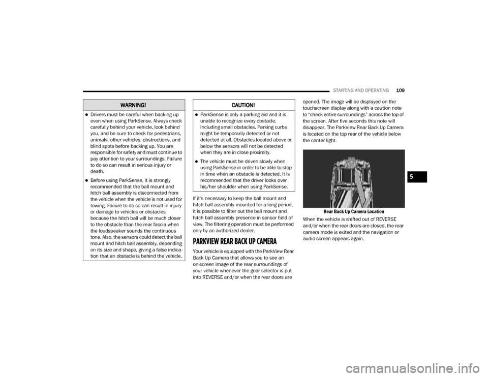
disappear. The ParkView Rear Back Up Camera
is located on the top rear of the vehicle below
the center light.
Rear Back Up Camera Location
When the vehicle is shifted out of REVERSE
and/or when the rear doors are closed, the rear
camera mode is exited and the navigation or
audio screen appears again.
WARNING!
Drivers must be careful when backing up
even when using ParkSense. Always check
carefully behind your vehicle, look behind
you, and be sure to check for pedestrians,
animals, other vehicles, obstructions, and
blind spots before backing up. You are
responsible for safety and must continue to
pay attention to your surroundings. Failure
to do so can result in serious injury or
death.
Before using ParkSense, it is strongly
recommended that the ball mount and
hitch ball assembly is disconnected from
the vehicle when the vehicle is not used for
towing. Failure to do so can result in injury
or damage to vehicles or obstacles
because the hitch ball will be much closer
to the obstacle than the rear fascia when
the loudspeaker sounds the continuous
tone. Also, the sensors could detect the ball
mount and hitch ball assembly, depending
on its size and shape, giving a false indica -
tion that an obstacle is behind the vehicle.
CAUTION!
ParkSense is only a parking aid and it is
unable to recognize every obstacle,
including small obstacles. Parking curbs
might be temporarily detected or not
detected at all. Obstacles located above or
below the sensors will not be detected
when they are in close proximity.
The vehicle must be driven slowly when
using ParkSense in order to be able to stop
in time when an obstacle is detected. It is
recommended that the driver looks over
his/her shoulder when using ParkSense.
5
20_VF_OM_EN_US_t.book Page 109
Page 114 of 264
112STARTING AND OPERATING
VEHICLE LOADING
As required by National Highway Traffic Safety
Administration regulations, your vehicle has a
certification label affixed to the driver's side
door or B-Pillar.
If seats are removed for carrying cargo, do not
exceed the specified GVWR and GAWR.
Vehicle Certification Label
Your vehicle has a Vehicle Certification Label
affixed to the drivers side B-Pillar or the rear of
the driver’s door.
The label contains the following information:
Name of manufacturer
Month and year of manufacture
Gross Vehicle Weight Rating (GVWR)
Gross Axle Weight Rating (GAWR) front
Gross Axle Weight Rating (GAWR) rear
Vehicle Identification Number (VIN)
Type of vehicle
Month, Day, and Hour of manufacture (MDH)
The bar code allows a computer scanner to read
the VIN.
Gross Vehicle Weight Rating (GVWR)
The Gross Vehicle Weight Rating (GVWR) is the
total allowable weight of your vehicle. This
includes driver, passengers, and cargo. The
total load must be limited so that you do not
exceed the GVWR.
Gross Axle Weight Rating (GAWR)
The Gross Axle Weight Rating (GAWR) is the
maximum capacity of the front and rear axles.
Distribute the load over the front and rear axles
evenly. Make sure that you do not exceed either
front or rear GAWR.
Tire Size
The tire size on the Vehicle Certification Label
represents the actual tire size on your vehicle.
Replacement tires must be equal to the load
capacity of this tire size.
Rim Size
This is the rim size that is appropriate for the tire
size listed.
Inflation Pressure
This is the cold tire inflation pressure for your
vehicle for all loading conditions up to full Gross
Axle Weight Rating (GAWR).
Curb Weight
The curb weight of a vehicle is defined as the
total weight of the vehicle with all fluids,
including vehicle fuel, at full capacity condi -
tions, and with no occupants or cargo loaded
into the vehicle. The front and rear curb weight
values are determined by weighing your vehicle
on a commercial scale before any occupants or
cargo are added.
Overloading
The load carrying components (axle, springs,
tires, wheels, etc.) of your vehicle will provide
satisfactory service as long as you do not
exceed the Gross Vehicle Weight Rating (GVWR)
and the front and rear Gross Axle Weight Rating
(GAWR).
WARNING!
Because the front wheels steer the vehicle, it
is important that you do not exceed the
maximum front or rear GAWR. A dangerous
driving condition can result if either rating is
exceeded. You could lose control of the
vehicle and have a collision.
20_VF_OM_EN_US_t.book Page 112
Page 119 of 264

STARTING AND OPERATING117
Towing Requirements — Tires
Do not attempt to tow a trailer while using a
compact spare tire.
Do not drive more than 50 mph (80 km/h) when towing while using a full size spare tire.
Proper tire inflation pressures are essential
to the safe and satisfactory operation of your
vehicle. Refer to “Tires” in “Servicing And
Maintenance” for proper tire inflation proce -
dures.
Check the trailer tires for proper tire inflation
pressures before trailer usage.
Check for signs of tire wear or visible tire
damage before towing a trailer. Refer to
“Tires” in “Servicing And Maintenance” for
the proper inspection procedure.
When replacing tires, refer to “Tires” in
“Servicing And Maintenance” for the proper
tire replacement procedures. Replacing tires
with a higher load carrying capacity will not
increase the vehicle's GVWR and GAWR
limits.
Towing Requirements — Trailer Brakes
Do not interconnect the hydraulic brake
system or vacuum system of your vehicle
with that of the trailer. This could cause inad -
equate braking and possible personal injury.
An electronically actuated trailer brake
controller is required when towing a trailer
with electronically actuated brakes. When
towing a trailer equipped with a hydraulic
surge actuated brake system, an electronic
brake controller is not required.
Trailer brakes are recommended for trailers
over 1,000 lbs (453 kg) and may be required
for any trailer, for example trailers in excess
of 2,000 lbs (907 kg). Trailer brake require -
ments vary by local law, consult local legal
requirements where the trailer is to be towed
for trailer brake requirements.
WARNING!
Do not connect trailer brakes to your
vehicle's hydraulic brake lines. It can over -
load your brake system and cause it to fail.
You might not have brakes when you need
them and could have an accident.
Towing any trailer will increase your stop -
ping distance. When towing, you should
allow for additional space between your
vehicle and the vehicle in front of you.
Failure to do so could result in an accident.
CAUTION!
If the trailer weighs more than 1,000 lbs
(453 kg) loaded, it should have its own
brakes and they should be of adequate
capacity. Failure to do this could lead to
accelerated brake lining wear, higher brake
pedal effort, and longer stopping distances.
5
20_VF_OM_EN_US_t.book Page 117
Page 170 of 264
168SERVICING AND MAINTENANCE
Fluid Level Check
The fluid level is preset at the factory and does
not require adjustment under normal operating
conditions. Routine fluid level checks are not
required, therefore the transmission filler tube
is capped and no dipstick is provided. Your
authorized dealer can check your transmission
fluid level using a special service dipstick. If you
notice fluid leakage or transmission malfunc-
tion, visit your authorized dealer immediately to
have the transmission fluid level checked. Oper -
ating the vehicle with an improper fluid level can
cause severe transmission damage.
Fluid And Filter Changes
Refer to the “Maintenance Plan” in this section
for the proper maintenance intervals.
In addition, change the fluid and filter if the fluid
becomes contaminated (with water, etc.), or if
the transmission is disassembled for any
reason.
RAISING THE VEHICLE
In the case where it is necessary to raise the
vehicle, go to an authorized dealer or service
station.
TIRES
Tire Safety Information
Tire safety information will cover aspects of the
following information: Tire Markings, Tire Identi -
fication Numbers, Tire Terminology and Defini -
tions, Tire Pressures, and Tire Loading.
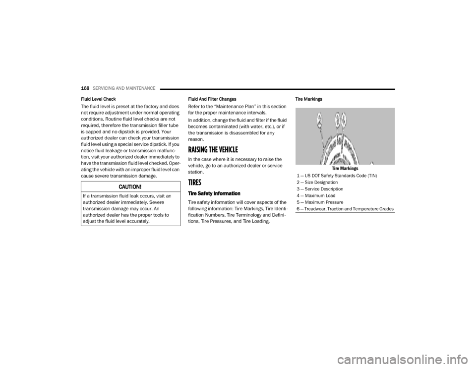
Tire Markings
Tire Markings
CAUTION!
If a transmission fluid leak occurs, visit an
authorized dealer immediately. Severe
transmission damage may occur. An
authorized dealer has the proper tools to
adjust the fluid level accurately.
1 — US DOT Safety Standards Code (TIN)
2 — Size Designation
3 — Service Description
4 — Maximum Load
5 — Maximum Pressure
6 — Treadwear, Traction and Temperature Grades
20_VF_OM_EN_US_t.book Page 168