heater RAM PROMASTER 2021 Owners Manual
[x] Cancel search | Manufacturer: RAM, Model Year: 2021, Model line: PROMASTER, Model: RAM PROMASTER 2021Pages: 288, PDF Size: 15.22 MB
Page 5 of 288

3
GETTING TO KNOW YOUR
INSTRUMENT PANEL
INSTRUMENT CLUSTER........................................42Instrument Cluster Descriptions ................. 43
INSTRUMENT CLUSTER DISPLAY .......................44
Location And Controls ................................. 44
Change Engine Oil — If Equipped................ 45
Display Setup Menu .................................... 46
Values Displayed ......................................... 46
Personal Settings
(Customer-Programmable Features) .......... 47
TRIP COMPUTER ...................................................47
Trip Button.................................................... 47
Trip Functions .............................................. 48
WARNING LIGHTS AND MESSAGES ..................48
Red Warning Lights...................................... 48
Yellow Warning Lights ................................. 50
Yellow Indicator Lights................................. 53
Green Indicator Lights ................................. 54
Blue Indicator Lights .................................... 54
ONBOARD DIAGNOSTIC SYSTEM — OBD II ......55
Onboard Diagnostic System (OBD II)
Cybersecurity................................................ 55
EMISSIONS INSPECTION AND MAINTENANCE
PROGRAMS ...........................................................56
STARTING AND OPERATING
STARTING THE ENGINE ...................................... 57
Automatic Transmission.............................. 57
Normal Starting............................................ 57
Cold Weather Operation
(Below –22°F Or −30°C) ........................... 57 If Engine Fails To Start ................................ 57
After Starting ................................................ 58
ENGINE BLOCK HEATER — IF EQUIPPED ......... 58
ENGINE BREAK-IN RECOMMENDATIONS ........ 58
PARKING BRAKE ................................................. 59
AUTOMATIC TRANSMISSION ............................. 60 Key Ignition Park Interlock .......................... 60
Brake/Transmission Shift Interlock
System ......................................................... 60 Six-Speed Automatic Transmission ............ 61
POWER STEERING .............................................. 66
Power Steering Fluid Check ....................... 67
CRUISE CONTROL — IF EQUIPPED .................... 67
To Activate.................................................... 68
To Set A Desired Speed............................... 68
To Vary The Speed Setting .......................... 68
To Accelerate For Passing ........................... 69
To Resume Speed ....................................... 69
To Deactivate ............................................... 69
PARKSENSE REAR PARK ASSIST —
IF EQUIPPED ......................................................... 69
ParkSense Rear Park Assist Sensors ......... 70
ParkSense Rear Park Assist Alerts ............. 70 ParkSense Rear Park Assist Failure
Indications.................................................... 72 Cleaning The ParkSense System................ 72
ParkSense Rear Park Assist System
Usage Precautions ...................................... 72
PARKVIEW REAR BACK UP CAMERA ...............73
REFUELING THE VEHICLE ....................................75
Loose Fuel Filler Cap Message................... 76
VEHICLE LOADING ................................................76
Vehicle Certification Label .......................... 76
Gross Vehicle Weight Rating (GVWR) ......... 76
Gross Axle Weight Rating (GAWR) ............. 76
Tire Size ........................................................ 77
Rim Size ....................................................... 77
Inflation Pressure ........................................ 77
Curb Weight ................................................. 77
Overloading .................................................. 77
Loading ........................................................ 77
TRAILER TOWING .................................................78
Common Towing Definitions ....................... 78
Trailer Hitch Classification .......................... 80
Trailer Towing Weights
(Maximum Trailer Weight Ratings) ............ 81 Trailer And Tongue Weight ......................... 81
Towing Requirements ................................ 81
Towing Tips ................................................. 84
RECREATIONAL TOWING
(BEHIND MOTORHOME) ......................................85
Towing This Vehicle Behind Another
Vehicle .......................................................... 85 Recreational Towing .................................... 85
21_VF_OM_EN_USC_t.book Page 3
Page 9 of 288

7
SYMBOLS KEY
WARNINGS AND CAUTIONS
This Owner’s Manual contains WARNINGS against operating procedures
that could result in a collision, bodily injury, and/or death. It also contains
CAUTIONS against procedures that could result in damage to your vehicle. If you do not read this entire Owner’s Manual, you may miss important
information. Observe all Warnings and Cautions.
VAN CONVERSIONS/CAMPERS
The New Vehicle Limited Warranty does not apply to body modifications or
special equipment installed by van conversion/camper manufacturers/
body builders. US residents refer to the Warranty Information, Section
2.1.C. Canadian residents refer to the “What Is Not Covered” section of
the Warranty Information. Such equipment includes video monitors, DVD/
Blu-Ray™, heaters, stoves, refrigerators, etc. For warranty coverage and
service on these items, contact the applicable manufacturer.
Operating instructions for the special equipment installed by the
conversion/camper manufacturer should also be supplied with your
vehicle. For any additional instructions, please contact your conversion/
camper manufacturer.
To obtain dimensional and technical specifications for your vehicle, refer
to the Body Builder’s Guide at https://www.ramtrucks.com/
ram-commercial/body-builders-guide.html.
VEHICLE MODIFICATIONS/ALTERATIONS
WARNING!
Indicates a potentially hazardous situation,
which if not avoided, could result in death or
serious injury.
CAUTION! An unsafe practice which may result in personal
injury or damage to the vehicle.
NOTE: A suggestion which will improve installation,
operation, and reliability. If not followed, may
result in damage.
TIP: General ideas/solutions/suggestions on easier
use of the product or functionality.
PAGE REFERENCE
ARROW
Follow this reference for additional information
on a particular feature.
FOOTNOTE Supplementary and relevant information
pertaining to the topic.
WARNING!
Any modifications or alterations to this vehicle could seriously affect its
roadworthiness and safety and may lead to a collision resulting in
serious injury or death.
1
21_VF_OM_EN_USC_t.book Page 7
Page 21 of 288

GETTING TO KNOW YOUR VEHICLE19
If the driver or the passenger seats are not locked
in the facing forward position before the first
vehicle movement, shifting out of park is not
allowed until the seats are both locked in the
facing forward position. When the seats are not in
the right position and the first vehicle movement
after ignition START is attempted, a chime and a
message will appear in the instrument cluster
display. Rotate and lock the swivel seats in the
correct position before trying again.
If the driver or the passenger seats are not
locked in the facing forward position during
movement of the vehicle, a message will appear
in the instrument cluster display and an
intermittent chime will sound until key-off or
until the swivel seats are locked in the facing
forward position. Stop and move the swivel
seats in the correct position before proceeding.
If a fault is present in the system and it is not
possible to check the correct position of the
swivel seats, a message and the generic
warning light appears in the instrument cluster
display to inform about the failure. In these
conditions, check the status of the swivel seats
and do not drive the vehicle until the swivel
seats are locked in the facing forward position.HEATED SEATS — IF EQUIPPED
On some models, the front driver and
passenger seats may be equipped with heaters
in both the seat cushions and seatbacks. The
controls for the front heated seats are located
on the lower outboard side of the seat.
Heated Seat Switch
Push the switch once to turn on the heated
seats. Push the switch a second time to shut the
heating elements off. NOTE:
Once a heat setting is selected, heat will be felt
within two to five minutes.
WARNING!
Persons who are unable to feel pain to the
skin because of advanced age, chronic
illness, diabetes, spinal cord injury, medica
-
tion, alcohol use, exhaustion or other phys -
ical condition must exercise care when
using the seat heater. It may cause burns
even at low temperatures, especially if
used for long periods of time.
Do not place anything on the seat or seat -
back that insulates against heat, such as a
blanket or cushion. This may cause the seat
heater to overheat. Sitting in a seat that has
been overheated could cause serious
burns due to the increased surface
temperature of the seat.
2
21_VF_OM_EN_USC_t.book Page 19
Page 36 of 288

34GETTING TO KNOW YOUR VEHICLE
ADDITIONAL REAR CLIMATE CONTROL —
I
F EQUIPPED
These switches, mounted on the instrument
panel to the left of the steering column, activate
the additional rear heating/air conditioning
system.
NOTE:
These switches must be enabled for operation
by the Upfitter.
Additional Rear Climate Controls Switches
Rear Blower Control
Push this button to turn on the rear
climate controls. An indicator light will
turn on when the rear climate control
is on.
Rear Temperature Control
Rear Passenger Temperature Up
Button To change the temperature in
the rear of the vehicle, push
temperature control up button to
raise the temperature.
Rear Passenger Temperature Down
Button To change the temperature in
the rear of the vehicle, push
temperature control down button to
lower the temperature.
Rear MODE Button
Push this button to change the air
distribution mode for the rear
passengers.
OPERATING TIPS
NOTE:
Refer to the chart at the end of this section for
suggested control settings for various weather
conditions.
Summer Operation
The engine cooling system must be protected
with a high-quality antifreeze coolant to provide
proper corrosion protection and to protect
against engine overheating. A solution of 50%
OAT (Organic Additive Technology) coolant that
meets the requirements of FCA Material
Standard MS.90032 and 50% water is
recommended Ú page 268.
Winter Operation
To ensure the best possible heater and
defroster performance, make sure the engine
cooling system is functioning properly and the
proper amount, type, and concentration of
coolant is used. Use of the air Recirculation
mode during Winter months is not
recommended because it may cause
window fogging.
21_VF_OM_EN_USC_t.book Page 34
Page 59 of 288

57
(Continued)
STARTING AND OPERATING
STARTING THE ENGINE
Before starting your vehicle, adjust your seat,
adjust both inside and outside mirrors, and
fasten your seat belts.
AUTOMATIC TRANSMISSION
The gear selector must be in the PARK or
NEUTRAL position before you can start the
engine. Press the brake pedal before shifting to
any driving gear.
NOTE:
You must press the brake pedal before shifting
out of PARK.
NORMAL STARTING
Turn the ignition switch to the AVV (START)
position and release it when the engine starts.
If the engine fails to start within 10 seconds,
turn the ignition switch to the STOP (OFF/LOCK)
position, wait 10 to 15 seconds, then repeat the
“Normal Starting” procedure.
COLD WEATHER OPERATION (BELOW
–22°F O
R −30°C)
To ensure reliable starting at these
temperatures, use of an externally powered
electric engine block heater (available from an
authorized dealer) is recommended.
IF ENGINE FAILS TO START
If the engine fails to start after you have
followed the “Normal Starting” procedure, it
may be flooded. Push the accelerator pedal all
the way to the floor and hold it there. Crank the
engine for no more than 15 seconds. This
should clear any excess fuel in case the engine
is flooded. Leave the ignition key in the RUN
position, release the accelerator pedal and
repeat the “Normal Starting” procedure.
WARNING!
Never leave children alone in a vehicle, or
with access to an unlocked vehicle.
Allowing children to be in a vehicle unat -
tended is dangerous for a number of
reasons. A child or others could be seriously
or fatally injured. Children should be
warned not to touch the parking brake,
brake pedal or the transmission gear
selector.
Do not leave the key fob in or near the
vehicle (or in a location accessible to chil -
dren). A child could operate power
windows, other controls, or move the
vehicle.
WARNING!
Never pour fuel or other flammable liquid
into the throttle body air inlet opening in an
attempt to start the vehicle. This could
result in flash fire causing serious personal
injury.
Do not attempt to push or tow your vehicle
to get it started. Vehicles equipped with an
automatic transmission cannot be started
this way. Unburned fuel could enter the
catalytic converter and once the engine has
started, ignite and damage the converter
and vehicle.
4
21_VF_OM_EN_USC_t.book Page 57
Page 60 of 288

58STARTING AND OPERATING
AFTER STARTING
The idle speed is controlled automatically, and
it will decrease as the engine warms up.
ENGINE BLOCK HEATER — IF EQUIPPED
The engine block heater warms the engine, and
permits quicker starts in cold weather. Connect
the cord to a standard 110-115 Volt AC
electrical outlet with a grounded, three-wire
extension cord. The engine block heater must be plugged in at
least one hour to have an adequate warming
effect on the engine.
ENGINE BREAK-IN RECOMMENDATIONS
A long break-in period is not required for the
engine and drivetrain (transmission and axle) in
your vehicle.
Drive moderately during the first 300 miles
(500 km). After the initial 60 miles (100 km),
speeds up to 50 or 55 mph (80 or 90 km/h) are
desirable.
While cruising, brief full-throttle acceleration
within the limits of local traffic laws contributes
to a good break-in. Wide-open throttle
acceleration in low gear can be detrimental and
should be avoided.
The engine oil installed in the engine at the
factory is a high-quality energy conserving type
lubricant. Oil changes should be consistent with
anticipated climate conditions under which
vehicle operations will occur. For the
recommended viscosity and quality grades see
Ú
page 268.
NOTE:
A new engine may consume some oil during its
first few thousand miles (kilometers) of opera -
tion. This should be considered a normal part of
the break-in and not interpreted as a problem.
Please check your oil level with the engine oil
indicator often during the break-in period. Add
oil as required.
If the vehicle has a discharged battery,
booster cables may be used to obtain a
start from a booster battery or the battery in
another vehicle. This type of start can be
dangerous if done improperly Úpage 203.
CAUTION!
To prevent damage to the starter, do not
continuously crank the engine for more than
25 seconds at a time. Wait 60 seconds
before trying again.
WARNING! (Continued)
WARNING!
Remember to disconnect the engine block
heater cord before driving. Damage to the
110-115 Volt electrical cord could cause
electrocution.
CAUTION!
Never use Non-Detergent Oil or Straight
Mineral Oil in the engine or damage may
result.
21_VF_OM_EN_USC_t.book Page 58
Page 206 of 288

204IN CASE OF EMERGENCY
See below steps to prepare for jump starting:
1. Apply the parking brake, shift the
automatic transmission into PARK (P) and
turn the ignition to the OFF position.
2. Turn off the heater, radio, and all electrical accessories.
3. Pull upward and remove the protective cover over the remote positive (+) battery
post.
4. If using another vehicle to jump start the battery, park the vehicle within the jumper
cables reach, apply the parking brake and
make sure the ignition is OFF.
JUMP STARTING PROCEDURE
Connecting The Jumper Cables
Jumper Cable Connections
1. Connect the positive
(+) end of the jumper
cable to the remote positive (+)
post of the
discharged vehicle.
NOTE:
The remote positive (+) post is located in the
engine compartment on the driver's side under
the cover of the Front Power Distribution Center.
Batteries contain sulfuric acid that can
burn your skin or eyes and generate
hydrogen gas which is flammable and
explosive. Keep open flames or sparks
away from the battery.
WARNING! (Continued)WARNING!
Do not allow vehicles to touch each other as
this could establish a ground connection and
personal injury could result.
WARNING!
Failure to follow this jump starting procedure
could result in personal injury or property
damage due to battery explosion.
CAUTION!
Failure to follow these procedures could
result in damage to the charging system of
the booster vehicle or the discharged vehicle.
21_VF_OM_EN_USC_t.book Page 204
Page 208 of 288

206IN CASE OF EMERGENCY
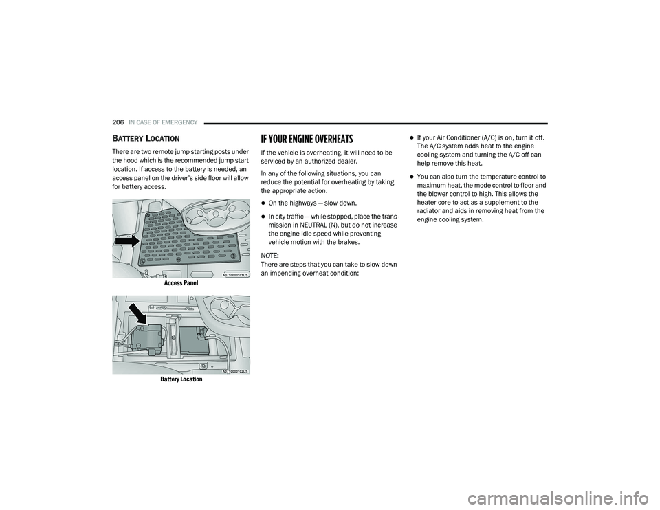
BATTERY LOCATION
There are two remote jump starting posts under
the hood which is the recommended jump start
location. If access to the battery is needed, an
access panel on the driver’s side floor will allow
for battery access.
Access Panel
Battery Location
IF YOUR ENGINE OVERHEATS
If the vehicle is overheating, it will need to be
serviced by an authorized dealer.
In any of the following situations, you can
reduce the potential for overheating by taking
the appropriate action.
On the highways — slow down.
In city traffic — while stopped, place the trans -
mission in NEUTRAL (N), but do not increase
the engine idle speed while preventing
vehicle motion with the brakes.
NOTE:
There are steps that you can take to slow down
an impending overheat condition:
If your Air Conditioner (A/C) is on, turn it off.
The A/C system adds heat to the engine
cooling system and turning the A/C off can
help remove this heat.
You can also turn the temperature control to
maximum heat, the mode control to floor and
the blower control to high. This allows the
heater core to act as a supplement to the
radiator and aids in removing heat from the
engine cooling system.
21_VF_OM_EN_USC_t.book Page 206
Page 236 of 288

234SERVICING AND MAINTENANCE
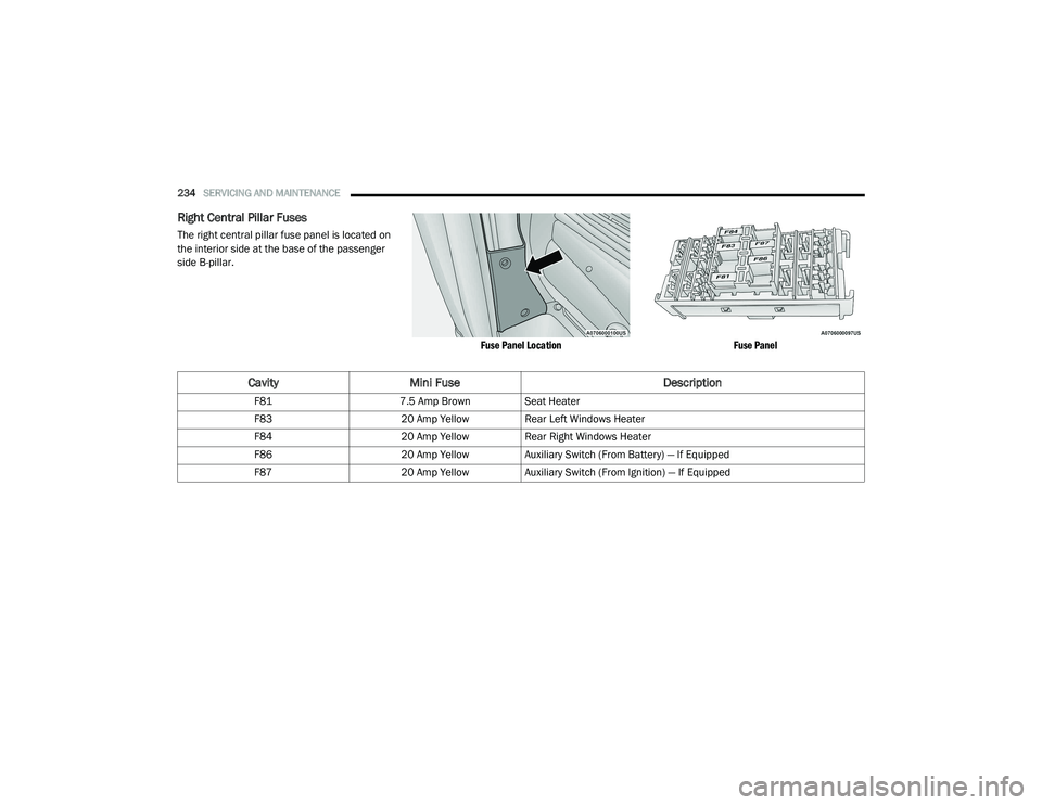
Right Central Pillar Fuses
The right central pillar fuse panel is located on
the interior side at the base of the passenger
side B-pillar.
Fuse Panel LocationFuse Panel
CavityMini Fuse Description
F817.5 Amp Brown Seat Heater
F83 20 Amp YellowRear Left Windows Heater
F84 20 Amp YellowRear Right Windows Heater
F86 20 Amp YellowAuxiliary Switch (From Battery) — If Equipped
F87 20 Amp YellowAuxiliary Switch (From Ignition) — If Equipped
21_VF_OM_EN_USC_t.book Page 234
Page 279 of 288

277
Emergency, In Case Of Freeing Vehicle When Stuck
...................... 208Jacking...................................................... 190Jump Starting............................................ 203Emission Control System Maintenance........... 56Engine........................................................... 215Air Cleaner................................................. 219Block Heater............................................... 58Break-In Recommendations........................ 58Checking Oil Level..................................... 216Compartment............................................ 215Compartment Identification...................... 215Coolant (Antifreeze)......................... 223, 268Cooling...................................................... 223Exhaust Gas Caution................................. 189Fails To Start............................................... 57Flooded, Starting......................................... 57Fuel Requirements.......................... 265, 268Jump Starting............................................ 203Oil.................................................... 218, 268Oil Filler Cap.............................................. 215Oil Filter..................................................... 219Oil Selection.................................... 218, 268Oil Synthetic.............................................. 218Overheating............................................... 206Starting....................................................... 57Enhanced Accident Response Feature..........210Entry System, Illuminated................................ 30
Ethanol......................................................... 266Exhaust Gas Cautions................................... 189Exhaust System................................... 189, 221Exterior Lights.........................................26, 188
F
FiltersAir Cleaner
................................................ 219Air Conditioning..................................35, 220Engine Oil........................................ 219, 268Engine Oil Disposal................................... 218FlashersHazard Warning........................................ 190Turn Signals.......................................54, 188Flat Tire Changing................................ 240, 253Flat Tire Stowage................................. 240, 253Flooded Engine Starting................................... 57Fluid Capacities............................................ 268Fluid Leaks................................................... 189Fluid Level ChecksAutomatic Transmission........................... 227Brake........................................................ 226Cooling System......................................... 223Engine Oil................................................. 216Power Steering............................................ 67Fog Lights........................................................ 27Fold-Flat Seats................................................. 15Forward Collision Warning............................ 159
Four-Way Hazard Flasher.............................. 190Freeing A Stuck Vehicle................................. 208Fuel............................................................... 265Additives................................................... 266Clean Air................................................... 266Ethanol..................................................... 266Filler Cap (Gas Cap).....................................75Gasoline................................................... 265Materials Added....................................... 266Methanol.................................................. 266Octane Rating.................................. 265, 268Requirements.................................. 265, 268Tank Capacity........................................... 268Fuses............................................................ 228
G
Gas Cap (Fuel Filler Cap)...........................75, 76Gasoline, Clean Air........................................ 266Gasoline, Reformulated................................ 266Gear Ranges....................................................62Gear Selector Override.................................. 207Glass Cleaning.............................................. 263Gross Axle Weight Rating.......................... 76, 78Gross Vehicle Weight Rating.....................76, 78GuideBody Builders................................................. 7GVWR...............................................................7611
21_VF_OM_EN_USC_t.book Page 277