sensor RAM PROMASTER 2021 Owners Manual
[x] Cancel search | Manufacturer: RAM, Model Year: 2021, Model line: PROMASTER, Model: RAM PROMASTER 2021Pages: 288, PDF Size: 15.22 MB
Page 5 of 288
3
GETTING TO KNOW YOUR
INSTRUMENT PANEL
INSTRUMENT CLUSTER........................................42Instrument Cluster Descriptions ................. 43
INSTRUMENT CLUSTER DISPLAY .......................44
Location And Controls ................................. 44
Change Engine Oil — If Equipped................ 45
Display Setup Menu .................................... 46
Values Displayed ......................................... 46
Personal Settings
(Customer-Programmable Features) .......... 47
TRIP COMPUTER ...................................................47
Trip Button.................................................... 47
Trip Functions .............................................. 48
WARNING LIGHTS AND MESSAGES ..................48
Red Warning Lights...................................... 48
Yellow Warning Lights ................................. 50
Yellow Indicator Lights................................. 53
Green Indicator Lights ................................. 54
Blue Indicator Lights .................................... 54
ONBOARD DIAGNOSTIC SYSTEM — OBD II ......55
Onboard Diagnostic System (OBD II)
Cybersecurity................................................ 55
EMISSIONS INSPECTION AND MAINTENANCE
PROGRAMS ...........................................................56
STARTING AND OPERATING
STARTING THE ENGINE ...................................... 57
Automatic Transmission.............................. 57
Normal Starting............................................ 57
Cold Weather Operation
(Below –22°F Or −30°C) ........................... 57 If Engine Fails To Start ................................ 57
After Starting ................................................ 58
ENGINE BLOCK HEATER — IF EQUIPPED ......... 58
ENGINE BREAK-IN RECOMMENDATIONS ........ 58
PARKING BRAKE ................................................. 59
AUTOMATIC TRANSMISSION ............................. 60 Key Ignition Park Interlock .......................... 60
Brake/Transmission Shift Interlock
System ......................................................... 60 Six-Speed Automatic Transmission ............ 61
POWER STEERING .............................................. 66
Power Steering Fluid Check ....................... 67
CRUISE CONTROL — IF EQUIPPED .................... 67
To Activate.................................................... 68
To Set A Desired Speed............................... 68
To Vary The Speed Setting .......................... 68
To Accelerate For Passing ........................... 69
To Resume Speed ....................................... 69
To Deactivate ............................................... 69
PARKSENSE REAR PARK ASSIST —
IF EQUIPPED ......................................................... 69
ParkSense Rear Park Assist Sensors ......... 70
ParkSense Rear Park Assist Alerts ............. 70 ParkSense Rear Park Assist Failure
Indications.................................................... 72 Cleaning The ParkSense System................ 72
ParkSense Rear Park Assist System
Usage Precautions ...................................... 72
PARKVIEW REAR BACK UP CAMERA ...............73
REFUELING THE VEHICLE ....................................75
Loose Fuel Filler Cap Message................... 76
VEHICLE LOADING ................................................76
Vehicle Certification Label .......................... 76
Gross Vehicle Weight Rating (GVWR) ......... 76
Gross Axle Weight Rating (GAWR) ............. 76
Tire Size ........................................................ 77
Rim Size ....................................................... 77
Inflation Pressure ........................................ 77
Curb Weight ................................................. 77
Overloading .................................................. 77
Loading ........................................................ 77
TRAILER TOWING .................................................78
Common Towing Definitions ....................... 78
Trailer Hitch Classification .......................... 80
Trailer Towing Weights
(Maximum Trailer Weight Ratings) ............ 81 Trailer And Tongue Weight ......................... 81
Towing Requirements ................................ 81
Towing Tips ................................................. 84
RECREATIONAL TOWING
(BEHIND MOTORHOME) ......................................85
Towing This Vehicle Behind Another
Vehicle .......................................................... 85 Recreational Towing .................................... 85
21_VF_OM_EN_USC_t.book Page 3
Page 54 of 288
52GETTING TO KNOW YOUR INSTRUMENT PANEL
Electronic Stability Control (ESC) Warning
Light
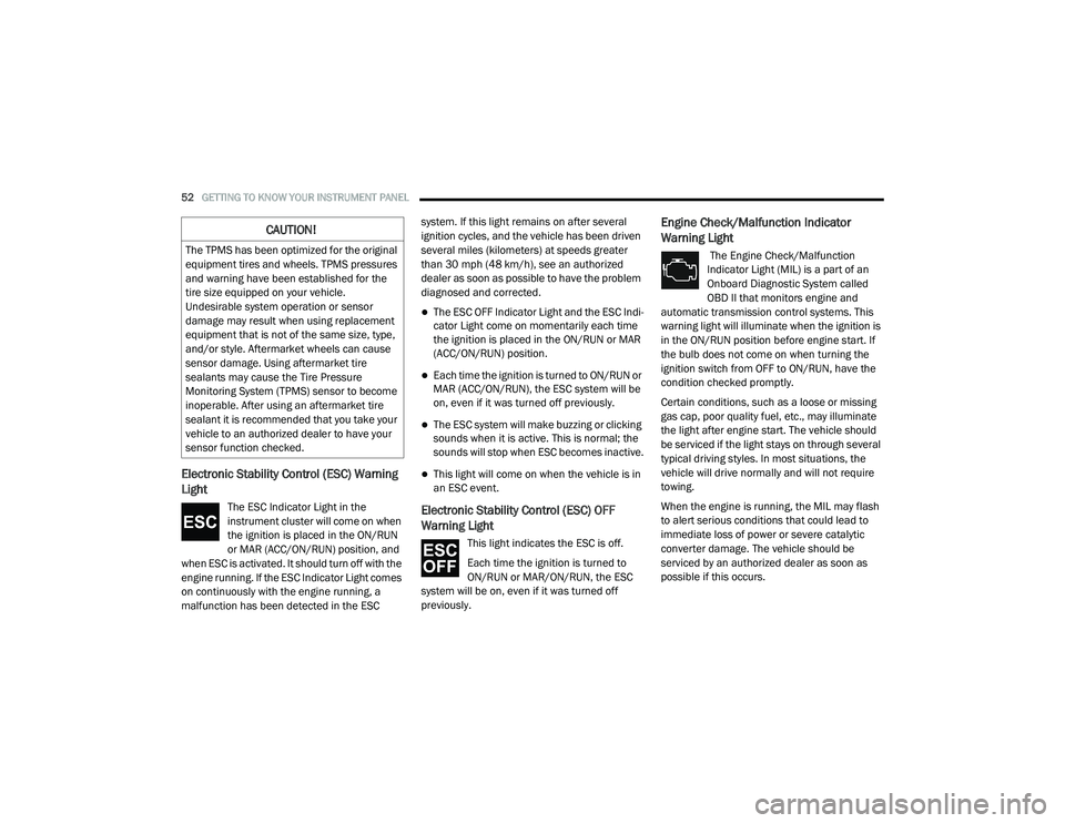
The ESC Indicator Light in the
instrument cluster will come on when
the ignition is placed in the ON/RUN
or MAR (ACC/ON/RUN) position, and
when ESC is activated. It should turn off with the
engine running. If the ESC Indicator Light comes
on continuously with the engine running, a
malfunction has been detected in the ESC system. If this light remains on after several
ignition cycles, and the vehicle has been driven
several miles (kilometers) at speeds greater
than 30 mph (48 km/h), see an authorized
dealer as soon as possible to have the problem
diagnosed and corrected.
The ESC OFF Indicator Light and the ESC Indi
-
cator Light come on momentarily each time
the ignition is placed in the ON/RUN or MAR
(ACC/ON/RUN) position.
Each time the ignition is turned to ON/RUN or
MAR (ACC/ON/RUN), the ESC system will be
on, even if it was turned off previously.
The ESC system will make buzzing or clicking
sounds when it is active. This is normal; the
sounds will stop when ESC becomes inactive.
This light will come on when the vehicle is in
an ESC event.
Electronic Stability Control (ESC) OFF
Warning Light
This light indicates the ESC is off.
Each time the ignition is turned to
ON/RUN or MAR/ON/RUN, the ESC
system will be on, even if it was turned off
previously.
Engine Check/Malfunction Indicator
Warning Light
The Engine Check/Malfunction
Indicator Light (MIL) is a part of an
Onboard Diagnostic System called
OBD II that monitors engine and
automatic transmission control systems. This
warning light will illuminate when the ignition is
in the ON/RUN position before engine start. If
the bulb does not come on when turning the
ignition switch from OFF to ON/RUN, have the
condition checked promptly.
Certain conditions, such as a loose or missing
gas cap, poor quality fuel, etc., may illuminate
the light after engine start. The vehicle should
be serviced if the light stays on through several
typical driving styles. In most situations, the
vehicle will drive normally and will not require
towing.
When the engine is running, the MIL may flash
to alert serious conditions that could lead to
immediate loss of power or severe catalytic
converter damage. The vehicle should be
serviced by an authorized dealer as soon as
possible if this occurs.
CAUTION!
The TPMS has been optimized for the original
equipment tires and wheels. TPMS pressures
and warning have been established for the
tire size equipped on your vehicle.
Undesirable system operation or sensor
damage may result when using replacement
equipment that is not of the same size, type,
and/or style. Aftermarket wheels can cause
sensor damage. Using aftermarket tire
sealants may cause the Tire Pressure
Monitoring System (TPMS) sensor to become
inoperable. After using an aftermarket tire
sealant it is recommended that you take your
vehicle to an authorized dealer to have your
sensor function checked.
21_VF_OM_EN_USC_t.book Page 52
Page 55 of 288
GETTING TO KNOW YOUR INSTRUMENT PANEL53
Anti-Lock Brake System (ABS) Warning
Light
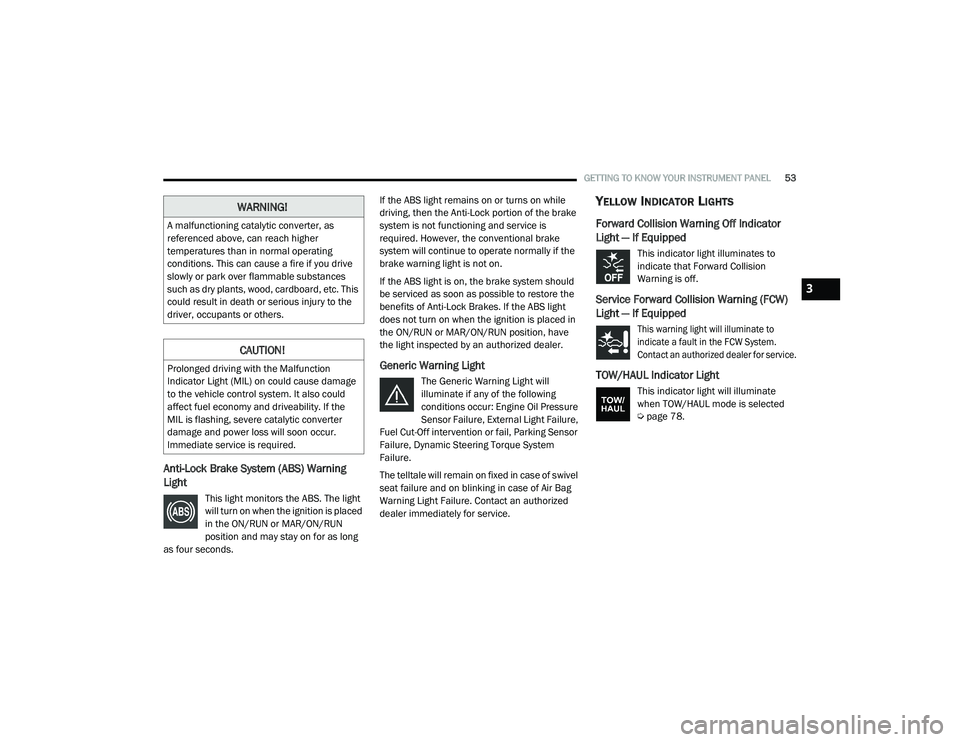
This light monitors the ABS. The light
will turn on when the ignition is placed
in the ON/RUN or MAR/ON/RUN
position and may stay on for as long
as four seconds. If the ABS light remains on or turns on while
driving, then the Anti-Lock portion of the brake
system is not functioning and service is
required. However, the conventional brake
system will continue to operate normally if the
brake warning light is not on.
If the ABS light is on, the brake system should
be serviced as soon as possible to restore the
benefits of Anti-Lock Brakes. If the ABS light
does not turn on when the ignition is placed in
the ON/RUN or MAR/ON/RUN position, have
the light inspected by an authorized dealer.
Generic Warning Light
The Generic Warning Light will
illuminate if any of the following
conditions occur: Engine Oil Pressure
Sensor Failure, External Light Failure,
Fuel Cut-Off intervention or fail, Parking Sensor
Failure, Dynamic Steering Torque System
Failure.
The telltale will remain on fixed in case of swivel
seat failure and on blinking in case of Air Bag
Warning Light Failure. Contact an authorized
dealer immediately for service.
YELLOW INDICATOR LIGHTS
Forward Collision Warning Off Indicator
Light — If Equipped
This indicator light illuminates to
indicate that Forward Collision
Warning is off.
Service Forward Collision Warning (FCW)
Light — If Equipped
This warning light will illuminate to
indicate a fault in the FCW System.
Contact an authorized dealer for service.
TOW/HAUL Indicator Light
This indicator light will illuminate
when TOW/HAUL mode is selected
Ú page 78.
WARNING!
A malfunctioning catalytic converter, as
referenced above, can reach higher
temperatures than in normal operating
conditions. This can cause a fire if you drive
slowly or park over flammable substances
such as dry plants, wood, cardboard, etc. This
could result in death or serious injury to the
driver, occupants or others.
CAUTION!
Prolonged driving with the Malfunction
Indicator Light (MIL) on could cause damage
to the vehicle control system. It also could
affect fuel economy and driveability. If the
MIL is flashing, severe catalytic converter
damage and power loss will soon occur.
Immediate service is required.
3
21_VF_OM_EN_USC_t.book Page 53
Page 72 of 288

70STARTING AND OPERATING
PARKSENSE REAR PARK ASSIST
S
ENSORS
The four ParkSense Rear Park Assist sensors,
located in the rear fascia/bumper, monitor the
area behind the vehicle that is within the
sensors’ field of view. The sensors can detect
obstacles, in the horizontal direction, from
approximately 12 inches (30 cm) up to
55 inches (140 cm) from the center of the rear
fascia/bumper and up to 24 inches (60 cm)
from the corners of the rear fascia/bumper,
depending on the location, type and orientation
of the obstacle.
Rear Park Assist Sensors Location
If several obstacles are detected, the
ParkSense Rear Park Assist system indicates
the nearest obstacle.
The minimum height of a detectable obstacle
corresponds to the maximum height of an
obstacle that would clear the underside of the
vehicle during the parking maneuver.
PARKSENSE REAR PARK ASSIST
A
LERTS
If an obstacle is behind the vehicle when
REVERSE gear is engaged, an audible alert is
activated.
The tones emitted by the loudspeaker inform
the driver that the vehicle is approaching an
obstacle. The pauses between the tones are
directly proportional to the distance from the
obstacle. Pulses emitted in quick succession
indicate the presence of a very close obstacle.
A continuous tone indicates that the obstacle is
less than 12 inches (30 cm) away.
21_VF_OM_EN_USC_t.book Page 70
Page 73 of 288

STARTING AND OPERATING71
While audible signals are emitted, the audio system is not muted.
The audible signal is turned off immediately if the distance increases. The tone cycle remains constant if the distance measured by the inner sensors
is constant. If this condition occurs for the external sensors, the signal is turned off after three seconds (stopping warnings during maneuvers parallel
to walls).
Audible And Visual Signals Supplied By The ParkSense Rear Park Assist System
SIGNAL MEANING INDICATION
Obstacle DistanceAn obstacle is present within the
sensors' field of view Audible Signal
(dashboard loudspeaker)
• Sound pulses emitted at a rate that increases as the distance
decreases.
• Emits continuous tone at 12 inches (30 cm).
• Adjustable volume level programmable through personal
settings in the instrument cluster display Ú page 44.
Failure Sensor or System failures Visual Signal
(instrument panel)
• Icon appears on display.
• Message is displayed in instrument cluster display (if equipped).
4
21_VF_OM_EN_USC_t.book Page 71
Page 74 of 288
72STARTING AND OPERATING
(Continued)
PARKSENSE REAR PARK ASSIST
F
AILURE INDICATIONS
A malfunction of the ParkSense Rear Park
Assist sensors or system is indicated, during
REVERSE gear engagement, by the instrument
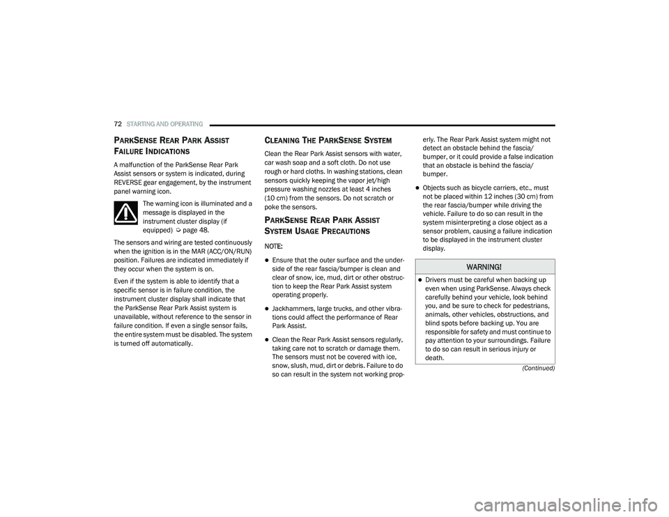
panel warning icon.
The warning icon is illuminated and a
message is displayed in the
instrument cluster display (if
equipped) Ú page 48.
The sensors and wiring are tested continuously
when the ignition is in the MAR (ACC/ON/RUN)
position. Failures are indicated immediately if
they occur when the system is on.
Even if the system is able to identify that a
specific sensor is in failure condition, the
instrument cluster display shall indicate that
the ParkSense Rear Park Assist system is
unavailable, without reference to the sensor in
failure condition. If even a single sensor fails,
the entire system must be disabled. The system
is turned off automatically.
CLEANING THE PARKSENSE SYSTEM
Clean the Rear Park Assist sensors with water,
car wash soap and a soft cloth. Do not use
rough or hard cloths. In washing stations, clean
sensors quickly keeping the vapor jet/high
pressure washing nozzles at least 4 inches
(10 cm) from the sensors. Do not scratch or
poke the sensors.
PARKSENSE REAR PARK ASSIST
S
YSTEM USAGE PRECAUTIONS
NOTE:
Ensure that the outer surface and the under -
side of the rear fascia/bumper is clean and
clear of snow, ice, mud, dirt or other obstruc -
tion to keep the Rear Park Assist system
operating properly.
Jackhammers, large trucks, and other vibra -
tions could affect the performance of Rear
Park Assist.
Clean the Rear Park Assist sensors regularly,
taking care not to scratch or damage them.
The sensors must not be covered with ice,
snow, slush, mud, dirt or debris. Failure to do
so can result in the system not working prop -erly. The Rear Park Assist system might not
detect an obstacle behind the fascia/
bumper, or it could provide a false indication
that an obstacle is behind the fascia/
bumper.
Objects such as bicycle carriers, etc., must
not be placed within 12 inches (30 cm) from
the rear fascia/bumper while driving the
vehicle. Failure to do so can result in the
system misinterpreting a close object as a
sensor problem, causing a failure indication
to be displayed in the instrument cluster
display.
WARNING!
Drivers must be careful when backing up
even when using ParkSense. Always check
carefully behind your vehicle, look behind
you, and be sure to check for pedestrians,
animals, other vehicles, obstructions, and
blind spots before backing up. You are
responsible for safety and must continue to
pay attention to your surroundings. Failure
to do so can result in serious injury or
death.
21_VF_OM_EN_USC_t.book Page 72
Page 75 of 288
STARTING AND OPERATING73
(Continued)
If it’s necessary to keep the ball mount and
hitch ball assembly mounted for a long period,
it is possible to filter out the ball mount and
hitch ball assembly presence in the sensor field
of view. The filtering operation must be
performed only by an authorized dealer.
PARKVIEW REAR BACK UP CAMERA
Your vehicle is equipped with the ParkView Rear
Back Up Camera that allows you to see an
on-screen image of the rear surroundings of
your vehicle whenever the gear selector is put
into REVERSE and/or when the rear doors are
opened. The image will be displayed on the
touchscreen display along with a caution note to “Check Entire Surroundings” across the top
of the screen. After five seconds this note will
disappear. The ParkView Rear Back Up Camera
is located on the top rear of the vehicle below
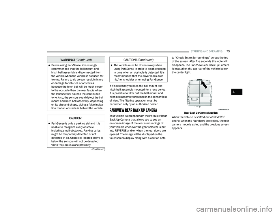
the center light.
Rear Back Up Camera Location
When the vehicle is shifted out of REVERSE
and/or when the rear doors are closed, the rear
camera mode is exited and the previous screen
appears.
Before using ParkSense, it is strongly
recommended that the ball mount and
hitch ball assembly is disconnected from
the vehicle when the vehicle is not used for
towing. Failure to do so can result in injury
or damage to vehicles or obstacles
because the hitch ball will be much closer
to the obstacle than the rear fascia when
the loudspeaker sounds the continuous
tone. Also, the sensors could detect the ball
mount and hitch ball assembly, depending
on its size and shape, giving a false indica -
tion that an obstacle is behind the vehicle.
CAUTION!
ParkSense is only a parking aid and it is
unable to recognize every obstacle,
including small obstacles. Parking curbs
might be temporarily detected or not
detected at all. Obstacles located above or
below the sensors will not be detected
when they are in close proximity.
WARNING! (Continued)
The vehicle must be driven slowly when
using ParkSense in order to be able to stop
in time when an obstacle is detected. It is
recommended that the driver looks over
his/her shoulder when using ParkSense.
CAUTION! (Continued)
4
21_VF_OM_EN_USC_t.book Page 73
Page 153 of 288

SAFETY151
(Continued)
ESC uses sensors in the vehicle to determine
the vehicle path intended by the driver and
compares it to the actual path of the vehicle.
When the actual path does not match the
intended path, ESC applies the brake of the
appropriate wheel to assist in counteracting the
oversteer or understeer condition.ESC Operating Modes
ESC OFF button Location
The ESC OFF button is located in the center
switch bank, next to the hazard flasher switch.
ESC On
This mode is the normal operating mode for ESC
equipped vehicles. Whenever the vehicle is
started, the ESC system will be in this mode.
This mode should be used for most driving
situations. ESC should only be turned off for
specific reasons as noted below.
WARNING!
Electronic Stability Control (ESC) cannot
prevent the natural laws of physics from
acting on the vehicle, nor can it increase
the traction afforded by prevailing road
conditions. ESC cannot prevent accidents,
including those resulting from excessive
speed in turns, driving on very slippery
surfaces, or hydroplaning. ESC also cannot
prevent accidents resulting from loss of
vehicle control due to inappropriate driver
input for the conditions. Only a safe, atten -
tive, and skillful driver can prevent acci -
dents. The capabilities of an ESC equipped
vehicle must never be exploited in a reck -
less or dangerous manner which could
jeopardize the user’s safety or the safety of
others.
Vehicle modifications, or failure to properly
maintain your vehicle, may change the
handling characteristics of your vehicle,
and may negatively affect the performance
of the ESC system. Changes to the steering
system, suspension, braking system, tire
type and size or wheel size may adversely
affect ESC performance. Improperly
inflated and unevenly worn tires may also
degrade ESC performance. Any vehicle
modification or poor vehicle maintenance
that reduces the effectiveness of the ESC
system can increase the risk of loss of
vehicle control, vehicle rollover, personal
injury and death.
WARNING! (Continued)
6
21_VF_OM_EN_USC_t.book Page 151
Page 156 of 288
154SAFETY
Towing With HSA
HSA will also provide assistance to mitigate roll
back while towing a trailer.
Traction Control System (TCS)
TCS monitors the amount of wheel spin of each
of the driven wheels. If wheel spin is detected,
brake pressure is applied to the slipping
wheel(s) and engine power is reduced, to
provide enhanced acceleration and stability. A
feature of the TCS, Brake Limited Differential
(BLD), functions similarly to a limited slip
differential and controls the wheel spin across a
driven axle. If one wheel on a driven axle is
spinning faster than the other, the system will
apply the brake of the spinning wheel. This will
allow more engine torque to be applied to the
wheel that is not spinning. This feature remains
active even if the ESC is in the “Partial Off”
mode.
The ESC Activation/Malfunction Indicator Light
(in the instrument cluster) will start to flash as
soon as the tires lose traction and the wheels
begin to spin. This indicates that the TCS is
active. If the indicator light flashes during
acceleration, ease up on the accelerator and
apply as little throttle as possible. Be sure to
adapt your speed and driving to the prevailing
road conditions, and do not switch off the ESC
or TCS.
Trailer Sway Control (TSC) — If Equipped
TSC uses sensors in the vehicle to recognize an
excessively swaying trailer and will take the
appropriate actions to attempt to stop the sway.
The system may reduce engine power and apply
the brake of the appropriate wheel(s) to
counteract the sway of the trailer.
WARNING!
If you use a trailer brake controller with your
trailer, the trailer brakes may be activated
and deactivated with the brake switch. If
so, there may not be enough brake pres -
sure to hold both the vehicle and the trailer
on a hill when the brake pedal is released.
In order to avoid rolling down an incline
while resuming acceleration, manually acti -
vate the trailer brake or apply more vehicle
brake pressure prior to releasing the brake
pedal.
HSA is not a parking brake. Always apply
the parking brake fully when exiting your
vehicle. Also, be certain to place the trans -
mission in PARK.
Failure to follow these warnings can result
in a collision or serious personal injury.
WARNING!
The TCS cannot prevent the natural laws of
physics from acting on the vehicle, nor can
it increase the traction afforded.
The TCS cannot prevent collisions,
including those resulting from excessive
speed in turns, or hydroplaning.
The capabilities of a TCS-equipped vehicle
must never be exploited in a reckless or
dangerous manner, which could jeopardize
the user's safety or the safety of others.
21_VF_OM_EN_USC_t.book Page 154
Page 157 of 288
SAFETY155
NOTE:
TSC cannot stop all trailers from swaying.
Always use caution when towing a trailer and
follow the trailer tongue weight recommenda -
tions Ú page 78.
When TSC is functioning, the ESC Activation/
Malfunction Indicator Light will flash, the engine
power may be reduced, and you may feel the
brakes being applied to individual wheels to
attempt to stop the trailer from swaying. TSC is
disabled when the ESC system is in the “Partial
Off” mode.AUXILIARY DRIVING SYSTEMS
BLIND SPOT MONITORING (BS M) — IF
E
QUIPPED
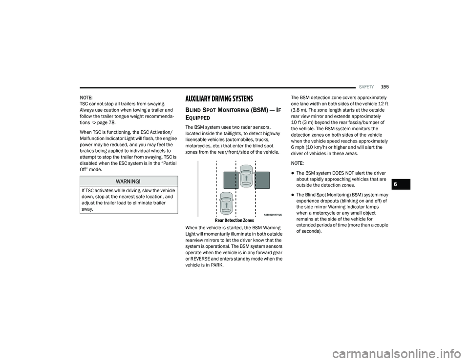
The BSM system uses two radar sensors,
located inside the taillights, to detect highway
licensable vehicles (automobiles, trucks,
motorcycles, etc.) that enter the blind spot
zones from the rear/front/side of the vehicle.
Rear Detection Zones
When the vehicle is started, the BSM Warning
Light will momentarily illuminate in both outside
rearview mirrors to let the driver know that the
system is operational. The BSM system sensors
operate when the vehicle is in any forward gear
or REVERSE and enters standby mode when the
vehicle is in PARK. The BSM detection zone covers approximately
one lane width on both sides of the vehicle 12 ft
(3.8 m). The zone length starts at the outside
rear view mirror and extends approximately
10 ft (3 m) beyond the rear fascia/bumper of
the vehicle. The BSM system monitors the
detection zones on both sides of the vehicle
when the vehicle speed reaches approximately
6 mph (10 km/h) or higher and will alert the
driver of vehicles in these areas.
NOTE:
The BSM system DOES NOT alert the driver
about rapidly approaching vehicles that are
outside the detection zones.
The Blind Spot Monitoring (BSM) system may
experience dropouts (blinking on and off) of
the side mirror Warning Indicator lamps
when a motorcycle or any small object
remains at the side of the vehicle for
extended periods of time (more than a couple
of seconds).
WARNING!
If TSC activates while driving, slow the vehicle
down, stop at the nearest safe location, and
adjust the trailer load to eliminate trailer
sway.
6
21_VF_OM_EN_USC_t.book Page 155