fog light RAM PROMASTER 2022 Owners Manual
[x] Cancel search | Manufacturer: RAM, Model Year: 2022, Model line: PROMASTER, Model: RAM PROMASTER 2022Pages: 268, PDF Size: 13.26 MB
Page 4 of 268
2
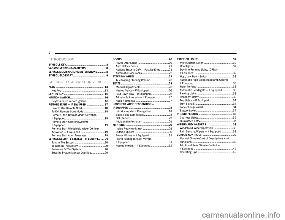
INTRODUCTION
SYMBOLS KEY ...........................................................8
VAN CONVERSIONS/CAMPERS ..............................8
VEHICLE MODIFICATIONS/ALTERATIONS .............8
SYMBOL GLOSSARY.................................................9
GETTING TO KNOW YOUR VEHICLE
KEYS ....................................................................... 13 Key Fob .............................................................13
SENTRY KEY ........................................................... 16
IGNITION SWITCH .................................................. 16
Keyless Enter ‘n Go™ Ignition .........................16
REMOTE START — IF EQUIPPED .......................... 17
How To Use Remote Start ................................18
To Exit Remote Start Mode .............................18
Remote Start Defrost Mode Activation —
If Equipped........................................................19
Remote Start Comfort Systems —
If Equipped........................................................19
Remote Start Windshield Wiper De–Icer
Activation — If Equipped ..................................19
Remote Start Abort Message ..........................19
VEHICLE SECURITY SYSTEM — IF EQUIPPED .... 20
To Arm The System ..........................................20
To Disarm The System .....................................20
Rearming Of The System .................................20
Security System Manual Override ...................20 DOORS ....................................................................20
Power Door Locks ...........................................20
Auto Unlock Doors............................................21
Keyless Enter ‘n Go™ — Passive Entry ...........21
Automatic Door Locks ......................................22
STEERING WHEEL ..................................................23
Telescoping Steering Column..........................23
SEATS ......................................................................23
Manual Adjustments ........................................23
Heated Seats — If Equipped ............................26
Fold Down Tray — If Equipped .........................26
Adjustable Armrests — If Equipped .................27
Head Restraints ..............................................27
UCONNECT VOICE RECOGNITION —
IF EQUIPPED ...........................................................28
Introducing Voice Recognition.........................28
Basic Voice Commands ...................................28
Get Started .......................................................29
Additional Information .....................................29
MIRRORS ...............................................................29
Inside Rearview Mirror .....................................29
Outside Mirrors ................................................30
Power Mirrors — If Equipped ...........................31
Power Folding Outside Mirrors —
If Equipped........................................................31
Heated Mirrors — If Equipped..........................32 EXTERIOR LIGHTS.................................................. 32
Multifunction Lever ......................................... 32
Headlights ........................................................ 32
Daytime Running Lights (DRLs) —
If Equipped ...................................................... 32
High/Low Beam Switch .................................. 33
Automatic High Beam Headlamp Control —
If Equipped .......................................................33
Flash-To-Pass .................................................. 33
Automatic Headlights — If Equipped .............. 33
Parking Lights .................................................. 33
Headlight Delay ................................................ 33
Fog Lights — If Equipped ................................. 34
Turn Signals...................................................... 34
Lane Change Assist..........................................34
Battery Saver .................................................... 34
INTERIOR LIGHTS ................................................. 35
Courtesy Lights.................................................35
Illuminated Entry .............................................. 37
WIPERS AND WASHERS ...................................... 38
Windshield Wiper Operation ........................... 38
Rain Sensing Wipers — If Equipped ................38
CLIMATE CONTROLS ............................................ 39
Manual Climate Control Descriptions And
Functions .......................................................... 39
Additional Rear Climate Control —
If Equipped .......................................................42
Operating Tips .................................................. 42
22_VF_OM_EN_USC_t.book Page 2
Page 13 of 268
11
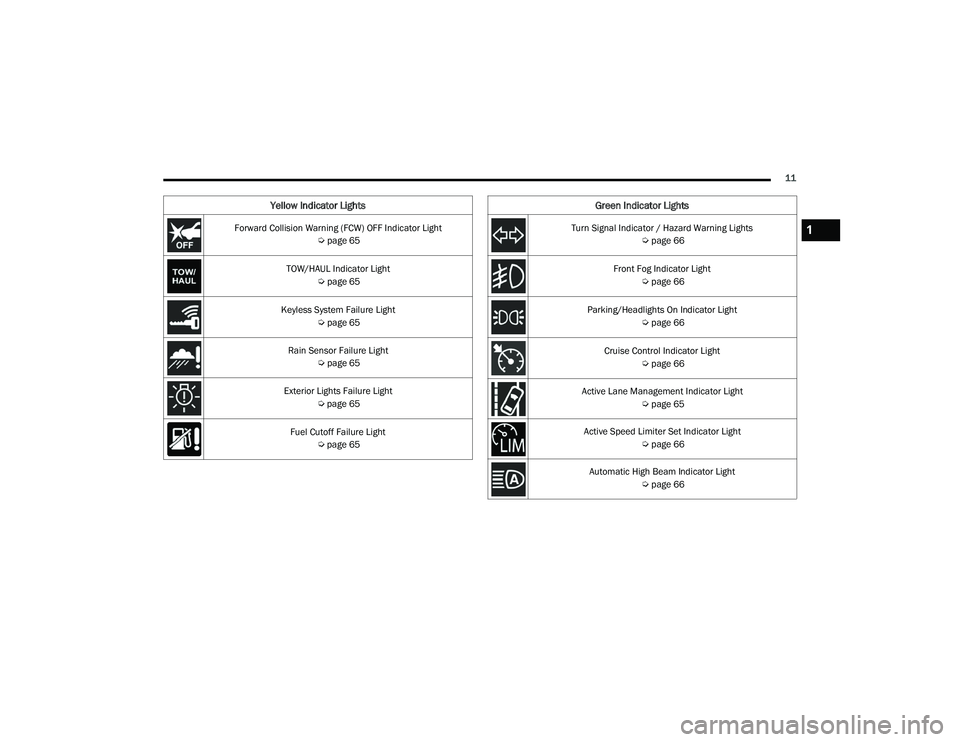
Yellow Indicator Lights
Forward Collision Warning (FCW) OFF Indicator Light Úpage 65
TOW/HAUL Indicator Light Úpage 65
Keyless System Failure Light Úpage 65
Rain Sensor Failure Light Úpage 65
Exterior Lights Failure Light Úpage 65
Fuel Cutoff Failure Light Úpage 65
Green Indicator Lights
Turn Signal Indicator / Hazard Warning Lights
Úpage 66
Front Fog Indicator Light Úpage 66
Parking/Headlights On Indicator Light Úpage 66
Cruise Control Indicator Light Úpage 66
Active Lane Management Indicator Light Úpage 65
Active Speed Limiter Set Indicator Light Úpage 66
Automatic High Beam Indicator Light Úpage 661
22_VF_OM_EN_USC_t.book Page 11
Page 34 of 268
32GETTING TO KNOW YOUR VEHICLE
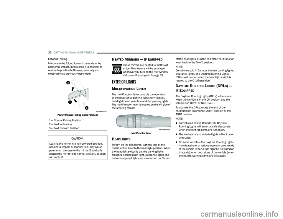
Forward Folding
Mirrors can be folded forward manually or by
accidental impact. In this case it is possible to
restore to position both ways, manually and
electrically (as previously described).
Power/Manual Folding Mirror Positions
HEATED MIRRORS — IF EQUIPPED
These mirrors are heated to melt frost
or ice. This feature will be activated
whenever you turn on the rear window
defroster (if equipped) Ú page 39.
EXTERIOR LIGHTS
MULTIFUNCTION LEVER
The multifunction lever controls the operation
of the headlights, parking lights, turn signals,
headlight beam selection and the passing lights.
The multifunction lever is located on the left side of
the steering column.
Multifunction Lever
HEADLIGHTS
To turn on the headlights, turn the end of the
multifunction lever to the headlight position. When
the headlight switch is on, the parking lights,
taillights, license plate light, clearance lights and
instrument panel lights are also turned on. To turn off the headlights, turn the end of the multifunction
lever back to the O (off) position.
NOTE:On vehicles sold in Canada, the rear parking lights,
clearance lights, and Daytime Running Lights
(DRLs) will turn on when the headlight switch is
rotated to the O (off) position.
DAYTIME RUNNING LIGHTS (DRLS) —
I
F EQUIPPED
The Daytime Running Lights (DRLs) will come on
when the ignition is in the ON position and the
vehicle is in DRIVE or NEUTRAL.
To activate the DRLs, rotate the end of the
multifunction lever to the O (off) position or the
AUTO position.
NOTE:
For vehicles sold in Canada, the Daytime
Running Lights will automatically deactivate
when the front fog lights are turned on.
The low beams and side/taillights will not be on
with DRLs.
On some vehicles, the Daytime Running Lights
may deactivate, or reduce intensity, on one side
of the vehicle (when a turn signal is activated on
that side), or on both sides of the vehicle (when
the hazard warning lights are activated).
1 — Normal Driving Position
2 — Fold In Position
3 — Fold Forward Position
CAUTION!
Leaving the mirror in a non-powered position,
accidental impact or manual fold, may cause
permanent damage to the mirror. Electrically
restore the mirror to its normal position, as soon
as practical.
22_VF_OM_EN_USC_t.book Page 32
Page 36 of 268
34GETTING TO KNOW YOUR VEHICLE
NOTE:If the headlight delay function is disabled in the
Uconnect Setting, when you put the ignition in the
OFF position with the multifunction lever already
set in the headlight position, the headlights remain
on for 8 minutes.
FOG LIGHTS — IF EQUIPPED
The fog light switch is located on the instrument
panel to the left of the steering column.
To activate the front fog lights, turn on the
parking lights or the low beam headlights
and push the fog light button. To turn off
the front fog lights, push the fog light
button a second time or turn off the headlight
switch. An indicator light in the instrument cluster
illuminates when the fog lights are turned on.
NOTE:The fog lights will operate with the low beam head -
lights or parking lights on. Selecting the high beam
headlights will turn off the fog lights.
If the vehicle’s ignition is turned off, the fog lights
will also turn off. Cornering Lights
The cornering lights are a feature to improve visibility at
night while turning the vehicle. When activated, a light
incorporated in the front fog light will illuminate on the
side of the vehicle the steering wheel is rotated or the
turn signal indicator is on. It can be activated through
the Uconnect system
Ú
page 120.
TURN SIGNALS
Move the multifunction lever up or down and the
arrows on each side of the instrument cluster will
flash to show proper operation of the front and rear
turn signals.
NOTE:When the Daytime Running Lights are on and a
turn signal is activated, the Daytime Running Lamp
will turn off on the side of the vehicle in which the
turn signal is flashing. The Daytime Running Lamp
will turn back on when the turn signal is turned off.
If either light remains on and does not flash, or
there is a very fast flash rate, check for a defective
outside light bulb.
LANE CHANGE ASSIST
Lightly push the multifunction lever up or down,
without moving beyond the detent, and the turn
signal will flash five times then automatically
turn off.
BATTERY SAVER
To protect the life of your vehicle’s battery, when
the ignition is OFF and any door is left ajar for
15 minutes, the interior lights will automatically
turn off.
NOTE:Battery saver mode is canceled if the ignition is
placed in the ON/RUN position.
22_VF_OM_EN_USC_t.book Page 34
Page 44 of 268
42GETTING TO KNOW YOUR VEHICLE
Defrost Mode
Air comes from the windshield and side
window demist outlets. When the defrost
button is selected, the blower level may
increase. Use Defrost mode with maximum
temperature settings for best windshield and side
window defrosting and defogging. When toggling the
front defrost mode button, the Climate Control system
will return to the previous setting.
Mix Mode
Air is directed through the floor, defrost,
and side window demister outlets.
This setting works best in cold or snowy
conditions that require extra heat to the
windshield. This setting is good for maintaining
comfort while reducing moisture on the
windshield.
Climate Control OFF Button
Press and release this button to turn the
Climate Control ON/OFF.
ADDITIONAL REAR CLIMATE CONTROL —
I
F EQUIPPED
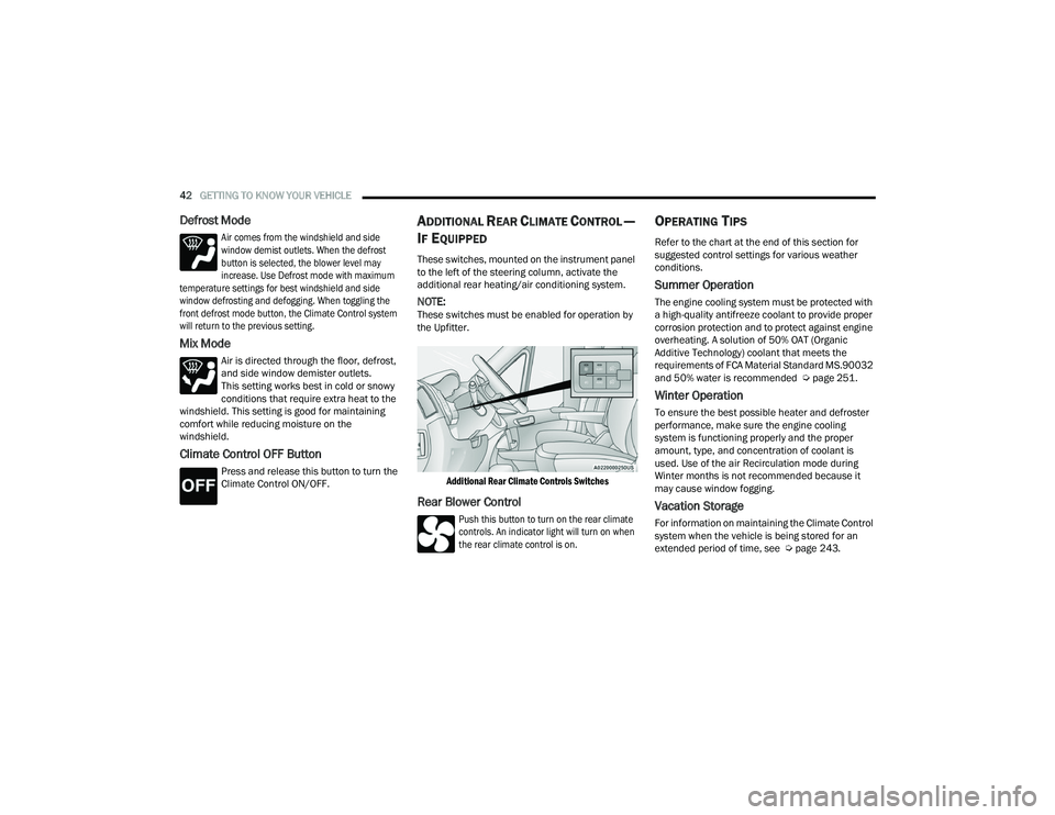
These switches, mounted on the instrument panel
to the left of the steering column, activate the
additional rear heating/air conditioning system.
NOTE:These switches must be enabled for operation by
the Upfitter.
Additional Rear Climate Controls Switches
Rear Blower Control
Push this button to turn on the rear climate
controls. An indicator light will turn on when
the rear climate control is on.
OPERATING TIPS
Refer to the chart at the end of this section for
suggested control settings for various weather
conditions.
Summer Operation
The engine cooling system must be protected with
a high-quality antifreeze coolant to provide proper
corrosion protection and to protect against engine
overheating. A solution of 50% OAT (Organic
Additive Technology) coolant that meets the
requirements of FCA Material Standard MS.90032
and 50% water is recommended Ú page 251.
Winter Operation
To ensure the best possible heater and defroster
performance, make sure the engine cooling
system is functioning properly and the proper
amount, type, and concentration of coolant is
used. Use of the air Recirculation mode during
Winter months is not recommended because it
may cause window fogging.
Vacation Storage
For information on maintaining the Climate Control
system when the vehicle is being stored for an
extended period of time, see Úpage 243.
22_VF_OM_EN_USC_t.book Page 42
Page 67 of 268

GETTING TO KNOW YOUR INSTRUMENT PANEL65
Transmission Temperature Warning Light
This warning light will illuminate to warn
of a high transmission fluid temperature.
This may occur with strenuous usage
such as trailer towing. If this light turns
on, stop the vehicle and run the engine at idle or
slightly faster, with the transmission in PARK (P) or
NEUTRAL (N), until the light turns off. Once the light
turns off, you may continue to drive normally.
YELLOW INDICATOR LIGHTS
Forward Collision Warning (FCW) OFF
Indicator Light — If Equipped
This indicator light will illuminate when
you switch FCW off or when driving
conditions obscure the sensor with snow,
heavy rain, or sun.
TOW/HAUL Indicator Light
This indicator light will illuminate when
TOW/HAUL mode is selected
Ú
page 110.
Keyless System Failure Light
The telltale will illuminate in the event of
keyless system failure.
Contact an authorized dealer as soon as possible.
Rain Sensor Failure Light
The telltale will illuminate in the case of
failure of the automatic windshield wiper.
Contact an authorized dealer as soon as
possible.
Exterior Lights Failure Light
The telltale will illuminate to indicate a
failure on the following lights: Daytime
Running Lights (DRLs) / parking lights /
trailer turn signal indicators (if present) /
trailer lights (if present) / side lights / turn signal
indicators / rear fog light / reversing light / brake
lights / license plate lights.
The failure may be caused by a blown bulb, a blown
protection fuse, or an interruption of the electrical
connection. Replace the bulb or the relevant fuse.
Contact an authorized dealer.
Fuel Cutoff Failure Light — If Equipped
This light will illuminate if there is a fuel
cutoff failure. If this light illuminates, take
it to an authorized dealer and have them
inspect it.
GREEN INDICATOR LIGHTS
Active Lane Management Indicator Light —
If Equipped
The Active Lane Management indicator light
illuminates solid green when both lane
markings have been detected and the
system is “armed” and ready to provide
visual and torque warnings if an unintentional lane
departure occurs
Ú
page 102.
WARNING!
If you continue operating the vehicle when the
Transmission Temperature Warning Light is
illuminated you could cause the fluid to boil over,
come in contact with hot engine or exhaust
components and cause a fire.
CAUTION!
Continuous driving with the Transmission
Temperature Warning Light illuminated will
eventually cause severe transmission damage
or transmission failure.
3
22_VF_OM_EN_USC_t.book Page 65
Page 68 of 268
66GETTING TO KNOW YOUR INSTRUMENT PANEL
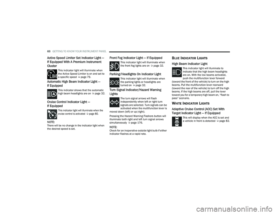
Active Speed Limiter Set Indicator Light —
If Equipped With A Premium Instrument
Cluster
This indicator light will illuminate when
the Active Speed Limiter is on and set to
a specific speed Úpage 79.
Automatic High Beam Indicator Light —
If Equipped
This indicator shows that the automatic
high beam headlights are on Úpage 32.
Cruise Control Indicator Light —
If Equipped
This indicator light will illuminate when the
cruise control is activated
Ú
page 80.
NOTE:There will be no change in the indicator light when
the desired speed is set.
Front Fog Indicator Light — If Equipped
This indicator light will illuminate when
the front fog lights are on Ú page 32.
Parking/Headlights On Indicator Light
This indicator light will illuminate when
the parking lights or headlights are
turned on Úpage 32.
Turn Signal Indicator/Hazard Warning
Lights
The turn signal arrows will flash
independently when left or right turn
signals are selected. Turn signals can be
activated when the multifunction lever is
moved down (left) or up (right).
Pressing the Hazard Warning Flashers button will
illuminate both right and left turn signal arrows
simultaneously Ú page 176.
NOTE:Check for an inoperative outside light bulb if either
indicator flashes at a rapid rate.
BLUE INDICATOR LIGHTS
High Beam Indicator Light
This indicator light will illuminate to
indicate that the high beam headlights
are on. With the low beams activated,
push the multifunction lever forward
(toward the front of the vehicle) to turn on the high
beams. Pull the multifunction lever rearward
(toward the rear of the vehicle) to turn off the high
beams. If the high beams are off, pull the lever
toward you for a temporary high beam on, “flash to
pass” scenario.
WHITE INDICATOR LIGHTS
Adaptive Cruise Control (ACC) Set With
Target Indicator Light — If Equipped
This will display when the ACC is set and
a vehicle in front is detected Ú page 82.
22_VF_OM_EN_USC_t.book Page 66
Page 131 of 268

MULTIMEDIA129
Lights
When the Lights button is pressed on the touchscreen, the system displays the options related to the vehicle’s exterior and interior lights.
NOTE:
When the “Daytime Running Lights” feature is selected, the daytime running lights can be turned on or off. This feature is only allowed by law in the country
of the vehicle purchased.
Depending on the vehicle’s options, feature settings may vary.
Setting Name Description
Headlight Off DelayThis setting will allow you to set the amount of time it takes for the headlights to shut off after the vehicle is
turned off. The available settings are “0 sec”, “30 sec”, “60 sec”, and “90 sec”.
Greeting Lights When the “Greeting Lights” feature is selected, it allows the adjustment of the amount of time the headlights
remain on after the doors are unlocked with the key fob. The available settings are “0 sec”, “30 sec”, “60 sec”,
and “90 sec”.
Auto Dim High Beams This setting will allow you to turn the Auto Dim High Beams on or off.
Daytime Running Lights This setting will allow you to turn the Daytime Running Lights on or off.
Cornering Lights When this setting is selected, if the steering wheel rotation angle is large or the turn signal indicators are on, a
light (incorporated in the fog light) will turn on, on the relevant side to improve visibility at night.
Flash Lights With Lock
This setting will allow you to turn the flashing of the lights when the Lock button is pushed on the key fob on or off.
Headlights with Wipers This setting will turn the headlights on when the wipers are activated.
5
22_VF_OM_EN_USC_t.book Page 129
Page 225 of 268

SERVICING AND MAINTENANCE223
6. Remove the (DRL), side marker bulb by pulling straight out.
7. Replace lamp as required and lock in place.
8. Reinstall plastic cap.
9. Carefully reinstall headlamp in the same position on the vehicle, as not to affect
headlamp aiming.
10. Install the one upper retaining screw on the headlamp housing.
11. Install the two lower retaining screws on the headlamp housing.
12. Carefully reinstall the lower headlamp filler panel and one retaining screw.
13. Carefully reinstall the upper headlamp filler panel and two retaining screws.
FRONT FOG LAMPS
See the following steps to replace:
1. Turn front wheels inboard to access cover in wheel liner.
2. Open the cover on the front of the wheel liner.
3. Remove connection and replace the bulb.
4. Connect the wire and rotate bulb/socket clockwise into lamp locking it in place.
5. Reinstall the plastic cap and close the cover on the wheel liner.
FRONT, REAR ROOF LAMPS
See the following steps to replace:
1. Remove two screw and remove the lamp assembly.
2. Remove the socket bulb by turning counter -
clockwise.
3. Remove bulb and replace as needed.
4. Reinstall the bulb socket and rotate clockwise to lock in place.
5. Reinstall lamp.
REAR TAIL, STOP, BACKUP, TURN SIGNAL AND
REAR SIDE MARKER LAMPS
See the following steps to replace:
1. Open rear doors.
2. Remove the seven (7) fasteners from the rear access cover and remove cover to gain access
to the tail lamp assembly fasteners.
Rear Access Cover
3. Remove the two (2) 17 mm tail lamp assembly fasteners.
4. Disconnect the tail lamp harness connector and remove tail light assembly from the
vehicle.
5. Remove the tail/stop, turn signal, backup and rear side marker bulb/socket by rotating
counterclockwise.
6. Remove the bulb and replace as needed.
7. Reinstall bulb/socket and rotate clockwise to lock in place.
8. Reinstall lamp.
8
22_VF_OM_EN_USC_t.book Page 223
Page 245 of 268

SERVICING AND MAINTENANCE243
STORING THE VEHICLE
If you are storing your vehicle for more than 3 weeks,
we recommend that you take the following steps to
minimize the drain on your vehicle's battery:
Disconnect the negative cable from the battery.
Any time you store your vehicle or keep it out of
service (i.e., vacation) for two weeks or more,
run the air conditioning system at idle for about
five minutes in the fresh air and high blower
setting prior to storing. This will ensure
adequate system lubrication to minimize the
possibility of compressor damage when the
system is started again.
BODYWORK
PROTECTION FROM ATMOSPHERIC
A
GENTS
Vehicle body care requirements vary according to
geographic locations and usage. Chemicals that make
roads passable in snow and ice and those that are
sprayed on trees and road surfaces during other
seasons are highly corrosive to the metal in your
vehicle. Outside parking, which exposes your vehicle to
airborne contaminants, road surfaces on which the
vehicle is operated, extreme hot or cold weather, and
other extreme conditions will have an adverse affect on
paint, metal trim, and underbody protection.
The following maintenance recommendations will
enable you to obtain maximum benefit from the
corrosion resistance built into your vehicle.
What Causes Corrosion?
Corrosion is the result of deterioration or removal
of paint and protective coatings from your vehicle.
The most common causes are:
Road salt, dirt and moisture accumulation
Stone and gravel impact
Insects, tree sap and tar
Salt in the air near seacoast localities
Atmospheric fallout/industrial pollutants
BODY AND UNDERBODY MAINTENANCE
Cleaning Headlights
Your vehicle is equipped with plastic headlights
and fog lights that are lighter and less susceptible
to stone breakage than glass headlights.
Plastic is not as scratch resistant as glass and
therefore different lens cleaning procedures must
be followed.
To minimize the possibility of scratching the lenses
and reducing light output, avoid wiping with a dry
cloth. To remove road dirt, wash with a mild soap
solution followed by rinsing.
Do not use abrasive cleaning components,
solvents, steel wool or other aggressive material to
clean the lenses.
WARNING!
The temperature grade for this tire is
established for a tire that is properly inflated and
not overloaded. Excessive speed, underinflation,
or excessive loading, either separately or in
combination, can cause heat buildup and
possible tire failure.
8
22_VF_OM_EN_USC_t.book Page 243