ECO mode RAM PROMASTER 2022 User Guide
[x] Cancel search | Manufacturer: RAM, Model Year: 2022, Model line: PROMASTER, Model: RAM PROMASTER 2022Pages: 268, PDF Size: 13.26 MB
Page 40 of 268
38GETTING TO KNOW YOUR VEHICLE
WIPERS AND WASHERS
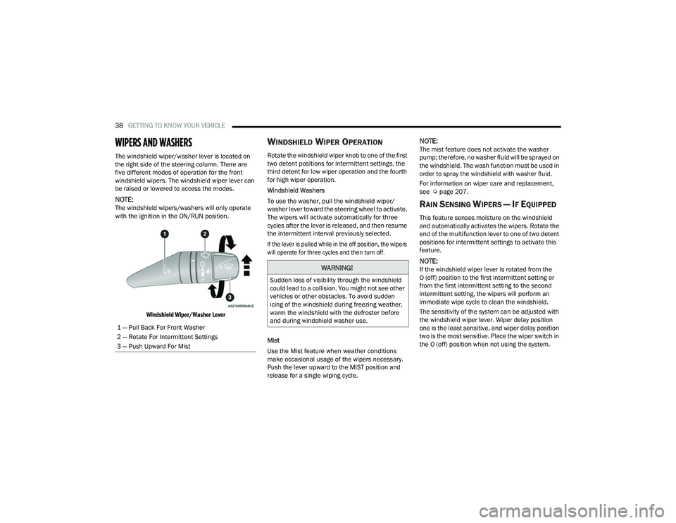
The windshield wiper/washer lever is located on
the right side of the steering column. There are
five different modes of operation for the front
windshield wipers. The windshield wiper lever can
be raised or lowered to access the modes.
NOTE:The windshield wipers/washers will only operate
with the ignition in the ON/RUN position.
Windshield Wiper/Washer Lever
WINDSHIELD WIPER OPERATION
Rotate the windshield wiper knob to one of the first
two detent positions for intermittent settings, the
third detent for low wiper operation and the fourth
for high wiper operation.
Windshield Washers
To use the washer, pull the windshield wiper/
washer lever toward the steering wheel to activate.
The wipers will activate automatically for three
cycles after the lever is released, and then resume
the intermittent interval previously selected.
If the lever is pulled while in the off position, the wipers
will operate for three cycles and then turn off.
Mist
Use the Mist feature when weather conditions
make occasional usage of the wipers necessary.
Push the lever upward to the MIST position and
release for a single wiping cycle.
NOTE:The mist feature does not activate the washer
pump; therefore, no washer fluid will be sprayed on
the windshield. The wash function must be used in
order to spray the windshield with washer fluid.
For information on wiper care and replacement,
see Úpage 207.
RAIN SENSING WIPERS — IF EQUIPPED
This feature senses moisture on the windshield
and automatically activates the wipers. Rotate the
end of the multifunction lever to one of two detent
positions for intermittent settings to activate this
feature.
NOTE:If the windshield wiper lever is rotated from the
O (off) position to the first intermittent setting or
from the first intermittent setting to the second
intermittent setting, the wipers will perform an
immediate wipe cycle to clean the windshield.
The sensitivity of the system can be adjusted with
the windshield wiper lever. Wiper delay position
one is the least sensitive, and wiper delay position
two is the most sensitive. Place the wiper switch in
the O (off) position when not using the system.
1 — Pull Back For Front Washer
2 — Rotate For Intermittent Settings
3 — Push Upward For MistWARNING!
Sudden loss of visibility through the windshield
could lead to a collision. You might not see other
vehicles or other obstacles. To avoid sudden
icing of the windshield during freezing weather,
warm the windshield with the defroster before
and during windshield washer use.
22_VF_OM_EN_USC_t.book Page 38
Page 42 of 268
40GETTING TO KNOW YOUR VEHICLE
MAX A/C Button — If Equipped
Press and release the MAX A/C button on
the touchscreen to change the current
setting to the coldest output of air.
The MAX A/C indicator illuminates when
MAX A/C is on. Pressing the button again will cause
the MAX A/C operation to exit.
A/C Button — If Equipped
Push the A/C button to engage the Air
Conditioning (A/C). The A/C indicator
illuminates when A/C is on.
NOTE:
For Manual Climate Controls, if the system is in
Mix, Floor or Defrost mode, the A/C can be
turned off, but the A/C system could remain
active to prevent fogging of the windows.
If fog or mist appears on the windshield or side
glass, select Defrost mode, and increase blower
speed if needed.
If your air conditioning performance seems
lower than expected, check the front of the A/C
condenser (located in front of the radiator), for
an accumulation of dirt or insects. Clean with a
gentle water spray from the front of the radiator
and through the condenser.
Recirculation Button
Press and release this button to change the
system between recirculation mode and
outside air mode. The Recirculation indicator
and the A/C indicator illuminate when the
Recirculation button is pressed. Recirculation can be
used when outside conditions such as smoke, odors,
dust, or high humidity are present. Recirculation can be
used in all modes except for Defrost. Recirculation may
be unavailable if conditions exist that could create
fogging on the inside of the windshield. The A/C can be
deselected manually without disturbing the mode
control selection. Continuous use of the Recirculation
mode may make the inside air stuffy and window
fogging may occur. Extended use of this mode is not
recommended. Recirculation mode may automatically
adjust to optimize customer experience for warming,
cooling, dehumidification, etc.
On systems with Manual Climate Controls, if equipped,
the Recirculation mode is not allowed in Defrost mode
to improve window clearing operation. Recirculation
is disabled automatically if this mode is selected.
Attempting to use Recirculation while in this mode
causes the LED in the control button to blink and then
turns off.
MAX Defrost Button
Push the MAX Defrost button to change
the current airflow setting to Defrost
mode. The indicator illuminates when
this feature is on. Max defrost set
maximum temperature setting for best windshield
and side window defrosting and defogging. If MAX
Defrost mode is turned off, the Climate Control
system will return to the previous setting. Air
comes from the windshield and side window
demist outlets.
Rear Defrost Button — If Equipped
Push and release the Rear Defrost
Control button to turn on the rear window
defroster and the heated outside mirrors
(if equipped). The Rear Defrost indicator
illuminates when the rear window defroster is on.
The rear window defroster automatically turns off
after 10 minutes the first time it is activated after
the first key cycle. If the key cycle is engaged again,
the rear window defroster will automatically turn
off 5 minutes after it is activated.
22_VF_OM_EN_USC_t.book Page 40
Page 44 of 268
42GETTING TO KNOW YOUR VEHICLE
Defrost Mode
Air comes from the windshield and side
window demist outlets. When the defrost
button is selected, the blower level may
increase. Use Defrost mode with maximum
temperature settings for best windshield and side
window defrosting and defogging. When toggling the
front defrost mode button, the Climate Control system
will return to the previous setting.
Mix Mode
Air is directed through the floor, defrost,
and side window demister outlets.
This setting works best in cold or snowy
conditions that require extra heat to the
windshield. This setting is good for maintaining
comfort while reducing moisture on the
windshield.
Climate Control OFF Button
Press and release this button to turn the
Climate Control ON/OFF.
ADDITIONAL REAR CLIMATE CONTROL —
I
F EQUIPPED
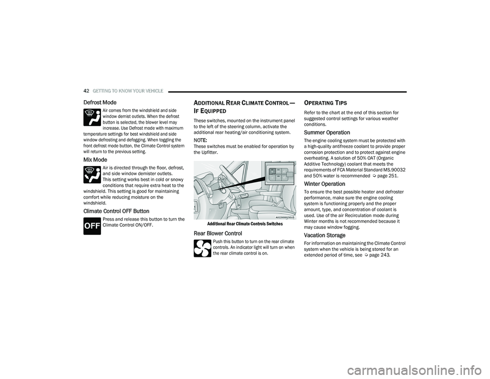
These switches, mounted on the instrument panel
to the left of the steering column, activate the
additional rear heating/air conditioning system.
NOTE:These switches must be enabled for operation by
the Upfitter.
Additional Rear Climate Controls Switches
Rear Blower Control
Push this button to turn on the rear climate
controls. An indicator light will turn on when
the rear climate control is on.
OPERATING TIPS
Refer to the chart at the end of this section for
suggested control settings for various weather
conditions.
Summer Operation
The engine cooling system must be protected with
a high-quality antifreeze coolant to provide proper
corrosion protection and to protect against engine
overheating. A solution of 50% OAT (Organic
Additive Technology) coolant that meets the
requirements of FCA Material Standard MS.90032
and 50% water is recommended Ú page 251.
Winter Operation
To ensure the best possible heater and defroster
performance, make sure the engine cooling
system is functioning properly and the proper
amount, type, and concentration of coolant is
used. Use of the air Recirculation mode during
Winter months is not recommended because it
may cause window fogging.
Vacation Storage
For information on maintaining the Climate Control
system when the vehicle is being stored for an
extended period of time, see Úpage 243.
22_VF_OM_EN_USC_t.book Page 42
Page 56 of 268
54GETTING TO KNOW YOUR INSTRUMENT PANEL
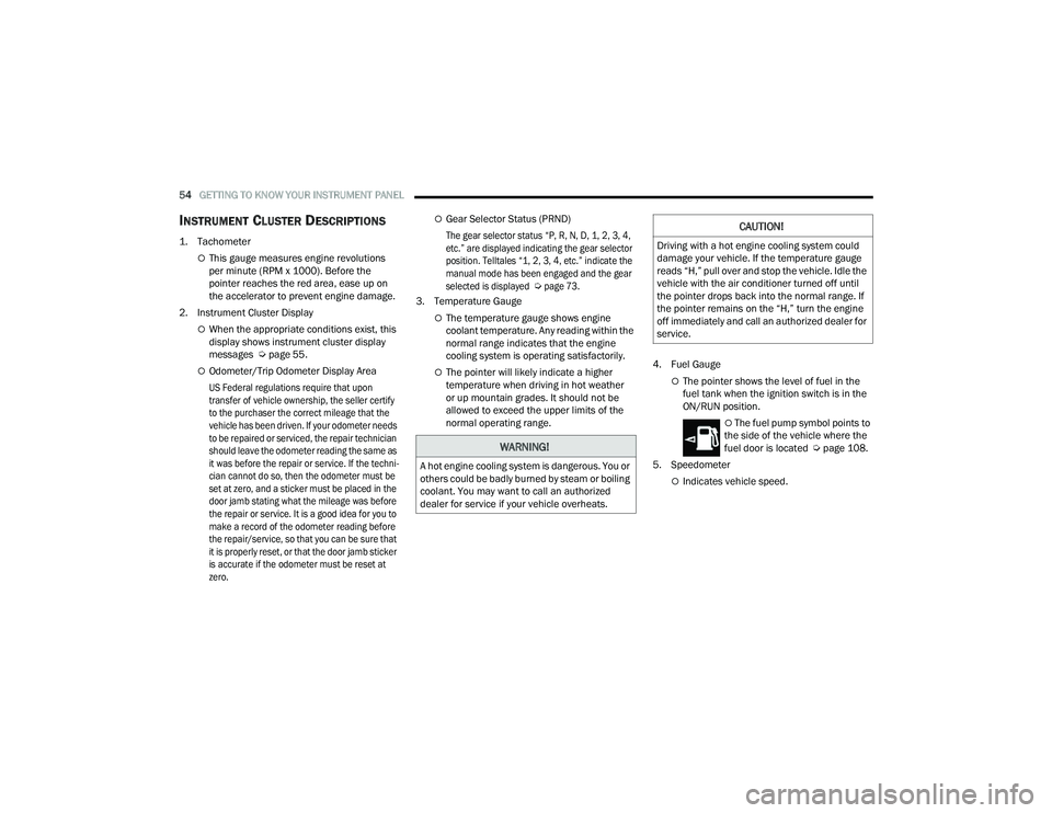
INSTRUMENT CLUSTER DESCRIPTIONS
1. Tachometer
This gauge measures engine revolutions
per minute (RPM x 1000). Before the
pointer reaches the red area, ease up on
the accelerator to prevent engine damage.
2. Instrument Cluster Display
When the appropriate conditions exist, this
display shows instrument cluster display
messages Ú page 55.
Odometer/Trip Odometer Display Area
US Federal regulations require that upon
transfer of vehicle ownership, the seller certify
to the purchaser the correct mileage that the
vehicle has been driven. If your odometer needs
to be repaired or serviced, the repair technician
should leave the odometer reading the same as
it was before the repair or service. If the techni -
cian cannot do so, then the odometer must be
set at zero, and a sticker must be placed in the
door jamb stating what the mileage was before
the repair or service. It is a good idea for you to
make a record of the odometer reading before
the repair/service, so that you can be sure that
it is properly reset, or that the door jamb sticker
is accurate if the odometer must be reset at
zero.
Gear Selector Status (PRND)
The gear selector status “P, R, N, D, 1, 2, 3, 4,
etc.” are displayed indicating the gear selector
position. Telltales “1, 2, 3, 4, etc.” indicate the
manual mode has been engaged and the gear
selected is displayed
Ú
page 73.
3. Temperature Gauge
The temperature gauge shows engine
coolant temperature. Any reading within the
normal range indicates that the engine
cooling system is operating satisfactorily.
The pointer will likely indicate a higher
temperature when driving in hot weather
or up mountain grades. It should not be
allowed to exceed the upper limits of the
normal operating range. 4. Fuel GaugeThe pointer shows the level of fuel in the
fuel tank when the ignition switch is in the
ON/RUN position.
The fuel pump symbol points to
the side of the vehicle where the
fuel door is located Ú page 108.
5. Speedometer
Indicates vehicle speed.
WARNING!
A hot engine cooling system is dangerous. You or
others could be badly burned by steam or boiling
coolant. You may want to call an authorized
dealer for service if your vehicle overheats.
CAUTION!
Driving with a hot engine cooling system could
damage your vehicle. If the temperature gauge
reads “H,” pull over and stop the vehicle. Idle the
vehicle with the air conditioner turned off until
the pointer drops back into the normal range. If
the pointer remains on the “H,” turn the engine
off immediately and call an authorized dealer for
service.
22_VF_OM_EN_USC_t.book Page 54
Page 72 of 268

70STARTING AND OPERATING
(Continued)
IF ENGINE FAILS TO START
If the engine fails to start after you have followed the
“Normal Starting” procedure, and the vehicle has not
experienced an extended park condition, it may be
flooded. Push the accelerator pedal all the way to the
floor and hold it there. Crank the engine for no more
than 10 seconds. This should clear any excess fuel in
case the engine is flooded. Leave the ignition in the
ON/RUN position, release the accelerator pedal and
repeat the “Normal Starting” procedure.
AFTER STARTING
The idle speed is controlled automatically, and it
will decrease as the engine warms up.
ENGINE BLOCK HEATER — IF EQUIPPED
The engine block heater warms the engine, and
permits quicker starts in cold weather. Connect the
cord to a standard 110-115 Volt AC electrical
outlet with a grounded, three-wire extension cord.
The engine block heater must be plugged in at
least one hour to have an adequate warming effect
on the engine.
ENGINE BREAK-IN RECOMMENDATIONS
A long break-in period is not required for the engine
and drivetrain (transmission and axle) in your
vehicle.
Drive moderately during the first 300 miles
(500 km). After the initial 60 miles (100 km),
speeds up to 50 or 55 mph (80 or 90 km/h) are
desirable.
While cruising, brief full-throttle acceleration within
the limits of local traffic laws contributes to a good
break-in. Wide-open throttle acceleration in low
gear can be detrimental and should be avoided.
The engine oil installed in the engine at the factory
is a high-quality energy conserving type lubricant.
Oil changes should be consistent with anticipated
climate conditions under which vehicle operations
will occur. For the recommended viscosity and
quality grades see Ú page 251.
CAUTION!
To prevent damage to the starter, do not crank
continuously for more than 10 seconds at a
time. Wait 10 to 15 seconds before trying again.
WARNING!
Never pour fuel or other flammable liquid into
the throttle body air inlet opening in an
attempt to start the vehicle. This could result
in flash fire causing serious personal injury.
Do not attempt to push or tow your vehicle to
get it started. Vehicles equipped with an auto -
matic transmission cannot be started this
way. Unburned fuel could enter the catalytic
converter and once the engine has started,
ignite and damage the converter and vehicle.
If the vehicle has a discharged battery,
booster cables may be used to obtain a start
from a booster battery or the battery in
another vehicle. This type of start can be
dangerous if done improperly Ú page 192.
CAUTION!
To prevent damage to the starter, do not
continuously crank the engine for more than
10 seconds at a time. Wait 10 to 15 seconds
before trying again.
WARNING!WARNING!
Remember to disconnect the engine block heater
cord before driving. Damage to the 110-115 Volt
electrical cord could cause electrocution.
CAUTION!
Never use Non-Detergent Oil or Straight Mineral
Oil in the engine or damage may result.
22_VF_OM_EN_USC_t.book Page 70
Page 75 of 268
STARTING AND OPERATING73
(Continued)
SafeHold
SafeHold is a safety feature of the Electric Park
Brake (EPB) system that will engage the parking
brake automatically if the vehicle is left unsecured
while the ignition is in ON/RUN.
The parking brake will automatically engage if all of
the following conditions are met:
The vehicle is at a standstill.
There is no attempt to press the brake pedal
and accelerator pedal.
The seat belt is unbuckled.
The driver door is open.
SafeHold can be temporarily bypassed by pushing
the EPB switch while the driver door is open. Once
manually bypassed, SafeHold will be enabled
again once the vehicle reaches 12 mph (20 km/h)
or the ignition is turned to the OFF position and
back to ON again.
Brake Service Mode
We recommend having your brakes serviced by an
authorized dealer. You should only make repairs
for which you have the knowledge and the right
equipment. You should only enter Brake Service
Mode during brake service.
When servicing your rear brakes, it may be necessary
for you or your technician to push the rear piston into
the rear caliper bore. With the Electric Park Brake (EPB)
system, this can only be done after retracting the EPB actuator. Fortunately, actuator retraction can be done
easily by entering the Brake Service Mode through the
Uconnect Settings in your vehicle. This menu-based
system will guide you through the steps necessary to
retract the EPB actuator in order to perform rear brake
service.
Service Mode has requirements that must be met
in order to be activated:
The vehicle must be at a standstill.
The parking brake must be unapplied.
The transmission must be in PARK or NEUTRAL.
While in Service Mode, the EPB fault lamp will flash
continuously while the ignition is in ON/RUN.
When brake service work is complete, the following
steps must be followed to reset the park brake
system to normal operation:
Ensure the vehicle is at a standstill.
Press the brake pedal with moderate force.
Apply the EPB Switch.
AUTOMATIC TRANSMISSION
WARNING!
You can be badly injured working on or around a
motor vehicle. Do only that service work for
which you have the knowledge and the right
equipment. If you have any doubt about your
ability to perform a service job, take your vehicle
to a competent mechanic.
WARNING!
It is dangerous to shift out of PARK or
NEUTRAL if the engine speed is higher than
idle speed. If your foot is not firmly pressing
the brake pedal, the vehicle could accelerate
quickly forward or in reverse. You could lose
control of the vehicle and hit someone or
something. Only shift into gear when the
engine is idling normally and your foot is firmly
pressing the brake pedal.
Unintended movement of a vehicle could
injure those in or near the vehicle. As with all
vehicles, you should never exit a vehicle while
the engine is running. Before exiting a vehicle,
always come to a complete stop, then apply
the parking brake, shift the transmission into
PARK, and turn the ignition off. When the igni -
tion is in the OFF position, the transmission is
locked in PARK, securing the vehicle against
unwanted movement.
When leaving the vehicle, always make sure
the ignition is in the OFF position, remove the
key fob from the vehicle, and lock the vehicle.
4
22_VF_OM_EN_USC_t.book Page 73
Page 79 of 268

STARTING AND OPERATING77
When frequent transmission shifting occurs (such
as when operating the vehicle under heavy loading
conditions, in hilly terrain, traveling into strong
head winds, or while towing a heavy trailer), select
TOW/HAUL mode or use the Electronic Range
Select (ERS) shift control to select a lower gear
range Úpage 77. Under these conditions, using a
lower gear range will improve performance and
extend transmission life by reducing excessive
shifting and heat buildup.
During cold temperatures, transmission operation
may be modified depending on engine and
transmission temperature as well as vehicle
speed. This feature improves warm-up time of the
engine and transmission to achieve maximum
efficiency. During extremely cold temperatures
(-16°F [-27°C] or below), operation may briefly be
limited to THIRD gear only. Normal operation will
resume once the transmission temperature has
risen to a suitable level.
Transmission Limp Home Mode
Transmission function is monitored electronically
for abnormal conditions. If a condition is detected
that could result in transmission damage,
Transmission Limp Home Mode is activated. In this
mode, the transmission remains in THIRD gear
regardless of which forward gear is selected.
PARK, REVERSE, and NEUTRAL will continue to operate. The Malfunction Indicator Light (MIL) may
be illuminated. Transmission Limp Home Mode
allows the vehicle to be driven to an authorized
dealer for service without damaging the
transmission.
In the event of a momentary problem, the
transmission can be reset to regain all forward
gears by performing the following steps:
1. Stop the vehicle.
2. Shift the transmission into PARK.
3. Turn the ignition OFF.
4. Wait approximately 10 seconds.
5. Restart the engine.
6. Shift into the desired gear range. If the
problem is no longer detected, the
transmission will return to normal operation.
NOTE:Even if the transmission can be reset, we
recommend that you visit an authorized dealer at
your earliest possible convenience. An authorized
dealer has diagnostic equipment to assess the
condition of your transmission. If the transmission
cannot be reset, authorized dealer service is
required.
Electronic Range Select (ERS) Operation
The ERS shift control allows the driver to
select the max gear limit. For example, if you
set the transmission gear limit to FOURTH gear, the
transmission will not shift above FOURTH gear, but
will shift through the lower gears normally.
You can switch between DRIVE and ERS mode at
any vehicle speed. When the gear selector is in the
DRIVE position, the transmission will operate
automatically, shifting between all available gears.
Moving the gear selector to the ERS position
(beside DRIVE) will activate ERS mode, display the
current gear in the instrument cluster, and set that
gear as the max gear limit. Once in ERS mode,
moving the gear selector forward “-” or rearward
“+” will change the max gear limit.
NOTE:The transmission will still continue to use the
optimal highest gear, for the current driving condi -
tions, within the selected gear range limit.
To exit ERS mode, simply return the gear selector
to the DRIVE position.
WARNING!
Do not downshift for additional engine braking
on a slippery surface. The drive wheels could
lose their grip and the vehicle could skid,
causing a collision or personal injury.
4
22_VF_OM_EN_USC_t.book Page 77
Page 80 of 268
78STARTING AND OPERATING
NOTE:To select the proper gear position for maximum
deceleration (engine braking), move the gear
selector into the ERS position, then tap it forward
“-” repeatedly as the vehicle slows. The trans -
mission will shift to the range from which the
vehicle can best be slowed down.
When To Use TOW/HAUL Mode
When driving in hilly areas, towing a trailer, carrying a
heavy load, etc., and frequent transmission shifting
occurs, push the TOW/HAUL switch to activate
TOW/HAUL mode. This will improve performance and
reduce the potential for transmission overheating or
failure due to excessive shifting. When operating in
TOW/HAUL mode, transmission upshifts are delayed,
and the transmission will automatically downshift (for
engine braking) during steady braking maneuvers.
The “TOW/HAUL Indicator Light” will illuminate in
the instrument cluster to indicate that TOW/HAUL
mode has been activated. Pushing the switch a
second time restores normal operation. Normal
operation is always the default at engine start-up. If TOW/HAUL mode is desired, the switch must be
pushed each time the engine is started.
POWER STEERING
The electric power steering system will provide
increased vehicle response and ease of
maneuverability. The power steering system
adapts to different driving conditions.
If the steering icon is flashing, it indicates that the
vehicle needs to be taken to the dealer for service.
It is likely the vehicle has lost power steering
assistance.
If the steering icon is displayed and the “POWER
STEERING SYSTEM OVER TEMP” message is
displayed on the instrument cluster screen, this
indicates an over temperature condition in the
power steering system. Once driving conditions are
safe, pull over and let the vehicle idle for a few
moments until the icon and message turn off
Ú
page 55. If the steering icon is displayed and the “SERVICE
POWER STEERING – ASSIST OFF” message is
displayed on the instrument cluster screen, this
indicates the vehicle needs to be taken to the
dealer for service Ú
page 55.NOTE:
Even if the power steering system is no longer
operational, it is still possible to steer the vehicle.
Under these conditions there will be a substantial
increase in steering effort, especially at low
speeds and during parking maneuvers.
If the condition persists, see an authorized
dealer for service.
Instrument
Cluster
Display 1
23456789D
Actual
Gear(s)
Allowed 1 1–2 1–3 1–4 1–5 1–6 1–7 1–8 1–9 1–9
22_VF_OM_EN_USC_t.book Page 78
Page 88 of 268
86STARTING AND OPERATING
NOTE:
If your vehicle is at standstill longer than two
seconds, the driver will either have to push the
RES (resume) button, or apply the accelerator
pedal to reengage the Adaptive Cruise Control
(ACC) to the existing set speed.
ACC cannot be resumed if there is a stationary
vehicle in front of your vehicle in close proximity.
To Vary The Speed Setting
To Increase Or Decrease The Set Speed
After setting a speed, you can increase the set
speed by pushing the SET (+) button, or decrease
speed by pushing the SET (-) button. U.S. Speed (mph)
Pushing the SET (+)
, or SET (-) button once will
result in a 1 mph speed adjustment. Each
subsequent tap of the button results in an
adjustment of 1 mph.
If the button is continually pushed, the set speed
will continue to adjust in 5 mph increments until
the button is released. The new set speed is
reflected in the instrument cluster display.
Metric Speed (km/h)
Pushing the SET (+) , or SET (-) button once will
result in a 1 km/h speed adjustment. Each
subsequent tap of the button results in an
adjustment of 1 km/h.
If the button is continually pushed, the set speed
will continue to adjust in 10 km/h increments
until the button is released. The new set speed is
reflected in the instrument cluster display.
NOTE:When you override and push the SET (+) button or
SET (-) button, the new set speed will be the current
speed of the vehicle.
When ACC Is Active
When you use the SET (-) button to decelerate, if
the engine’s braking power does not slow the
vehicle sufficiently to reach the set speed, the
brake system will automatically slow the vehicle.
The ACC system decelerates the vehicle to a full
stop when following the vehicle in front. If your
vehicle follows the vehicle in front to a standstill,
after two seconds the driver will either have to
push the RES (resume) button, or apply the
accelerator pedal to reengage the ACC to the
existing set speed.
The ACC system maintains set speed when
driving uphill and downhill. However, a slight
speed change on moderate hills is normal.
In addition, downshifting may occur while
climbing uphill or descending downhill. This is
normal operation and necessary to maintain set
speed. When driving uphill and downhill, the
ACC system will cancel if the braking tempera -
ture exceeds normal range (overheated).
Setting The Following Distance In ACC
The specified following distance for ACC can be set
by varying the distance setting between four bars
(longest), three bars (long), two bars (medium) and
one bar (short). Using this distance setting and
the vehicle speed, ACC calculates and sets the
distance to the vehicle ahead. This distance
setting will show in the instrument cluster display.
WARNING!
The Resume function should only be used if traffic
and road conditions permit. Resuming a set speed
that is too high or too low for prevailing traffic and
road conditions could cause the vehicle to
accelerate or decelerate too sharply for safe
operation. Failure to follow these warnings can result
in a collision and death or serious personal injury.
22_VF_OM_EN_USC_t.book Page 86
Page 93 of 268
STARTING AND OPERATING91
TRAFFIC SIGN ASSIST SYSTEM —
IF EQUIPPED
The Traffic Sign Assist (TSA) system uses a camera
mounted on the windshield, as well as map data
when the vehicle is equipped with Navigation, to
detect recognizable road signs such as:
Speed limits
School zones
No passing zones
NOTE:
The TSA system will automatically display the
road sign detected in the unit of measurement
(mph or km/h) selected within Uconnect
Settings or within the instrument cluster display.
If no speed limit signs are detected, the system
will revert to the speed limit signs that are
stored in the Navigation system.
The system always checks the traffic signs indi -
cating the current speed limit signs. The system
is able to recognize and display up to two
different road signs in the instrument cluster
display.
ACTIVATION/DEACTIVATION
The TSA System can be enabled/disabled within
the Uconnect system through the Safety/Driver
Assistance menu. System ON is signaled by road
signs shown on the instrument cluster display.
NOTE:Even if the system is OFF, the speed limit sign will
be displayed when the driver selects it in the HOME
screen.
TRAFFIC SIGN ASSIST MODES
TSA has three selectable modes of operation that
are available through the Uconnect system.
Visual
When Visual is selected, the system will alert the
driver when the current speed of the vehicle
exceeds the detected speed limit by showing a
graphic in the instrument cluster display.
Visual + Chime
When Visual + Chime is selected, the system will
alert the driver when the current speed of the vehicle
exceeds the detected speed limit by showing a
graphic in the instrument cluster display, and by
sounding an audible alert. The audible alert will last
for 10 seconds, and the visual alert will remain on as
long as the vehicle is exceeding the speed limit.
TSA Off
When the TSA system is turned off, the system will
not show any traffic signs (unless selected in the
HOME screen, which will show detected speed
limit signs), and no alerts will be issued to the
driver.
INDICATIONS ON THE DISPLAY
Detected traffic signs are shown in the instrument
cluster display, and can display any combination of
signs at one time (e.g. speed limit, speed limit and
supplemental info, and “Do Not Pass” signs)
depending on what information is available.
When a newly detected speed limit is higher than
the current speed limit, the display will update
along with an “up” arrow.
When a newly detected speed limit is lower than
the current speed limit, the display will update
along with a “down” arrow.
4
22_VF_OM_EN_USC_t.book Page 91