check engine RAM PROMASTER 2022 Owners Manual
[x] Cancel search | Manufacturer: RAM, Model Year: 2022, Model line: PROMASTER, Model: RAM PROMASTER 2022Pages: 268, PDF Size: 13.26 MB
Page 7 of 268
5
SAFETY TIPS ........................................................ 172 Transporting Passengers .............................. 172Transporting Pets ......................................... 173
Connected Vehicles....................................... 173
Safety Checks You Should Make Inside
The Vehicle ................................................... 173Periodic Safety Checks You Should Make
Outside The Vehicle ...................................... 174Exhaust Gas ................................................... 175Carbon Monoxide Warnings ......................... 175
IN CASE OF EMERGENCY
HAZARD WARNING FLASHERS ......................... 176
SOS AND ASSIST SYSTEM ................................. 176
JACKING AND TIRE CHANGING.......................... 180
Preparations For Jacking .............................. 180Jack Location — If Equipped ......................... 181Spare Tire Removal ....................................... 182
Jacking Instructions ...................................... 184Wheel Covers ................................................. 187
TIRE SERVICE KIT — IF EQUIPPED ..................... 187
Tire Service Kit Storage ................................ 187
Tire Service Kit Components And
Operation ....................................................... 187
Tire Service Kit Usage Precautions .............. 188
Sealing A Tire With Tire Service Kit .............. 189
JUMP STARTING................................................... 192
Preparations For Jump Start......................... 192Jump Starting Procedure .............................. 193Battery Location ............................................ 194 IF YOUR ENGINE OVERHEATS .......................... 194
GEAR SELECTOR OVERRIDE ............................. 195
FREEING A STUCK VEHICLE .............................. 196
TOWING A DISABLED VEHICLE ......................... 196 Automatic Transmission ............................... 197
ENHANCED ACCIDENT RESPONSE
SYSTEM (EARS) ................................................... 197
EVENT DATA RECORDER (EDR) ........................ 197
SERVICING AND MAINTENANCE
SCHEDULED SERVICING ................................... 198
Maintenance Plan ......................................... 199
ENGINE COMPARTMENT .................................... 202
3.6L Engine .................................................. 202
Checking Oil Level ......................................... 203
Adding Washer Fluid ..................................... 203
Maintenance-Free Battery ........................... 204Pressure Washing ......................................... 204
VEHICLE MAINTENANCE..................................... 204
Engine Oil ....................................................... 205
Engine Oil Filter ............................................. 205Engine Air Cleaner Filter .............................. 205Air Conditioner Maintenance ....................... 206
Body Lubrication ........................................... 207Windshield Wiper Blades ............................. 207
Exhaust System ............................................ 208
Cooling System .............................................. 209
Brake System ............................................... 211
Automatic Transmission ............................... 212 Fuses.............................................................. 213
Bulb Replacement ....................................... 220
TIRES .................................................................... 225
Tire Safety Information ................................ 225Tires — General Information ......................... 233
Tire Types....................................................... 236Spare Tires — If Equipped ............................ 237
Wheel And Wheel Trim Care ........................ 239Snow Traction Devices ................................. 240
Tire Rotation Recommendations ................. 241
DEPARTMENT OF TRANSPORTATION UNIFORM
TIRE QUALITY GRADES ...................................... 242
Treadwear...................................................... 242
Traction Grades ............................................. 242Temperature Grades..................................... 242
STORING THE VEHICLE ...................................... 243
BODYWORK .......................................................... 243
Protection From Atmospheric Agents .......... 243
Body And Underbody Maintenance ............. 243
Preserving The Bodywork ............................. 244
INTERIORS ........................................................... 244
Seats And Fabric Parts ................................. 244
Plastic And Coated Parts .............................. 245
Leather Surfaces........................................... 245
Glass Surfaces ............................................. 246Cleaning The Instrument Panel
Cupholders .................................................... 246
22_VF_OM_EN_USC_t.book Page 5
Page 12 of 268
10
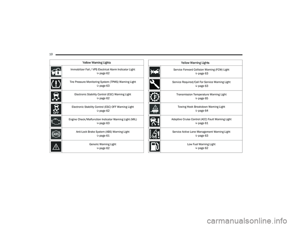
Yellow Warning Lights
Immobilizer Fail / VPS Electrical Alarm Indicator Light Úpage 62
Tire Pressure Monitoring System (TPMS) Warning Light Úpage 63
Electronic Stability Control (ESC) Warning Light Úpage 62
Electronic Stability Control (ESC) OFF Warning Light Úpage 62
Engine Check/Malfunction Indicator Warning Light (MIL) Úpage 63
Anti-Lock Brake System (ABS) Warning Light Úpage 61
Generic Warning Light Úpage 62Service Forward Collision Warning (FCW) Light
Úpage 63
Service Required/Call For Service Warning Light Úpage 63
Transmission Temperature Warning Light Úpage 65
Towing Hook Breakdown Warning Light Úpage 64
Adaptive Cruise Control (ACC) Fault Warning Light Úpage 61
Service Active Lane Management Warning Light Úpage 63
Low Fuel Warning Light Úpage 62
Yellow Warning Lights
22_VF_OM_EN_USC_t.book Page 10
Page 16 of 268

14GETTING TO KNOW YOUR VEHICLE
To Lock/Unlock The Doors
To lock all of the doors, push and release the lock
button once. Push and release the front unlock
button on key fob once to unlock only the front
doors (figure 1) or push and release the unlock
button on key fob once to unlock all doors (figure
2). Push and release the cargo unlock button on
key fob once to unlock the cargo area (rear lateral
sliding doors and rear door). The doors can also
be locked and unlocked manually by using the
mechanical key.
When the doors are unlocked, the turn signals will
flash. When the doors are locked, the turn signals will
flash and the horn will chirp (if equipped and activated
through the Uconnect Settings
Ú
page 120). If a door
is open when the lock button is pushed, the turn signal
lights will flash at an increased rate to indicate that a
door is still open.
Key Left Vehicle Feature
If a valid key fob is no longer detected inside the
vehicle while the vehicle’s ignition system is in the
ON/RUN or START position, the message “Key Fob
Has Left The Vehicle” will be shown in the
instrument cluster display along with an interior
chime. An exterior audible and visual alert will also
be activated to warn the driver. The vehicle’s horn will rapidly chirp three times
along with a single flash of the vehicle’s exterior
lights.
NOTE:
The doors have to be open and then closed in
order for the vehicle to check for the presence of
a key fob; the Key Left Vehicle feature will not
activate until all of the doors are closed.
These alerts will not be activated in situations
where the vehicle’s engine is left running with
the key fob inside.
Replacing The Battery In The Key Fob
The replacement battery is one CR2032 battery.
NOTE:
Customers are recommended to use a battery
obtained from Mopar®. Aftermarket coin
battery dimensions may not meet the original
OEM coin battery dimensions.
Perchlorate Material — special handling may apply.
See
www.dtsc.ca.gov/hazardouswaste/
perchlorate
for further information.
Do not touch the battery terminals that are on
the back housing or the printed circuit board.
1. Remove the emergency key (2) by sliding the
emergency key release (1) on the back of the
key fob and pulling the emergency key out
with your other hand.
Emergency Key Removal
1 — Emergency Key Release Button
2 — Emergency Key
22_VF_OM_EN_USC_t.book Page 14
Page 54 of 268
52GETTING TO KNOW YOUR INSTRUMENT PANEL
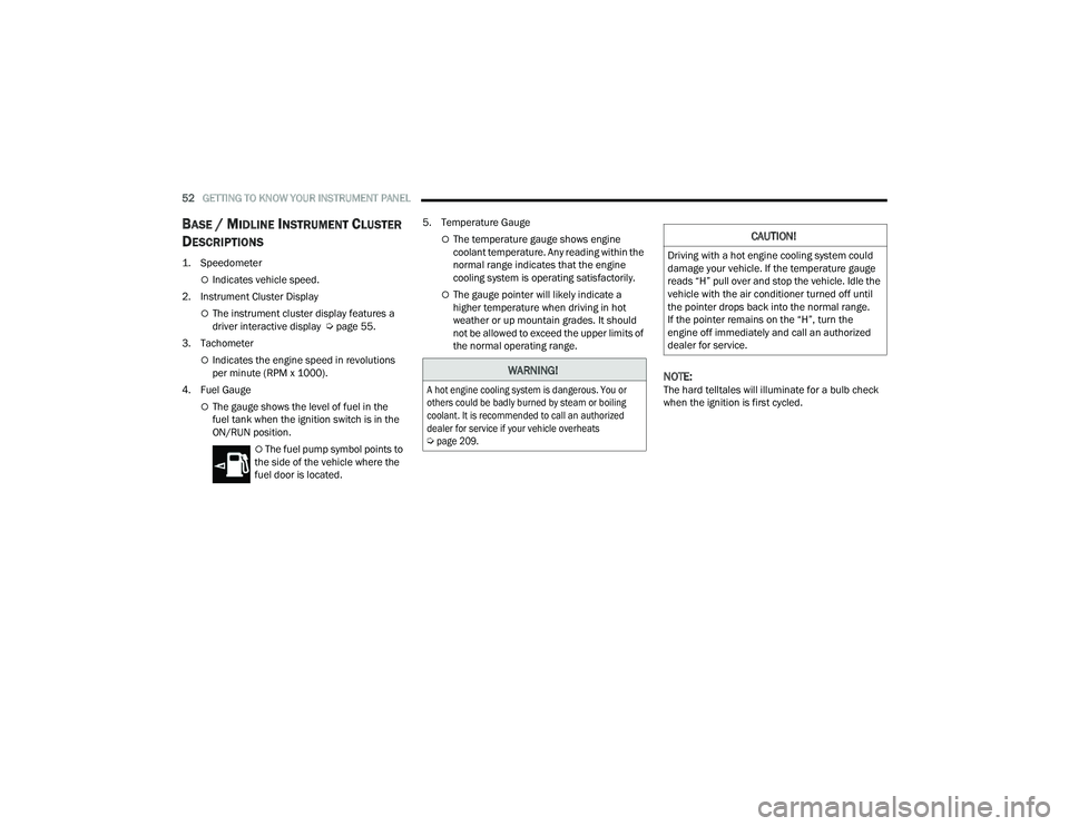
BASE / MIDLINE INSTRUMENT CLUSTER
D
ESCRIPTIONS
1. Speedometer
Indicates vehicle speed.
2. Instrument Cluster Display
The instrument cluster display features a
driver interactive display Ú page 55.
3. Tachometer
Indicates the engine speed in revolutions
per minute (RPM x 1000).
4. Fuel Gauge
The gauge shows the level of fuel in the
fuel tank when the ignition switch is in the
ON/RUN position.
The fuel pump symbol points to
the side of the vehicle where the
fuel door is located. 5. Temperature Gauge
The temperature gauge shows engine
coolant temperature. Any reading within the
normal range indicates that the engine
cooling system is operating satisfactorily.
The gauge pointer will likely indicate a
higher temperature when driving in hot
weather or up mountain grades. It should
not be allowed to exceed the upper limits of
the normal operating range.
NOTE:The hard telltales will illuminate for a bulb check
when the ignition is first cycled.
WARNING!
A hot engine cooling system is dangerous. You or
others could be badly burned by steam or boiling
coolant. It is recommended to call an authorized
dealer for service if your vehicle overheats
Ú
page 209.
CAUTION!
Driving with a hot engine cooling system could
damage your vehicle. If the temperature gauge
reads “H” pull over and stop the vehicle. Idle the
vehicle with the air conditioner turned off until
the pointer drops back into the normal range.
If the pointer remains on the “H”, turn the
engine off immediately and call an authorized
dealer for service.
22_VF_OM_EN_USC_t.book Page 52
Page 62 of 268
60GETTING TO KNOW YOUR INSTRUMENT PANEL
The light also will turn on when the parking brake
is applied with the ignition switch in the ON/RUN
position.
NOTE:This light shows only that the parking brake is
applied. It does not show the degree of brake
application.
Battery Charge Warning Light
This warning light will illuminate when the
battery is not charging properly. If it stays
on while the engine is running, there may
be a malfunction with the charging
system. Contact an authorized dealer as soon as
possible.
This indicates a possible problem with the
electrical system or a related component.
Door Open Warning Light
This indicator will illuminate when one or
more door(s) are not fully closed. A pop-up
appears on the instrument cluster display
showing which door is open.
NOTE:If the vehicle is moving and a door is opened, there
will also be a single chime.
Electric Power Steering (EPS) Fault
Warning Light
This warning light will turn on when
there's a fault with the EPS system
Ú page 78.
Electronic Throttle Control (ETC) Warning
Light
This warning light will illuminate to inform of
a problem with the ETC system. If a problem
is detected while the vehicle is running, the
light will either stay on or flash depending on
the nature of the problem. Cycle the ignition when the
vehicle is safely and completely stopped and the
transmission is placed in the PARK (P) position. The
light should turn off. If the light remains on with the
vehicle running, your vehicle will usually be drivable;
however, see an authorized dealer for service as soon
as possible.
If the light continues to flash when the vehicle is
running, immediate service is required and you
may experience reduced performance, an
elevated/rough idle, or engine stall and your
vehicle may require towing. The light will come
on when the ignition is placed in the ON/RUN or
MAR/ON/RUN position and remain on briefly as a
bulb check. If the light does not come on during
starting, have the system checked by an
authorized dealer.
Engine Temperature Warning Light
This light warns of an overheated engine
condition. If the engine coolant
temperature is too high, this indicator will
illuminate and a single chime will sound.
If the light turns on while driving, safely pull over and
stop the vehicle. If the Air Conditioning (A/C) system is
on, turn it off. Also, shift the transmission into NEUTRAL
and idle the vehicle. If the temperature reading does
not return to normal, turn the engine off immediately
and call for service
Ú
page 194.
Hood Open Warning Light
The telltale turns on when the hood is not
properly closed. Along with the icon, an
image of the vehicle with an open hood
cap appears on the display.
Close the hood properly.
WARNING!
Continued operation with reduced assist could
pose a safety risk to yourself and others. Service
should be obtained as soon as possible.
22_VF_OM_EN_USC_t.book Page 60
Page 63 of 268
GETTING TO KNOW YOUR INSTRUMENT PANEL61
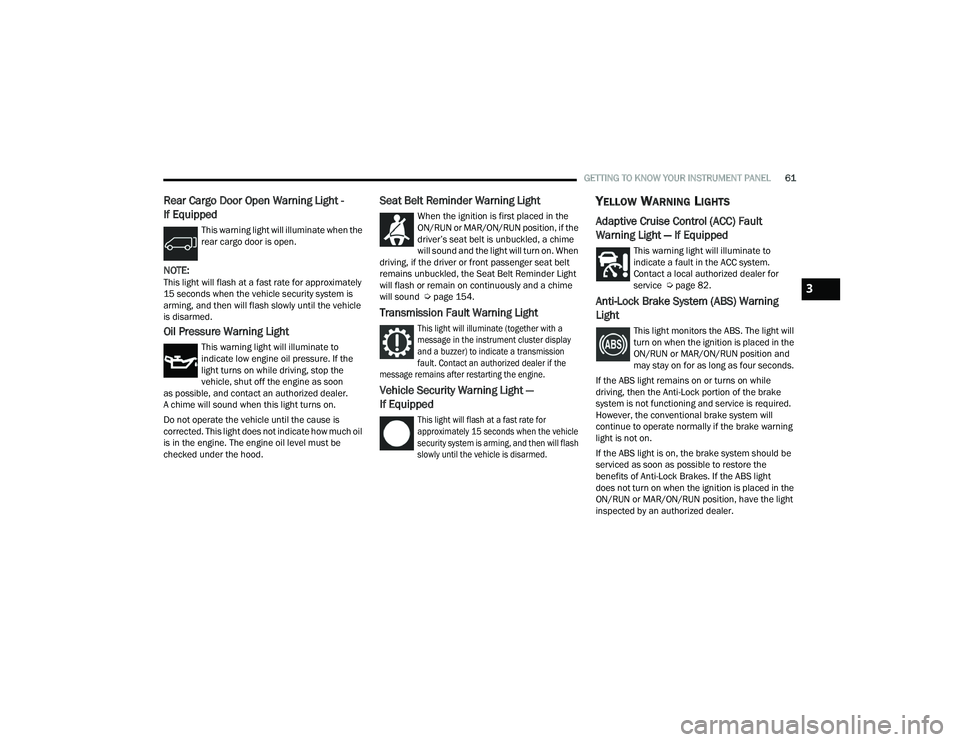
Rear Cargo Door Open Warning Light -
If Equipped
This warning light will illuminate when the
rear cargo door is open.
NOTE:This light will flash at a fast rate for approximately
15 seconds when the vehicle security system is
arming, and then will flash slowly until the vehicle
is disarmed.
Oil Pressure Warning Light
This warning light will illuminate to
indicate low engine oil pressure. If the
light turns on while driving, stop the
vehicle, shut off the engine as soon
as possible, and contact an authorized dealer.
A chime will sound when this light turns on.
Do not operate the vehicle until the cause is
corrected. This light does not indicate how much oil
is in the engine. The engine oil level must be
checked under the hood.
Seat Belt Reminder Warning Light
When the ignition is first placed in the
ON/RUN or MAR/ON/RUN position, if the
driver’s seat belt is unbuckled, a chime
will sound and the light will turn on. When
driving, if the driver or front passenger seat belt
remains unbuckled, the Seat Belt Reminder Light
will flash or remain on continuously and a chime
will sound Ú page 154.
Transmission Fault Warning Light
This light will illuminate (together with a
message in the instrument cluster display
and a buzzer) to indicate a transmission
fault. Contact an authorized dealer if the
message remains after restarting the engine.
Vehicle Security Warning Light —
If Equipped
This light will flash at a fast rate for
approximately 15 seconds when the vehicle
security system is arming, and then will flash
slowly until the vehicle is disarmed.
YELLOW WARNING LIGHTS
Adaptive Cruise Control (ACC) Fault
Warning Light — If Equipped
This warning light will illuminate to
indicate a fault in the ACC system.
Contact a local authorized dealer for
service Ú page 82.
Anti-Lock Brake System (ABS) Warning
Light
This light monitors the ABS. The light will
turn on when the ignition is placed in the
ON/RUN or MAR/ON/RUN position and
may stay on for as long as four seconds.
If the ABS light remains on or turns on while
driving, then the Anti-Lock portion of the brake
system is not functioning and service is required.
However, the conventional brake system will
continue to operate normally if the brake warning
light is not on.
If the ABS light is on, the brake system should be
serviced as soon as possible to restore the
benefits of Anti-Lock Brakes. If the ABS light
does not turn on when the ignition is placed in the
ON/RUN or MAR/ON/RUN position, have the light
inspected by an authorized dealer.
3
22_VF_OM_EN_USC_t.book Page 61
Page 65 of 268

GETTING TO KNOW YOUR INSTRUMENT PANEL63
Engine Check/Malfunction Indicator (MIL)
Warning Light
The Engine Check/Malfunction Indicator
Light (MIL) is a part of an Onboard
Diagnostic System called OBD II that
monitors engine and automatic
transmission control systems. This warning light
will illuminate when the ignition is in the ON/RUN
position before engine start. If the bulb does not
come on when turning the ignition switch from OFF
to ON/RUN, have the condition checked promptly.
Certain conditions, such as a loose or missing gas
cap, poor quality fuel, etc., may illuminate the light
after engine start. The vehicle should be serviced if
the light stays on through several typical driving
styles. In most situations, the vehicle will drive
normally and will not require towing.
When the engine is running, the MIL may flash to
alert serious conditions that could lead to immediate
loss of power or severe catalytic converter damage.
The vehicle should be serviced by an authorized dealer
as soon as possible if this occurs.
Service Active Lane Management Warning
Light — If Equipped
This warning light will illuminate when the
Active Lane Management system is not
operating and requires service. Please
see an authorized dealer.
Service Forward Collision Warning (FCW)
Light — If Equipped
This warning light will illuminate to
indicate a fault in the FCW System.
Contact an authorized dealer for service.
Service Required/Call For Service Warning
Light
This warning light will illuminate when
service is needed. A pop-up will appear in
the display to signal the need for service.
Contact an authorized dealer as soon as
possible.
Tire Pressure Monitoring System (TPMS)
Warning Light
The warning light switches on and a message
is displayed to indicate that the tire pressure
is lower than the recommended value and/
or that slow pressure loss is occurring. In
these cases, optimal tire duration and fuel
consumption may not be guaranteed.
Should one or more tires be in the condition
mentioned above, the display will show the
indications corresponding to each tire.
WARNING!
A malfunctioning catalytic converter, as referenced
above, can reach higher temperatures than in
normal operating conditions. This can cause a fire if
you drive slowly or park over flammable substances
such as dry plants, wood, cardboard, etc. This could
result in death or serious injury to the driver,
occupants or others.
CAUTION!
Prolonged driving with the Malfunction Indicator
Light (MIL) on could cause damage to the vehicle
control system. It also could affect fuel economy and
driveability. If the MIL is flashing, severe catalytic
converter damage and power loss will soon occur.
Immediate service is required.
3
22_VF_OM_EN_USC_t.book Page 63
Page 70 of 268

68GETTING TO KNOW YOUR INSTRUMENT PANEL
ONBOARD DIAGNOSTIC SYSTEM
(OBD II) C
YBERSECURITY
Your vehicle is required to have an OBD II and a
connection port to allow access to information
related to the performance of your emissions
controls. Authorized service technicians may need
to access this information to assist with the
diagnosis and service of your vehicle and
emissions system Ú page 119.
EMISSIONS INSPECTION AND
MAINTENANCE PROGRAMS
In some localities, it may be a legal requirement to
pass an inspection of your vehicle's emissions
control system. Failure to pass could prevent
vehicle registration.
For states that require an Inspection and
Maintenance (I/M), this check verifies
the Malfunction Indicator Light (MIL) is
functioning and is not on when the
engine is running, and that the OBD II system is
ready for testing.
The OBD II system may not be ready if your vehicle
was recently serviced, recently had a depleted
battery or a battery replacement. If the OBD II
system should be determined not ready for the I/M
test, your vehicle may fail the test.
Your vehicle has a simple ignition actuated test,
which you can use prior to going to the test station.
To check if your vehicle's OBD II system is ready,
you must do the following:
1. Switch the ignition to the ON position, but do not crank or start the engine.
NOTE:If you crank or start the engine, you will have to
start this test over. 2. As soon as you cycle the ignition switch to the
ON position, you will see the Malfunction
Indicator Light (MIL) symbol come on as part of
a normal bulb check.
3. Approximately 15 seconds later, one of two things will happen:
The MIL will flash for about 10 seconds and
then return to being fully illuminated until you
turn OFF the ignition or start the engine. This
means that your vehicle's OBD II system is not
ready and you should not proceed to the I/M
station.
The MIL will not flash at all and will remain fully
illuminated until you place the ignition in the off
position or start the engine. This means that
your vehicle's OBD II system is ready and you
can proceed to the I/M station.
If your OBD II system is not ready, you should see
an authorized dealer or repair facility. If your
vehicle was recently serviced or had a battery
failure or replacement, you may need to do nothing
more than drive your vehicle as you normally would
in order for your OBD II system to update. A
recheck with the above test routine may then
indicate that the system is now ready.
WARNING!
ONLY an authorized service technician should
connect equipment to the OBD II connection
port in order to read the VIN, diagnose, or
service your vehicle.
If unauthorized equipment is connected to the
OBD II connection port, such as a
driver-behavior tracking device, it may:
Be possible that vehicle systems,
including safety related systems, could be
impaired or a loss of vehicle control could
occur that may result in an accident
involving serious injury or death.
Access, or allow others to access, infor -
mation stored in your vehicle systems,
including personal information.
22_VF_OM_EN_USC_t.book Page 68
Page 73 of 268

STARTING AND OPERATING71
NOTE:A new engine may consume some oil during its first
few thousand miles (kilometers) of operation. This
should be considered a normal part of the break-in
and not interpreted as a problem. Please check
your oil level with the engine oil indicator often
during the break-in period. Add oil as required.
PARKING BRAKE
ELECTRIC PARK BRAKE (EPB)
Your vehicle is equipped with an EPB that offers
simple operation, and some additional features
that make the parking brake more convenient and
useful.
The parking brake is primarily intended to prevent
the vehicle from rolling while parked. Before
leaving the vehicle, make sure that the parking
brake is applied. Also, be certain to leave the
transmission in PARK.
You can engage the parking brake in two ways:
Manually, by applying the parking brake switch.
Automatically, by enabling the Auto Park Brake
feature in the Customer Programmable
Features section of the Uconnect settings.
The parking brake switch is located on the
instrument panel to the left of the steering wheel
(below the headlamp switch).
Electric Park Brake Switch
To apply the parking brake manually, pull up on the
switch momentarily. You may hear a slight sound from
the back of the vehicle while the parking brake
engages. Once the park brake is fully engaged, the
BRAKE telltale light in the instrument cluster and an
indicator on the switch will illuminate. If your foot is on
the brake pedal while you apply the parking brake, you
may notice a small amount of brake pedal movement.
The parking brake can be applied even when the
ignition switch is OFF but the BRAKE telltale light will
not illuminate, however, it can only be released when
the ignition is in the ON/RUN position.
NOTE:The EPB fault light will illuminate if the EPB switch
is held for longer than 20 seconds in either the
released or applied position. The light will extin -
guish upon releasing the switch. If the Auto Park Brake feature is enabled, the
parking brake will automatically engage whenever
the transmission is placed into PARK. If your foot is
on the brake pedal, you may notice a small amount
of brake pedal movement while the parking brake
is engaging.
The parking brake will release automatically when
the ignition is ON, the transmission is in DRIVE or
REVERSE, the driver seat belt is buckled, and an
attempt is made to drive away.
To release the parking brake manually, the ignition
switch must be in the ON/RUN position. Put your
foot on the brake pedal, then push the parking
brake switch down momentarily. You may hear a
slight whirring sound from the back of the vehicle
while the parking brake disengages. You may also
notice a small amount of movement in the brake
pedal. Once the parking brake is fully disengaged,
the BRAKE telltale light in the instrument cluster
and the LED indicator on the switch will extinguish.
NOTE:When parking on a hill, it is important to turn the
front wheels toward the curb on a downhill grade
and away from the curb on an uphill grade. Apply
the parking brake before placing the gear selector
in PARK, otherwise the load on the transmission
locking mechanism may make it difficult to move
the gear selector out of PARK.
4
22_VF_OM_EN_USC_t.book Page 71
Page 77 of 268

STARTING AND OPERATING75
(Continued)
(Continued)
The transmission gear selector provides PARK,
REVERSE, NEUTRAL, DRIVE, and Electronic Range
Select (ERS) shift positions. Manual downshifts
can be made using the ERS shift control. Moving
the gear selector into the ERS “-”/”+” position
(beside the DRIVE position) activates ERS mode,
displays the current gear in the instrument cluster,
and prevents automatic upshifts beyond this gear.
In ERS mode, toggling the gear selector forward “-”
or rearward “+” will change the highest available
gear Ú
page 77.
NOTE:If the gear selector cannot be moved to the PARK,
REVERSE, or NEUTRAL position (when pushed
forward) it is probably in the ERS “+”/”-” position
(beside the DRIVE position). In ERS mode, the
transmission gear limit (1, 2, 3, etc.) is displayed in
the instrument cluster. Move the gear selector to
the right (into the DRIVE [D] position) for access to
PARK, REVERSE, and NEUTRAL.
Gear Ranges
Do not press the accelerator pedal when shifting
out of PARK or NEUTRAL.
NOTE:After selecting any gear range, wait a moment to
allow the selected gear to engage before acceler -
ating. This is especially important when the engine
is cold.
PARK (P)
This range supplements the parking brake by
locking the transmission. The engine can be
started in this range. Never attempt to use PARK
while the vehicle is in motion. Apply the parking
brake when exiting the vehicle in this range.
When parking on a hill, apply the parking brake
before shifting the transmission to PARK,
otherwise the load on the transmission locking
mechanism may make it difficult to move the gear
selector out of PARK. As an added precaution, turn
the front wheels toward the curb on a downhill
grade, and away from the curb on an uphill grade.
When exiting the vehicle, always:
Apply the parking brake.
Shift the transmission into PARK.
Turn the engine off.
Remove the key fob from the vehicle.
WARNING!
Never use the PARK position as a substitute
for the parking brake. Always apply the
parking brake fully when exiting the vehicle to
guard against vehicle movement and possible
injury or damage.
Your vehicle could move and injure you and
others if it is not in PARK. Check by trying to
move the transmission gear selector out of
PARK with the brake pedal released. Make
sure the transmission is in PARK before
exiting the vehicle.
The transmission may not engage PARK if the
vehicle is moving. Always bring the vehicle to a
complete stop before shifting to PARK, and
verify that the transmission gear position indi -
cator solidly indicates PARK (P) without
blinking. Ensure that the vehicle is completely
stopped, and the PARK position is properly
indicated, before exiting the vehicle.
It is dangerous to shift out of PARK or
NEUTRAL if the engine speed is higher than
idle speed. If your foot is not firmly pressing
the brake pedal, the vehicle could accelerate
quickly forward or in reverse. You could lose
control of the vehicle and hit someone or
something. Only shift into gear when the
engine is idling normally (or stopped) and your
foot is firmly pressing the brake pedal.
WARNING!
4
22_VF_OM_EN_USC_t.book Page 75