brake light Ram ProMaster City 2018 User Guide
[x] Cancel search | Manufacturer: RAM, Model Year: 2018, Model line: ProMaster City, Model: Ram ProMaster City 2018Pages: 347, PDF Size: 4.08 MB
Page 153 of 347
Periodic Safety Checks You Should Make Outside
The Vehicle
Tires
Examine tires for excessive tread wear and uneven wear
patterns. Check for stones, nails, glass, or other objects
lodged in the tread or sidewall. Inspect the tread for cuts
and cracks. Inspect sidewalls for cuts, cracks, and bulges.
Check the wheel bolts for tightness. Check the tires (includ-
ing spare) for proper cold inflation pressure.
Lights
Have someone observe the operation of brake lights and
exterior lights while you work the controls. Check turn
signal and high beam indicator lights on the instrument
panel.
Door Latches
Check for proper closing, latching, and locking.
Fluid Leaks
Check area under the vehicle after overnight parking for
fuel, coolant, oil, or other fluid leaks. Also, if gasoline
fumes are detected or if fuel, or brake fluid leaks are
suspected. The cause should be located and corrected
immediately.
5
SAFETY 151
Page 160 of 347
While cruising, brief full-throttle acceleration within the
limits of local traffic laws contributes to a good break-in.
Wide-open throttle acceleration in low gear can be detri-
mental and should be avoided.
The engine oil installed in the engine at the factory is a
high-quality energy conserving type lubricant. Oil changes
should be consistent with anticipated climate conditions
under which vehicle operations will occur. For the recom-
mended viscosity and quality grades, refer to “Fluids And
Lubricants” in “Technical Specifications”.
CAUTION!
Never use Non-Detergent Oil or Straight Mineral Oil
in the engine or damage may result.
NOTE: A new engine may consume some oil during its
first few thousand miles (kilometers) of operation. This
should be considered a normal part of the break-in and not
interpreted as a problem. Please check your oil level with
the engine oil indicator often during the break in period.
Add oil as required.
PARKING BRAKE
Before leaving the vehicle, make sure that the parking
brake is fully applied. Also, be certain to leave an auto-
matic transmission in PARK, or manual transmission in
REVERSE or first gear.
The parking brake lever is located in the center console. To
apply the parking brake, pull the lever up as firmly as
possible. To release the parking brake, pull the lever up
slightly, press the center button, then lower the lever
completely.
Parking Brake
158 STARTING AND OPERATING
Page 161 of 347
When the parking brake is applied with the ignition switch
in the ON position, the “Brake Warning Light” in the
instrument cluster will illuminate.
NOTE:
•When the parking brake is applied and the automatic
transmission is placed in gear, the “Brake Warning
Light” will flash. If vehicle speed is detected, a chime
will sound to alert the driver. Fully release the parking
brake before attempting to move the vehicle.
• This light only shows that the parking brake is applied.
It does not show the degree of brake application.
When parking on a hill, it is important to turn the front
wheels toward the curb on a downhill grade and away
from the curb on an uphill grade. For vehicles equipped
with an automatic transmission, apply the parking brake
before placing the gear selector in PARK, otherwise the
load on the transmission locking mechanism may make it
difficult to move the gear selector out of PARK. The
parking brake should always be applied whenever the
driver is not in the vehicle.WARNING!
• When exiting the vehicle, always remove the key fob
from the ignition and lock your vehicle.
• Never leave children alone in a vehicle, or with
access to an unlocked vehicle.
• Allowing children to be in a vehicle unattended is
dangerous for a number of reasons. A child or others
could be seriously or fatally injured. Children
should be warned not to touch the parking brake,
brake pedal or the gear selector.
• Do not leave the key fob in or near the vehicle, or in
a location accessible to children. A child could oper-
ate power windows, other controls, or move the
vehicle.
• Be sure the parking brake is fully disengaged before
driving; failure to do so can lead to brake failure and
a collision.
• Always fully apply the parking brake when leaving
your vehicle or it may roll and cause damage or
injury. Also, be certain to leave an automatic trans-
mission in PARK, a manual transmission in RE-
VERSE or first gear. Failure to do so may cause the
vehicle to roll and cause damage or injury.
6
STARTING AND OPERATING 159
Page 162 of 347
CAUTION!
If the Brake System Warning Light remains on with the
parking brake released, a brake system malfunction is
indicated. Have the brake system serviced by an au-
thorized dealer immediately.
AUTOMATIC TRANSMISSION
WARNING!
•It is dangerous to shift out of PARK or NEUTRAL if
the engine speed is higher than idle speed. If your
foot is not firmly pressing the brake pedal, the
vehicle could accelerate quickly forward or in re-
verse. You could lose control of the vehicle and hit
someone or something. Only shift into gear when the
engine is idling normally and your foot is firmly
pressing the brake pedal.
• Unintended movement of a vehicle could injure
those in or near the vehicle. As with all vehicles, you
should never exit a vehicle while the engine is
running. Before exiting a vehicle always come to a
complete stop, then apply the parking brake, shift
(Continued)
WARNING! (Continued)
the transmission into PARK, turn the engine OFF,
and remove the ignition key. Once the key is re-
moved, the transmission is locked in PARK, securing
the vehicle against unwanted movement.
• When leaving the vehicle, always remove the igni-
tion key from the vehicle and lock the vehicle.
• Never leave children alone in a vehicle, or with
access to an unlocked vehicle. Allowing children to
be in a vehicle unattended is dangerous for a number
of reasons. A child or others could be seriously or
fatally injured. Children should be warned not to
touch the parking brake, brake pedal or the trans-
mission gear selector.
• Do not leave the ignition key in or near the vehicle
(or in a location accessible to children). A child could
operate power windows, other controls, or move the
vehicle.
160 STARTING AND OPERATING
Page 174 of 347
Metric Speed (km/h)
•Pushing the SET (-) button once will result in a 1 km/h
decrease in set speed. Each subsequent tap of the button
results in a decrease of 1 km/h.
• If the button is continually pushed, the set speed will
continue to decrease until the button is released, then the
new set speed will be established.
To Accelerate For Passing
Press the accelerator as you would normally. When the
pedal is released, the vehicle will return to the set speed.
Using Speed Control On Hills
The transmission may downshift on hills to maintain the
vehicle set speed.
NOTE: The Speed Control system maintains speed up and
down hills. A slight speed change on moderate hills is
normal.
On steep hills, a greater speed loss or gain may occur so it
may be preferable to drive without Speed Control.
WARNING!
Speed Control can be dangerous where the system
cannot maintain a constant speed. Your vehicle could
go too fast for the conditions, and you could lose
control and have an accident. Do not use Speed Control
in heavy traffic or on roads that are winding, icy,
snow-covered or slippery.
To Resume Speed
To resume a previously set speed, push the RES (+) button
and release. Resume can be used at any speed above
20 mph (32 km/h) up to the maximum speed of 100 mph
(160 km/h).
To Deactivate
A soft tap on the brake pedal, pushing the CANC button,
or normal brake pressure while slowing the vehicle will
deactivate the Speed Control without erasing the set speed
from memory.
Pushing the on/off button or turning the ignition switch
OFF erases the set speed from memory.
172 STARTING AND OPERATING
Page 186 of 347
may be required depending on vehicle and trailer
configuration/loading to comply with Gross Axle Weight
Rating (GAWR) requirements.
WARNING!
•An improperly adjusted Weight Distributing Hitch
system may reduce handling, stability, braking per-
formance, and could result in a collision.
• Weight Distributing Systems may not be compatible
with Surge Brake Couplers. Consult with your hitch
(Continued)
WARNING! (Continued)
and trailer manufacturer or a reputable Recreational
Vehicle dealer for additional information.
Trailer Hitch Classification
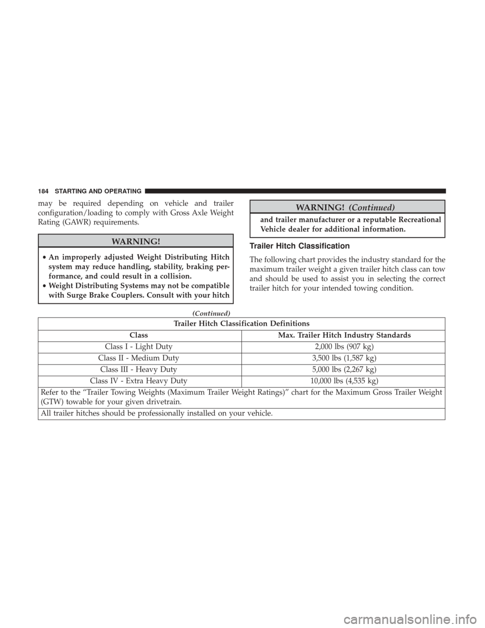
The following chart provides the industry standard for the
maximum trailer weight a given trailer hitch class can tow
and should be used to assist you in selecting the correct
trailer hitch for your intended towing condition.
Trailer Hitch Classification Definitions
Class Max. Trailer Hitch Industry Standards
Class I - Light Duty 2,000 lbs (907 kg)
Class II - Medium Duty 3,500 lbs (1,587 kg)
Class III - Heavy Duty 5,000 lbs (2,267 kg)
Class IV - Extra Heavy Duty 10,000 lbs (4,535 kg)
Refer to the “Trailer Towing Weights (Maximum Trailer Weight Ratings)” chart for the Maximum Gross Trailer Weight
(GTW) towable for your given drivetrain.
All trailer hitches should be professionally installed on your vehicle.
184 STARTING AND OPERATING
Page 190 of 347
CAUTION!
If the trailer weighs more than 1,000 lbs (453 kg)
loaded, it should have its own brakes and they should
be of adequate capacity. Failure to do this could lead to
accelerated brake lining wear, higher brake pedal
effort, and longer stopping distances.
Towing Requirements — Trailer Lights And Wiring
Whenever you pull a trailer, regardless of the trailer size,
stoplights and turn signals on the trailer are required for
motoring safety.
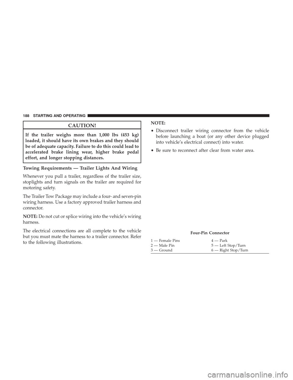
The Trailer Tow Package may include a four- and seven-pin
wiring harness. Use a factory approved trailer harness and
connector.
NOTE:Do not cut or splice wiring into the vehicle’s wiring
harness.
The electrical connections are all complete to the vehicle
but you must mate the harness to a trailer connector. Refer
to the following illustrations. NOTE:
•
Disconnect trailer wiring connector from the vehicle
before launching a boat (or any other device plugged
into vehicle’s electrical connect) into water.
• Be sure to reconnect after clear from water area.
Four-Pin Connector
1 — Female Pins 4 — Park
2 — Male Pin 5 — Left Stop/Turn
3 — Ground 6 — Right Stop/Turn
188 STARTING AND OPERATING
Page 195 of 347
Flowing/Rising Water
WARNING!
Do not drive on or across a road or path where water is
flowing and/or rising (as in storm run-off). Flowing
water can wear away the road or path’s surface and
cause your vehicle to sink into deeper water. Further-
more, flowing and/or rising water can carry your ve-
hicle away swiftly. Failure to follow this warning may
result in injuries that are serious or fatal to you, your
passengers, and others around you.
Shallow Standing Water
Although your vehicle is capable of driving through shal-
low standing water, consider the following Cautions and
Warnings before doing so.
WARNING!
•Driving through standing water limits your vehicle’s
traction capabilities. Do not exceed 5 mph (8 km/h)
when driving through standing water.
(Continued)
WARNING! (Continued)
•Driving through standing water limits your vehicle’s
braking capabilities, which increases stopping dis-
tances. Therefore, after driving through standing
water, drive slowly and lightly press on the brake
pedal several times to dry the brakes.
• Failure to follow these warnings may result in inju-
ries that are serious or fatal to you, your passengers,
and others around you.
CAUTION!
• Always check the depth of the standing water before
driving through it. Never drive through standing
water that is deeper than the bottom of the tire rims
mounted on the vehicle.
• Determine the condition of the road or the path that
is under water and if there are any obstacles in the
way before driving through the standing water.
• Do not exceed 5 mph (8 km/h) when driving through
standing water. This will minimize wave effects.
(Continued)
6
STARTING AND OPERATING 193
Page 200 of 347
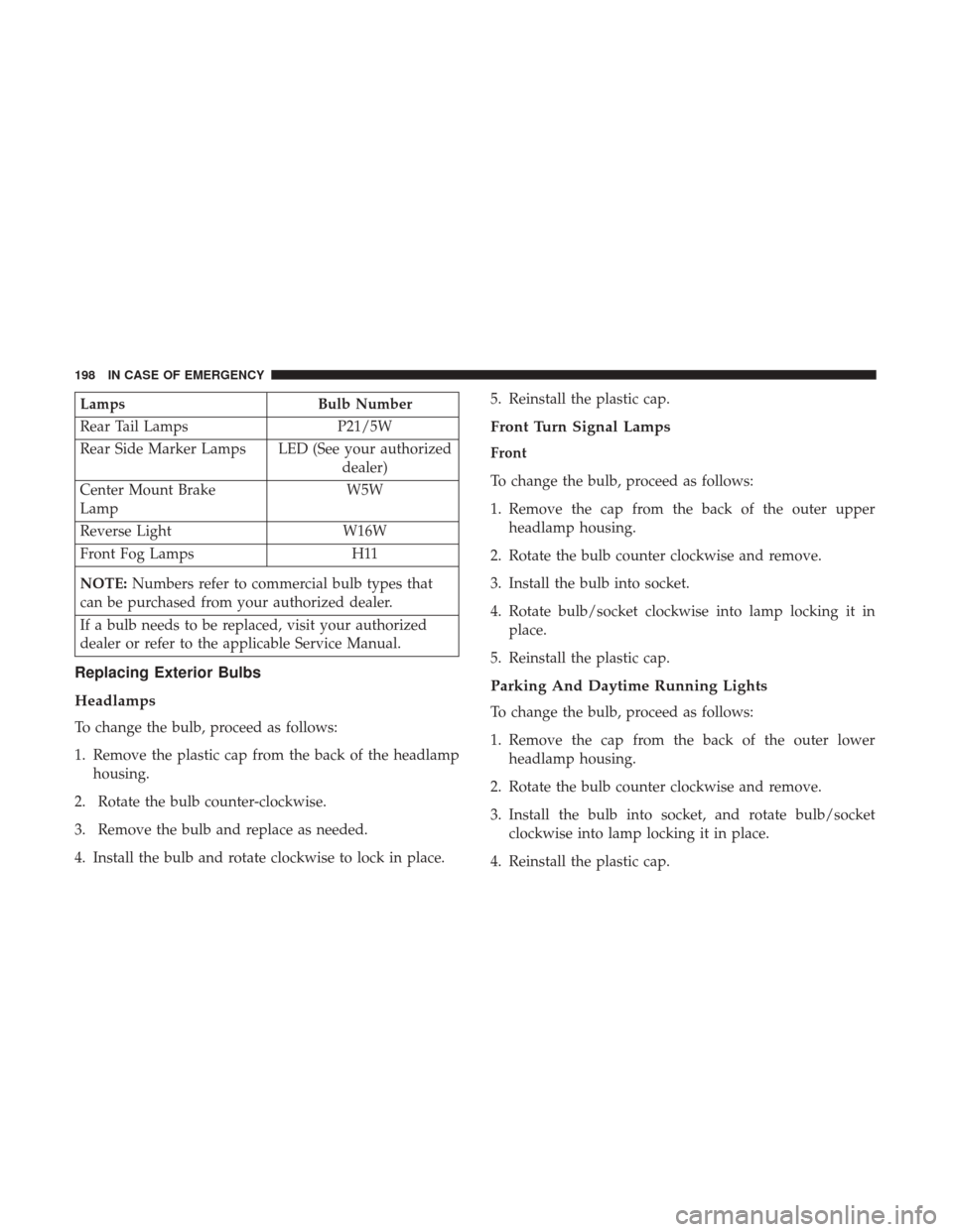
LampsBulb Number
Rear Tail Lamps P21/5W
Rear Side Marker Lamps LED (See your authorized dealer)
Center Mount Brake
Lamp W5W
Reverse Light W16W
Front Fog Lamps H11
NOTE: Numbers refer to commercial bulb types that
can be purchased from your authorized dealer.
If a bulb needs to be replaced, visit your authorized
dealer or refer to the applicable Service Manual.
Replacing Exterior Bulbs
Headlamps
To change the bulb, proceed as follows:
1. Remove the plastic cap from the back of the headlamp housing.
2. Rotate the bulb counter-clockwise.
3. Remove the bulb and replace as needed.
4. Install the bulb and rotate clockwise to lock in place. 5. Reinstall the plastic cap.
Front Turn Signal Lamps
Front
To change the bulb, proceed as follows:
1. Remove the cap from the back of the outer upper
headlamp housing.
2. Rotate the bulb counter clockwise and remove.
3. Install the bulb into socket.
4. Rotate bulb/socket clockwise into lamp locking it in place.
5. Reinstall the plastic cap.
Parking And Daytime Running Lights
To change the bulb, proceed as follows:
1. Remove the cap from the back of the outer lower headlamp housing.
2. Rotate the bulb counter clockwise and remove.
3. Install the bulb into socket, and rotate bulb/socket clockwise into lamp locking it in place.
4. Reinstall the plastic cap.
198 IN CASE OF EMERGENCY
Page 201 of 347
Front/Rear Side Marker Lamps
To change the bulb, proceed as follows:
The front/rear side marker lamps are LED and not ser-
viced separately. See your authorized dealer for replace-
ment of these lights.
Rear Tail, Stop, Backup And Turn Signal Lamps
The rear light clusters contain taillight, brake light, direc-
tion indicator and reverse/rear fog light bulbs. To access
the light clusters, proceed as follows:
1. Open the rear doors.
2. Remove the screws and remove the tail lamp assembly.
3. Remove the screws and separate the backplate from thelamp housing.
4. Remove the tail, stop, or turn signal bulbs by pushing them slightly and turning counter-clockwise.
5. Remove the backup lamp bulb by pulling straight out.
6. Replace lamps as required and reinstall lamp. The bulbs are arranged inside the light cluster as follows:
Third Brake Light (Center Mount)
To change the bulb, proceed as follows:
1. For versions with tailgate, loosen the two fastening
screws and extract the cluster.
2. For versions with swing doors, remove rubber plugs, remove retaining tabs and extract the cluster.
3. For versions with high roof and swing doors, remove the pressure-fit plastic guard and rubber cap using a
screwdriver, release the retaining tags as shown in the
figure and remove the unit.
4. Remove the appropriate tabs and remove the bulb holder.
5. Remove the snap-fitted bulb and replace it.
License Plate Lights
Proceed as follows to replace the bulbs:
1. Disengage the holding tabs and remove the lens by lifting to the left.
7
IN CASE OF EMERGENCY 199