ECO mode Ram ProMaster City 2018 User Guide
[x] Cancel search | Manufacturer: RAM, Model Year: 2018, Model line: ProMaster City, Model: Ram ProMaster City 2018Pages: 180, PDF Size: 7.52 MB
Page 1 of 180

18VM-926-AA
RAM ProMaster CITYFirst EditionUser GUIDE
RAMTRUCKS.COM (U.S.) ramtrucks.ca (CANADA)
©2017 FCA US LLC. All Rights Reserved. RAM is a registered trademark of FCA US LLC.
DOWNLOAD A FREE ELECTRONIC COPY OF
THE MOST UP-TO-DATE OWNER’S MANUAL, MEDIA
AND WARRANTY BOOKLET BY VISITING:
WWW.MOPAR.COM/EN-US/CARE/OWNERS-MANUAL.HTML (U.S. RESIDENts); WWW.OWNERS.MOPAR.CA (CANADIAN RESIDENts).
WHETHER IT’S PROVIDING INFORMATION
ABOUT SPECIFIC PRODUCT FEATURES,
TAKING A TOUR THROUGH YOUR VEHICLE’S HERITAGE, KNOWING WHAT STEPS TO
TAKE FOLLOWING AN ACCIDENT, OR SCHEDULING YOUR NEXT APPOINTMENT, WE KNOW YOU’LL FIND THE APP AN IMPORTANT EXTENSION OF YOUR RAM VEHICLE. SIMPLY
DOWNLOAD THE APP, SELECT YOUR MAKE AND MODEL
AND ENJOY THE RIDE. TO GET THIS APP, GO DIRECTLY TO
THE APP STORE OR GOOGLE PLAY AND ENTER THE SEARCH KEYWORD “RAM TOOLBOX” (U.S. residents ONLY).
WWW.RAMTRUCKS.COM/EN/OWNERS (U.S.) or
WWW.OWNERS.MOPAR.CA (CANADA) PROVIDES SPECIAL OFFERS TAILORED TO YOUR NEEDS, CUSTOMIZED VEHICLE GALLERIES, PERSONALIZED SERVICE RECORDS AND MORE.
TO GET THIS INFORMATION, JUST CREATE AN ACCOUNT AND CHECK BACK OFTEN.
Get warranty and other information online – you
can review and print or download a copy of the
owner’s manual, navigation/uconnect manuals
and the limited warranties provided by FCA US LLC for your vehicle by visiting www.mopar.com (U.S.)
or WWW.OWNERS.MOPAR.CA (CANADA). Click on the
applicable link in the “popular topics” area of the
www.mopar.com (U.S.) or WWW.OWNERS.MOPAR.CA (CANADA) homepage and follow the instructions
to select the applicable year, make and model of your vehicle.
2018
RAM
PROMASTER CITY
USER
GUIDE
Page 2 of 180

This guide has been prepared to help you get quickly acquainted with your new RAM brand vehicle
and to provide a convenient reference source for common questions. Howev\
er, it is not a substitute for your Owner’s Manual.
For complete operational instructions, maintenance procedures and import\
ant safety messages, please consult your Owner’s Manual, Navigation/Uconnect manuals found on the website on the back c\
over and
other Warning Labels in your vehicle.
Not all features shown in this guide may apply to your vehicle. For addi\
tional information on accessories
to help personalize your vehicle, visit www.mopar.com (U.S.), www.mopar.ca (Canada) or your local
RAM brand dealer.
DRIVING AND ALCOHOL
Drunken driving is one of the most frequent causes of collisions. Your driving ability can
be seriously impaired with blood alcohol levels far below the legal mini\
mum. If you are drinking, don’t
drive. Ride with a designated non-drinking driver, call a cab, a friend, or use public transportation.
WARNING
Driving after drinking can lead to a collision. Your perceptions are less sharp, your reflexes are slower,
and your judgment is impaired when you have been drinking. Never drink a\
nd then drive.
IMPORTANT
Get warranty and other information online – you can review and print \
or download a copy of the Owner’s Manual, Navigation/Uconnect manuals and the limited warranties provided by FCA US LLC for your
vehicle by visiting www.mopar.com (U.S.) or www.owners.mopar.ca (Canada). Click on the applicable
link in the “Popular Topics” area of the www.mopar.com (U.S.) or www.owners.mopar.ca (Canada)
homepage and follow the instructions to select the applicable year, make and model of your vehicle.
This User Guide is intended to familiarize you with the important featur\
es of your vehicle. Your Owner’s Manual, Navigation/Uconnect manuals and Warranty Booklet can be found by visiting the website on the
back cover of your User Guide. We hope you find these resources useful. U.S. residents can purchase
replacement kits by visiting www.techauthority.com and Canadian residents can purchase replacement
kits by calling 1 800 387-1143.
The driver’s primary responsibility is the safe operation of the vehicle. Driving while distracted can result in loss of vehicle control, resulting in a collision and personal injury. FCA US LLC strongly recommends that the
driver use extreme caution when using any device or feature that may tak\
e their attention off the road. Use of
any electrical devices, such as cellular telephones, computers, portable\
radios, vehicle navigation or other devices, by the driver while the vehicle is moving is dangerous and coul\
d lead to a serious collision. Texting while driving is also dangerous and should never be done while the vehic\
le is moving. If you find yourself
unable to devote your full attention to vehicle operation, pull off the \
road to a safe location and stop your
vehicle. Some states or provinces prohibit the use of cellular telephone\
s or texting while driving. It is always the driver’s responsibility to comply with all local laws.
Page 20 of 180
INTERIOR LIGHTS
The map lights and dome lights are mounted
between the sun visors on the overhead con-
sole. Each light is turned on by pushing the
corresponding switch.
In auto-mode, the passenger and cargo area
lights will come on automatically when you
open the sliding doors and the rear wing
doors. The lights turn off when you close the
doors.
The lights will fade to off after approximately
30 seconds, or they will immediately fade to
off once the ignition switch is turned to
ON/RUN from the OFF position.
WIPERS AND WASHERS
The windshield wiper/washer lever is located
on the right side of the steering column.
NOTE:
The windshield wipers/washers will only op-
erate with the ignition in the ON/RUN posi-
tion.
Front Wiper Operation
There are five different modes of operation
for the front windshield wipers. The wind-
shield wiper lever can be moved in several
positions to access these modes.
Windshield Wiper Off
This is the normal position of the wiper lever: O.
Low Speed
Rotate the end of the lever upward to the
second detent. The wipers will operate at low
speed.
High Speed
Rotate the end of the lever upward to the
third detent. The wipers will operate at high
speed.
Intermittent Wiper System
Rotate the end of the lever upward to the first
detent. The wipers will operate at intermit-
tent speed. When the vehicle's speed in-
creases, the time between the wipes will
decrease.
Windshield Washers
Pull the windshield wiper/washer lever to-
ward the steering wheel to activate the wash-
ers. The wipers will activate automatically for
three cycles after the lever is released.
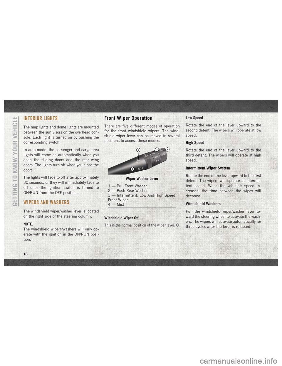
Wiper Washer Lever
1 — Pull Front Washer
2 — Push Rear Washer
3 — Intermittent, Low And High Speed
Front Wiper
4 — Mist
GETTING TO KNOW YOUR VEHICLE
18
Page 21 of 180
CAUTION!
• Turn the windshield wipers off whendriving through an automatic car wash.
Damage to the windshield wipers may
result if the wiper control is left in any
position other than off.
• In cold weather, always turn off the wiper
switch and allow the wipers to return to
the park position before turning off the
engine. If the wiper switch is left on and
the wipers freeze to the windshield,
damage to the wiper motor may occur
when the vehicle is restarted.
• Always remove any buildup of snow that
prevents the windshield wiper blades
from returning to the off position. If the
windshield wiper control is turned off
and the blades cannot return to the off
position, damage to the wiper motor may
occur.
Manual High Speed/Mist
Push the lever upward from the off position.
The wipers will operate at high speed to clear
off road mist or spray from a passing vehicle.
This operation will continue until the lever is
released. When the lever is released, the
wipers will return to the off position and
automatically shut off.
Rear Wiper Operation
Rear Windshield Wiper Operation
Rotate the windshield wiper lever center ring
upwards to operate the rear window wiper as
follows:
• In intermittent mode when the front win-
dow wiper is not operating.
• In synchronous mode (at half the speed of the front window wiper) when the front
window wiper is operating. • In continuous mode while vehicle is in
REVERSE.
With the windshield wipers on, and REVERSE
gear engaged, rear window wiping will be
continuous in the same way.
Rear Windshield Washer Operation
Pushing the windshield wiper lever forward
activates the rear window washer. Keep the
windshield wiper lever pushed for more than
quarter a second to activate the rear window
wiper as well. Releasing the windshield wiper
lever will activate the smart washing func-
tion, as described for the windshield wipers.
The function stops when the windshield
wiper lever is released.
19
Page 23 of 180
Manual Climate Control Descriptions
IconDescription
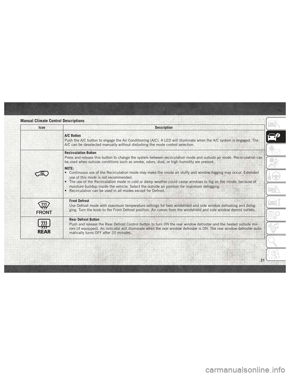
A/C Button
Push the A/C button to engage the Air Conditioning (A/C). A LED will illuminate when the A/C system is engaged. The
A/C can be deselected manually without disturbing the mode control selection.
Recirculation Button
Press and release this button to change the system between recirculation mode and outside air mode. Recirculation can
be used when outside conditions such as smoke, odors, dust, or high humidity are present.
NOTE:
• Continuous use of the Recirculation mode may make the inside air stuffy and window fogging may occur. Extended
use of this mode is not recommended.
• The use of the Recirculation mode in cold or damp weather could cause windows to fog on the inside, because of
moisture buildup inside the vehicle. Select the outside air position for maximum defogging.
• Recirculation can be used in all modes except for Defrost.
Front Defrost
Use Defrost mode with maximum temperature settings for best windshield and side window defrosting and defog-
ging. Turn the knob to the Front Defrost position. Air comes from the windshield and side window demist outlets.
Rear Defrost Button
Push and release the Rear Defrost Control button to turn ON the rear window defroster and the heated outside mir-
rors (if equipped). An indicator will illuminate when the rear window defroster is ON. The rear window defroster auto-
matically turns OFF after 20 minutes.
21
Page 25 of 180
IconDescription
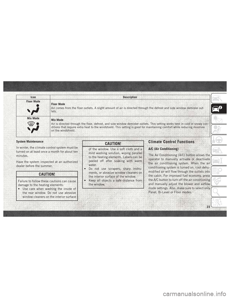
Floor Mode
Floor Mode
Air comes from the floor outlets. A slight amount of air is directed through the defrost and side window demister out-
lets.
Mix Mode
Mix Mode
Air is directed through the floor, defrost, and side window demister outlets. This setting works best in cold or snowy con-
ditions that require extra heat to the windshield. This setting is good for maintaining comfort while reducing moisture
on the windshield.
System Maintenance
In winter, the climate control system must be
turned on at least once a month for about ten
minutes.
Have the system inspected at an authorized
dealer before the summer.
CAUTION!
Failure to follow these cautions can cause
damage to the heating elements:
• Use care when washing the inside of the rear window. Do not use abrasive
window cleaners on the interior surface
CAUTION!
of the window. Use a soft cloth and a
mild washing solution, wiping parallel
to the heating elements. Labels can be
peeled off after soaking with warm
water.
• Do not use scrapers, sharp instru-
ments, or abrasive window cleaners on
the interior surface of the window.
• Keep all objects a safe distance from
the window.
Climate Control Functions
A/C (Air Conditioning)
The Air Conditioning (A/C) button allows the
operator to manually activate or deactivate
the air conditioning system. When the air
conditioning system is turned on, cool dehu-
midified air will flow through the outlets into
the cabin. For improved fuel economy, press
the A/C button to turn off the air conditioning
and manually adjust the blower and airflow
mode settings. Also, make sure to select only
Panel, Bi-Level or Floor modes.
23
Page 26 of 180
NOTE:
• If fog or mist appears on the windshield orside glass, select Defrost mode and in-
crease blower speed if needed.
• If your air conditioning performance seems lower than expected, check the front of the
A/C condenser (located in front of the ra-
diator), for an accumulation of dirt or in-
sects. Clean with a gentle water spray from
the front of the radiator and through the
condenser.
Recirculation
When outside air contains smoke, odors, or
high humidity, or if rapid cooling is desired,
you may wish to recirculate interior air by
pressing the Recirculation control button.
The recirculation indicator will illuminate
when this button is selected. Press the but-
ton a second time to turn off the Recircula-
tion mode and allow outside air into the
vehicle. NOTE:
In cold weather, use of recirculation mode
may lead to excessive window fogging. On
systems with Manual Climate Controls, the
Recirculation mode is not allowed in Defrost
mode to improve window clearing operation.
Recirculation will be disabled automatically
if this mode is selected. Attempting to use
Recirculation while in this mode will cause
the LED in the control button to blink and
then turn off.
Operating Tips
Summer Operation
The engine cooling system must be protected
with a high-quality antifreeze coolant to pro-
vide proper corrosion protection and to pro-
tect against engine overheating. OAT coolant
(conforming to MS.90032) is recommended.
Refer to “Dealer Service” in “Servicing And
Maintenance” in your Owner’s Manual at
www.mopar.com/en-us/care/owners-manual.html
(U.S. Residents) or www.owners.mopar.ca
(Canadian Residents) for proper coolant se-
lection.
Winter Operation
To ensure the best possible heater and de-
froster performance, make sure the engine
cooling system is functioning properly and
the proper amount, type, and concentration
of coolant is used. Refer to “Dealer Service”
in “Servicing And Maintenance” in your Own-
er’s Manual at
www.mopar.com/en-us/
care/owners-manual.html
(U.S. Residents) or
www.owners.mopar.ca (Canadian Residents)
for proper coolant selection. Use of the air
Recirculation mode during Winter months is
not recommended because it may cause win-
dow fogging.
Vacation/Storage
Any time you store your vehicle or keep it out
of service (i.e., vacation) for two weeks or
more, run the air conditioning system at idle
for about five minutes in fresh air with the
blower setting on high. This will ensure ad-
equate system lubrication to minimize the
possibility of compressor damage when the
system is started again.
GETTING TO KNOW YOUR VEHICLE
24
Page 32 of 180
INSTRUMENT CLUSTER DISPLAY
Your vehicle may be equipped with an instru-
ment cluster display, which offers useful in-
formation to the driver. With the ignition in
the STOP/OFF mode, opening/closing of a
door will activate the display for viewing, and
display the total miles, or kilometers, in the
odometer. Your instrument cluster display is
designed to display important information
about your vehicle’s systems and features.
Using a driver interactive display located on
the instrument panel, your instrument clus-
ter display can show you how systems are
working and give you warnings when they are
not. The steering wheel mounted controls
allow you to scroll through the main menus
and submenus. You can access the specific
information you want and make selections
and adjustments.
Location And Controls
The instrument cluster display features a
driver-interactive display that is located in
the instrument cluster.The menu items described below are an ex-
ample of what can be found in the vehicle's
menu:
• Dimmer
• Speed Beep
• Trip B
• Set Time
• Set Date
• Autoclose
• Units
• Language
• Buzzer Volume
• Belt Buzzer
• Day Lights
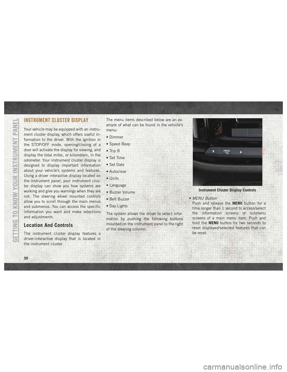
The system allows the driver to select infor-
mation by pushing the following buttons
mounted on the instrument panel to the right
of the steering column:
•
MENU Button
Push and release the MENUbutton for a
time longer than 1 second to access/select
the information screens or submenu
screens of a main menu item. Push and
hold the MENUbutton for two seconds to
reset displayed/selected features that can
be reset.
Instrument Cluster Display Controls
GETTING TO KNOW YOUR INSTRUMENT PANEL
30
Page 55 of 180
WARNING!
used to install rear-facing or forward-
facing child restraints that have a har-
ness for restraining the child.
Supplemental Restraint Systems
(SRS)
Some of the safety features described in this
section may be standard equipment on some
models, or may be optional equipment on
others. If you are not sure, ask your autho-
rized dealer.
The air bag system must be ready to protect
you in a collision. The Occupant Restraint
Controller (ORC) monitors the internal cir-
cuits and interconnecting wiring associated
with the electrical Air Bag System Compo-
nents. Your vehicle may be equipped with the
following Air Bag System Components:
Air Bag System Components
• Occupant Restraint Controller (ORC)
• Air Bag Warning Light
• Steering Wheel and Column• Instrument Panel
• Knee Impact Bolsters
• Driver and Front Passenger Air Bags
• Seat Belt Buckle Switch
• Supplemental Side Air Bags
• Supplemental Knee Air Bags
• Front and Side Impact Sensors
• Seat Belt Pretensioners
Air Bag Warning Light
The ORC monitors the readiness of the
electronic parts of the air bag system when-
ever the ignition switch is in the AVV/START
or MAR/ACC/ON/RUN position. If the ignition
switch is in the STOP/OFF/LOCK position the
air bag system is not on and the air bags will
not inflate.
The ORC contains a backup power supply
system that may deploy the air bag system
even if the battery loses power or it becomes
disconnected prior to deployment.
The ORC turns on the Air Bag Warning Light
in the instrument panel for approximately
four to eight seconds for a self-check when the ignition switch is in the MAR/ACC/ON/
RUN position. After the self-check, the Air
Bag Warning Light will turn off. If the ORC
detects a malfunction in any part of the
system, it turns on the Air Bag Warning Light,
either momentarily or continuously. A single
chime will sound to alert you if the light
comes on again after initial startup.
The ORC also includes diagnostics that will
illuminate the instrument panel Air Bag
Warning Light if a malfunction is detected
that could affect the air bag system. The
diagnostics also record the nature of the
malfunction. While the air bag system is
designed to be maintenance free, if any of the
following occurs, have an authorized dealer
service the air bag system immediately.
• The Air Bag Warning Light does not come
on during the four to eight seconds when
the ignition switch is first in the MAR/ACC/
ON/RUN position.
• The Air Bag Warning Light remains on after the four to eight-second interval.
• The Air Bag Warning Light comes on inter- mittently or remains on while driving.
53
Page 71 of 180
WARNING!
for attaching other items or equipment
to the vehicle.
Installing Child Restraints Using The Ve-
hicle Seat Belt In Vehicles With Rear Seat-
ing
Child restraint systems are designed to be
secured in vehicle seats by lap belts or the lap
belt portion of a lap/shoulder belt.
WARNING!
• Improper installation or failure to prop-erly secure a child restraint can lead to
failure of the restraint. The child could
be badly injured or killed.
WARNING!
• Follow the child restraint manufacturer’sdirections exactly when installing an in-
fant or child restraint.
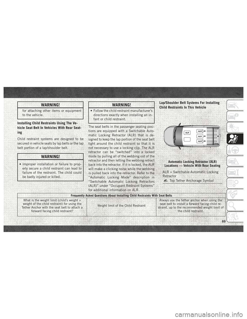
The seat belts in the passenger seating posi-
tions are equipped with a Switchable Auto-
matic Locking Retractor (ALR) that is de-
signed to keep the lap portion of the seat belt
tight around the child restraint so that it is
not necessary to use a locking clip. The ALR
retractor can be “switched” into a locked
mode by pulling all of the webbing out of the
retractor and then letting the webbing retract
back into the retractor. If it is locked, the ALR
will make a clicking noise while the webbing
is pulled back into the retractor. Refer to the
“Automatic Locking Mode” description in
“Switchable Automatic Locking Retractors
(ALR)” under “Occupant Restraint Systems”
for additional information on ALR.
Lap/Shoulder Belt Systems For Installing
Child Restraints In This Vehicle
Frequently Asked Questions About Installing Child Restraints With Seat Belts
What is the weight limit (child’s weight +
weight of the child restraint) for using the
Tether Anchor with the seat belt to attach a forward facing child restraint? Weight limit of the Child RestraintAlways use the tether anchor when using the
seat belt to install a forward facing child re-
straint, up to the recommended weight limit of the child restraint.
Automatic Locking Retractor (ALR)
Locations — Vehicle With Rear Seating
ALR = Switchable Automatic Locking
Retractor
Top Tether Anchorage Symbol
69