tire size Ram ProMaster City 2018 User Guide
[x] Cancel search | Manufacturer: RAM, Model Year: 2018, Model line: ProMaster City, Model: Ram ProMaster City 2018Pages: 180, PDF Size: 7.52 MB
Page 37 of 180
— Tire Pressure Monitoring System
(TPMS) Warning Light
The warning light switches on and a message
is displayed to indicate that the tire pressure
is lower than the recommended value and/or
that slow pressure loss is occurring. In these
cases, optimal tire duration and fuel con-
sumption may not be guaranteed.
Should one or more tires be in the condition
mentioned above, the display will show the
indications corresponding to each tire in
sequence.
CAUTION!
Do not continue driving with one or more
flat tires as handling may be compro-
mised. Stop the vehicle, avoiding sharp
braking and steering. If a tire puncture
occurs, repair immediately using the dedi-
cated tire repair kit and contact your au-
thorized dealer as soon as possible.
Each tire, including the spare (if provided),
should be checked monthly when cold and
inflated to the inflation pressure recom-
mended by the vehicle manufacturer on the vehicle placard or tire inflation pressure la-
bel. (If your vehicle has tires of a different
size than the size indicated on the vehicle
placard or tire inflation pressure label, you
should determine the proper tire inflation
pressure for those tires.)
As an added safety feature, your vehicle has
been equipped with a tire pressure monitor-
ing system (TPMS) that illuminates a low tire
pressure telltale when one or more of your
tires is significantly under-inflated. Accord-
ingly, when the low tire pressure telltale illu-
minates, you should stop and check your tires
as soon as possible, and inflate them to the
proper pressure. Driving on a significantly
under-inflated tire causes the tire to overheat
and can lead to tire failure. Under-inflation
also reduces fuel efficiency and tire tread
life, and may affect the vehicle’s handling
and stopping ability.
Please note that the TPMS is not a substitute
for proper tire maintenance, and it is the
driver’s responsibility to maintain correct tire
pressure, even if under-inflation has not
reached the level to trigger illumination of the
TPMS low tire pressure telltale.Your vehicle has also been equipped with a
TPMS malfunction indicator to indicate when
the system is not operating properly. The
TPMS malfunction indicator is combined
with the low tire pressure telltale. When the
system detects a malfunction, the telltale will
flash for approximately one minute and then
remain continuously illuminated. This se-
quence will continue upon subsequent ve-
hicle start-ups as long as the malfunction
exists. When the malfunction indicator is
illuminated, the system may not be able to
detect or signal low tire pressure as intended.
TPMS malfunctions may occur for a variety of
reasons, including the installation of replace-
ment or alternate tires or wheels on the ve-
hicle that prevent the TPMS from functioning
properly. Always check the TPMS malfunc-
tion telltale after replacing one or more tires
or wheels on your vehicle to ensure that the
replacement or alternate tires and wheels
allow the TPMS to continue to function
properly.
35
Page 38 of 180
CAUTION!
The TPMS has been optimized for the
original equipment tires and wheels.
TPMS pressures and warning have been
established for the tire size equipped on
your vehicle. Undesirable system opera-
tion or sensor damage may result when
using replacement equipment that is not
of the same size, type, and/or style. After-
market wheels can cause sensor damage.
Using aftermarket tire sealants may cause
the Tire Pressure Monitoring System
(TPMS) sensor to become inoperable. Af-
ter using an aftermarket tire sealant it is
recommended that you take your vehicle
to your authorized dealer to have your
sensor function checked.
— Vehicle Security Warning Light
This telltale will illuminate when the vehicle
security alarm system has detected an at-
tempt was made to break into the vehicle.
— Engine Check/Malfunction Indica-
tor Warning Light (MIL)
The Engine Check/Malfunction Indicator
Light (MIL) is a part of an Onboard Diagnostic
System called OBD II that monitors engine
and automatic transmission control systems.
The light will illuminate when the ignition is
in the ON/RUN position before engine start.
If the bulb does not come on when turning
the key from OFF to ON/RUN, have the con-
dition checked promptly.
Certain conditions, such as a loose or missing
gas cap, poor quality fuel, etc., may illumi-
nate the light after engine start. The vehicle
should be serviced if the light stays on
through several typical driving styles. In most
situations, the vehicle will drive normally and
will not require towing.
When the engine is running, the MIL may
flash to alert serious conditions that could
lead to immediate loss of power or severe
catalytic converter damage. The vehicle
should be serviced as soon as possible if this
occurs.
WARNING!
A malfunctioning catalytic converter, as
referenced above, can reach higher tem-
peratures than in normal operating condi-
tions. This can cause a fire if you drive
slowly or park over flammable substances
such as dry plants, wood, cardboard, etc.
This could result in death or serious injury
to the driver, occupants or others.
CAUTION!
Prolonged driving with the Malfunction
Indicator Light (MIL) on could cause dam-
age to the vehicle control system. It also
could affect fuel economy and driveability.
If the MIL is flashing, severe catalytic
converter damage and power loss will soon
occur. Immediate service is required.
GETTING TO KNOW YOUR INSTRUMENT PANEL
36
Page 45 of 180
CAUTION!
• The TPMS has been optimized for theoriginal equipment tires and wheels.
TPMS pressures and warning have been
established for the tire size equipped on
your vehicle. Undesirable system opera-
tion or sensor damage may result when
using replacement equipment that is not
of the same size, type, and/or style.
Aftermarket wheels can cause sensor
damage.
• Using aftermarket tire sealants may
cause the Tire Pressure Monitoring Sys-
tem (TPMS) sensor to become inoper-
able. After using an aftermarket tire
sealant it is recommended that you take
your vehicle to an authorized dealership
to have your sensor function checked.
• After inspecting or adjusting the tire
pressure always reinstall the valve stem
cap. This will prevent moisture and dirt
from entering the valve stem, which
could damage the TPMS sensor. NOTE:
• The TPMS is not intended to replace nor-
mal tire care and maintenance or to provide
warning of a tire failure or condition.
• The TPMS should not be used as a tire pressure gauge while adjusting your tire
pressure.
• Driving on a significantly under-inflated tire causes the tire to overheat and can lead to
tire failure. Under-inflation also reduces
fuel efficiency and tire tread life, and may
affect the vehicle’s handling and stopping
ability.
• The TPMS is not a substitute for proper tire maintenance, and it is the driver’s respon-
sibility to maintain correct tire pressure
using an accurate tire pressure gauge, even
if under-inflation has not reached the level
to trigger illumination of the TPM Telltale
Light.
• Seasonal temperature changes will affect tire pressure, and the TPMS will monitor
the actual tire pressure in the tire.
Base System
This is the TPMS warning indicator
located in the instrument cluster.
The TPMS uses wireless technology
with wheel rim mounted electronic sensors to
monitor tire pressure levels. Sensors,
mounted to each wheel as part of the valve
stem, transmit tire pressure readings to the
Receiver Module.
NOTE:
It is particularly important for you to check
the tire pressure in all of the tires on your
vehicle regularly and to maintain the proper
pressure.
The TPMS consists of the following compo-
nents:
• Receiver Module.
• Four Tire Pressure Monitoring Sensors.
• Tire Pressure Monitoring Telltale Light.
43
Page 46 of 180
Tire Pressure Monitoring Low Pressure
Warnings
The Tire Pressure Monitoring Telltale Light
will illuminate in the instrument cluster, an
audible chime will be activated, and the
“Check tire pressure” text message will dis-
play when one or more of the four active road
tire pressures are low. Should this occur, you
should stop as soon as possible, check the
inflation pressure of each tire on your vehicle,
and inflate each tire to the vehicle’s recom-
mended cold placard pressure value. The
system will automatically update and the Tire
Pressure Monitoring Light will extinguish
once the updated tire pressures have been
received. The vehicle may need to be driven
for up to 20 minutes above 15 mph
(24 km/h) to receive this information.
Check TPMS Warnings
The Tire Pressure Monitoring Telltale Light
will flash on and off for 75 seconds and
remain on solid when a system fault is de-
tected, an audible chime will be activated
and a proper text message will be displayed.
If the ignition key is cycled, this sequence
will repeat providing the system fault stillexists. The Tire Pressure Monitoring Telltale
Light will turn off when the fault condition no
longer exists. A system fault can occur with
any of the following scenarios:
1. Jamming due to electronic devices or driv-
ing next to facilities emitting the same
radio frequencies as the TPM sensors.
2. Installing some form of aftermarket win- dow tinting that affects radio wave
signals.
3. Snow or ice around the wheels or wheel housings.
4. Using tire chains on the vehicle.
5. Using wheels/tires not equipped with TPM sensors.
NOTE:
Your vehicle can be equipped with either Tire
Service Kit, compact spare tire or regular size
spare tire (with or without original TPMS
sensor).
1. Tire Service Kit (original tire sealant – if equipped): After fixing the punctured tire
with original tire sealant, the original situ-
ation will be restored, so system will turn
off the telltale during the normal drive. 2. Compact Spare Tire – if equipped: The
compact spare wheel is not equipped with
TPMS sensor. So when mounted, during
the normal drive the system will turn on
the telltale (flashing for approximately
75 sec. then remains solid). This condi-
tion persists until a wheel equipped with
original TPMS sensor has been mounted
on the vehicle.
3. Regular size spare tire (not equipped with TPMS sensor): When mounted, during the
normal drive the system will turn on the
telltale (flashing for approximately
75 sec. then remains solid). This condi-
tion persists until a wheel equipped with
original TPMS sensor has been mounted
on the vehicle. Then the system will be
restored and the telltale will turn off dur-
ing the normal drive.
4. Regular size spare tire (equipped with TPMS sensor): When mounted, the tell-
tale will turn off during the normal drive.
5. In all the above cases please check the replacement tire inflation pressure before
driving your vehicle.
SAFETY
44
Page 117 of 180

RAISING THE VEHICLE
In the case where it is necessary to raise the
vehicle, go to an authorized dealer or service
station.
TIRES
Tire Safety Information
Tire safety information will cover aspects of
the following information: Tire Markings, Tire
Identification Numbers, Tire Terminology and
Definitions, Tire Pressures, and Tire Loading.
Tire Markings
NOTE:
• P (Passenger) — Metric tire sizing is basedon U.S. design standards. P-Metric tires
have the letter “P” molded into the sidewall
preceding the size designation. Example:
P215/65R15 95H. •
European — Metric tire sizing is based on
European design standards. Tires designed to
this standard have the tire size molded into
the sidewall beginning with the section width.
The letter "P" is absent from this tire size
designation. Example: 215/65R15 96H.
• LT (Light Truck) — Metric tire sizing is
based on U.S. design standards. The size
designation for LT-Metric tires is the same
as for P-Metric tires except for the letters
“LT” that are molded into the sidewall pre-
ceding the size designation. Example:
LT235/85R16.
• Temporary spare tires are designed for tem- porary emergency use only. Temporary high
pressure compact spare tires have the letter
“T” or “S” molded into the sidewall preced-
ing the size designation. Example: T145/
80D18 103M.
• High flotation tire sizing is based on U.S. design standards and it begins with the tire
diameter molded into the sidewall. Ex-
ample: 31x10.5 R15 LT.
Tire Markings
1 — U.S. DOT
Safety Stan-
dards Code
(TIN) 4 — Maximum
Load
2 — Size Desig-
nation 5 — Maximum
Pressure
3 — Service
Description 6 — Treadwear,
Traction and
Temperature
Grades
115
Page 118 of 180

Tire Sizing Chart
EXAMPLE:
Example Size Designation: P215/65R15XL 95H, 215/65R15 96H, LT235/85R16C, T145/80D18 103M, 31x10.5 R15 LT
P = Passenger car tire size based on U.S. design standards, or
"....blank...." = Passenger car tire based on European design standards, or
LT = Light truck tire based on U.S. design standards, or
TorS= Temporary spare tire or
31 = Overall diameter in inches (in)
215, 235, 145 = Section width in millimeters (mm)
65, 85, 80 = Aspect ratio in percent (%)
• Ratio of section height to section width of tire, or
10.5 = Section width in inches (in)
R = Construction code
• "R" means radial construction, or
• "D" means diagonal or bias construction
15, 16, 18 = Rim diameter in inches (in)
SERVICING AND MAINTENANCE
116
Page 120 of 180

Tire Identification Number (TIN)
The TIN may be found on one or both sides of
the tire; however, the date code may only be
on one side. Tires with white sidewalls will
have the full TIN, including the date code,
located on the white sidewall side of the tire.
Look for the TIN on the outboard side of black
sidewall tires as mounted on the vehicle. If
the TIN is not found on the outboard side,
then you will find it on the inboard side of the
tire.
EXAMPLE:
DOT MA L9 ABCD 0301
DOT = Department of Transportation
• This symbol certifies that the tire is in compliance with the U.S. Department of Transportation tire safety standards and is approved for highway
use
MA = Code representing the tire manufacturing location (two digits)
L9 = Code representing the tire size (two digits)
ABCD = Code used by the tire manufacturer (one to four digits)
03 = Number representing the week in which the tire was manufactured (two digits)
• 03 means the 3rd week
01 = Number representing the year in which the tire was manufactured (two digits)
• 01 means the year 2001
• Prior to July 2000, tire manufacturers were only required to have one number to represent the year in which the tire was manufactured. Example:
031 could represent the 3rd week of 1981 or 1991
SERVICING AND MAINTENANCE
118
Page 121 of 180
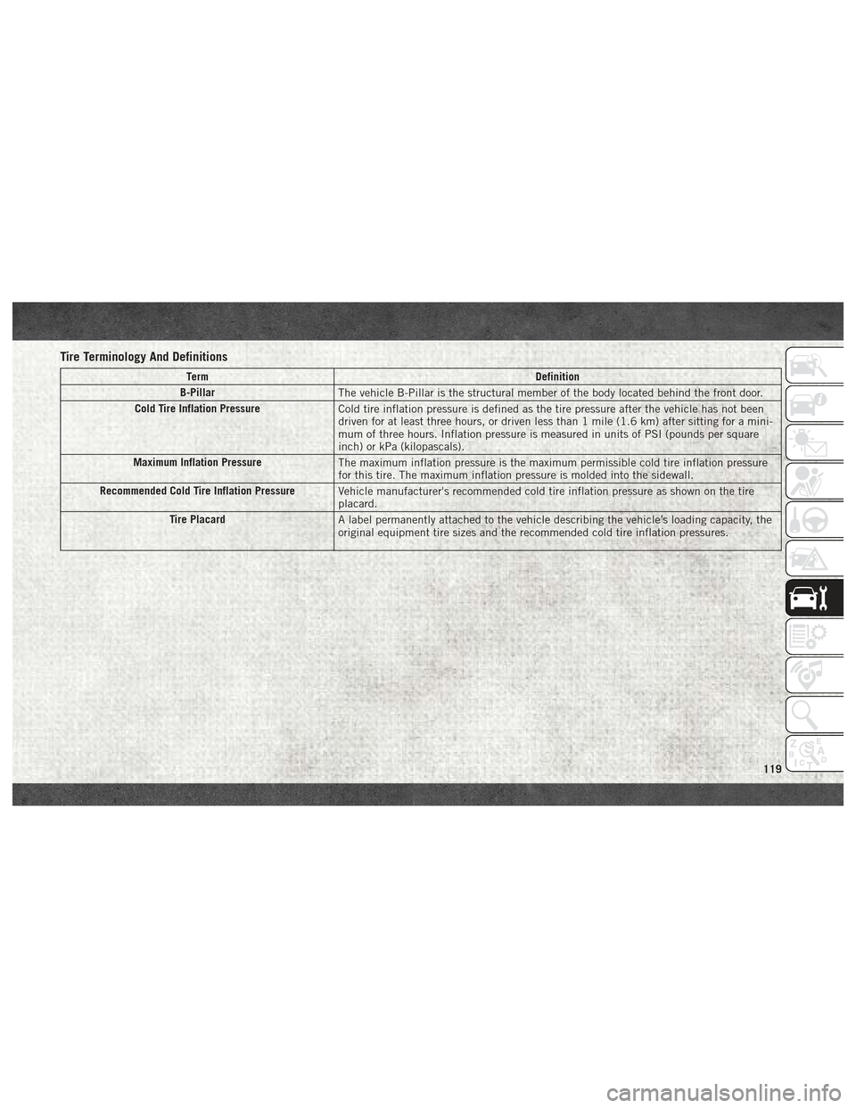
Tire Terminology And Definitions
TermDefinition
B-Pillar The vehicle B-Pillar is the structural member of the body located behind the front door.
Cold Tire Inflation Pressure Cold tire inflation pressure is defined as the tire pressure after the vehicle has not been
driven for at least three hours, or driven less than 1 mile (1.6 km) after sitting for a mini-
mum of three hours. Inflation pressure is measured in units of PSI (pounds per square
inch) or kPa (kilopascals).
Maximum Inflation Pressure The maximum inflation pressure is the maximum permissible cold tire inflation pressure
for this tire. The maximum inflation pressure is molded into the sidewall.
Recommended Cold Tire Inflation Pressure Vehicle manufacturer's recommended cold tire inflation pressure as shown on the tire
placard.
Tire Placard A label permanently attached to the vehicle describing the vehicle’s loading capacity, the
original equipment tire sizes and the recommended cold tire inflation pressures.
119
Page 122 of 180
Tire Loading And Tire Pressure
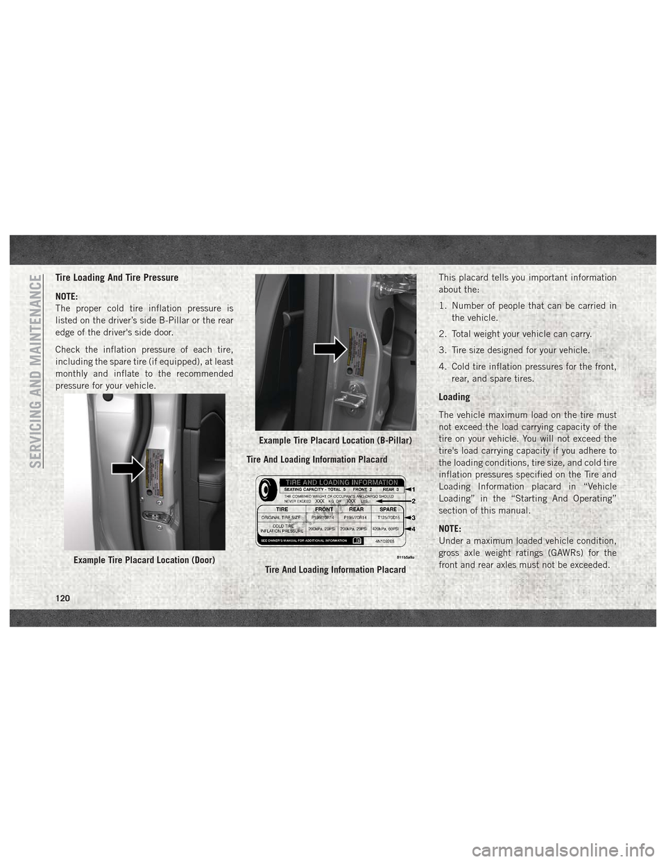
NOTE:
The proper cold tire inflation pressure is
listed on the driver’s side B-Pillar or the rear
edge of the driver's side door.
Check the inflation pressure of each tire,
including the spare tire (if equipped), at least
monthly and inflate to the recommended
pressure for your vehicle.Tire And Loading Information Placard This placard tells you important information
about the:
1. Number of people that can be carried in
the vehicle.
2. Total weight your vehicle can carry.
3. Tire size designed for your vehicle.
4. Cold tire inflation pressures for the front, rear, and spare tires.
Loading
The vehicle maximum load on the tire must
not exceed the load carrying capacity of the
tire on your vehicle. You will not exceed the
tire's load carrying capacity if you adhere to
the loading conditions, tire size, and cold tire
inflation pressures specified on the Tire and
Loading Information placard in “Vehicle
Loading” in the “Starting And Operating”
section of this manual.
NOTE:
Under a maximum loaded vehicle condition,
gross axle weight ratings (GAWRs) for the
front and rear axles must not be exceeded.
Example Tire Placard Location (Door)
Example Tire Placard Location (B-Pillar)
Tire And Loading Information Placard
SERVICING AND MAINTENANCE
120
Page 123 of 180
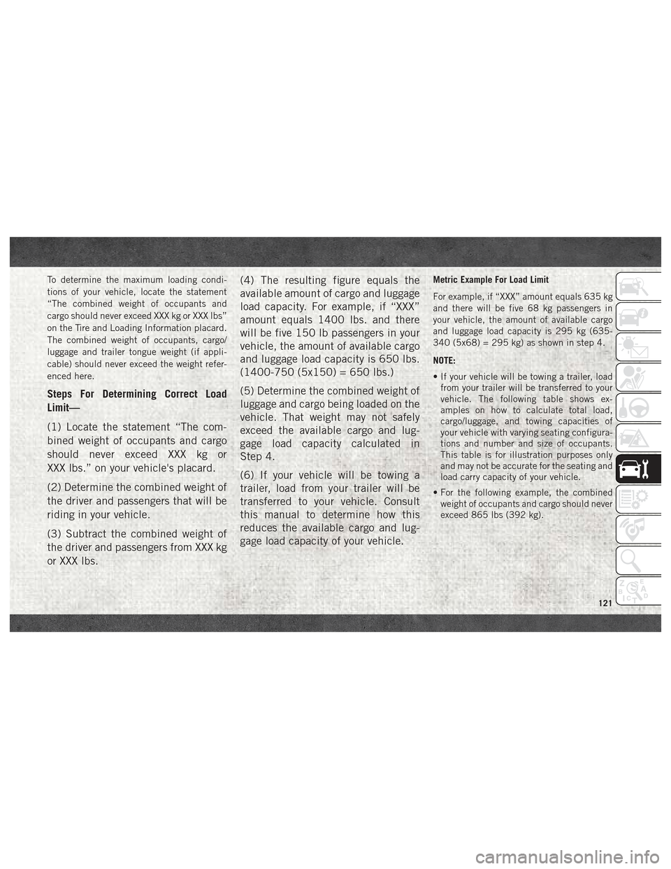
To determine the maximum loading condi-
tions of your vehicle, locate the statement
“The combined weight of occupants and
cargo should never exceed XXX kg or XXX lbs”
on the Tire and Loading Information placard.
The combined weight of occupants, cargo/
luggage and trailer tongue weight (if appli-
cable) should never exceed the weight refer-
enced here.
Steps For Determining Correct Load
Limit—
(1) Locate the statement “The com-
bined weight of occupants and cargo
should never exceed XXX kg or
XXX lbs.” on your vehicle's placard.
(2) Determine the combined weight of
the driver and passengers that will be
riding in your vehicle.
(3) Subtract the combined weight of
the driver and passengers from XXX kg
or XXX lbs.(4) The resulting figure equals the
available amount of cargo and luggage
load capacity. For example, if “XXX”
amount equals 1400 lbs. and there
will be five 150 lb passengers in your
vehicle, the amount of available cargo
and luggage load capacity is 650 lbs.
(1400-750 (5x150) = 650 lbs.)
(5) Determine the combined weight of
luggage and cargo being loaded on the
vehicle. That weight may not safely
exceed the available cargo and lug-
gage load capacity calculated in
Step 4.
(6) If your vehicle will be towing a
trailer, load from your trailer will be
transferred to your vehicle. Consult
this manual to determine how this
reduces the available cargo and lug-
gage load capacity of your vehicle.
Metric Example For Load Limit
For example, if “XXX” amount equals 635 kg
and there will be five 68 kg passengers in
your vehicle, the amount of available cargo
and luggage load capacity is 295 kg (635-
340 (5x68) = 295 kg) as shown in step 4.
NOTE:
• If your vehicle will be towing a trailer, load
from your trailer will be transferred to your
vehicle. The following table shows ex-
amples on how to calculate total load,
cargo/luggage, and towing capacities of
your vehicle with varying seating configura-
tions and number and size of occupants.
This table is for illustration purposes only
and may not be accurate for the seating and
load carry capacity of your vehicle.
• For the following example, the combined weight of occupants and cargo should never
exceed 865 lbs (392 kg).
121