start stop button RENAULT CAPTUR 2017 1.G User Guide
[x] Cancel search | Manufacturer: RENAULT, Model Year: 2017, Model line: CAPTUR, Model: RENAULT CAPTUR 2017 1.GPages: 248, PDF Size: 6.56 MB
Page 89 of 248
2.7
FUNCTION STOP AND START (2/4)
To fill up with fuel, the engine must
be stopped (and not on standby):
always stop the engine by pressing
the engine stop button (please see
“Starting, stopping the engine)”.
Preventing the engine from
standing by
In certain situations, such as negotiat-
ing a crossroads for instance, it is pos-
sible to keep the engine running so as
to be ready to move off quickly.
For vehicles equipped with auto-
matic gearboxes:
Keep the vehicle stationary without
pressing too hard on the brake pedal
For vehicles equipped with manual
gearboxes:
Keep the clutch pedal pressed right
down
Conditions for coming out of
engine standby
For vehicles equipped with auto-
matic gearboxes:
– the brake pedal is released, position D or M engaged or,
– the brake pedal is released, position N engaged and the handbrake off, or
– the brake pedal is pressed again, with position P engaged or position
N engaged with the handbrake ap-
plied, or
– position R is engaged or,
– the accelerator pedal is pressed.
For vehicles equipped with manual
gearboxes:
– the gearbox is in neutral and the clutch pedal is slightly depressed, or
– the engine is in gear and the clutch pedal is pressed right down. Special note:
depending on the vehi-
cle, if you switch off the ignition when
the engine is on standby, the warning
light Ä is displayed for a few sec-
onds on the instrument panel.
Page 90 of 248
2.8
FUNCTION STOP AND START (3/4)
Conditions preventing the
standby of the engine
Certain conditions prevent the system
from using the engine standby function,
including when:
– reverse gear is engaged;
– the bonnet is not locked;
– the driver’s door is not closed;
– the driver’s seatbelt is not fastened;
– the outdoor temperature is too low or too high (less than around 0 °C or
higher than around 30 °C);
– the battery is not sufficiently charged;
– the difference between the vehicle interior temperature and the auto-
matic climate control instruction is
too high; – for vehicles with automatic gear-
boxes, the gradient is steeper than
approximately 12%;
– the “Clear View” function is activated (please see “Automatic Climate
Control” in Section 3);
– the engine temperature is too low;
– the emission control system is being regenerated;
or
– ...
The warning light
or, depend-
ing on the vehicle, the message “AUTO
STOP UNAVAILABLE” appears on the
instrument panel indicating that engine
standby is not available.
Deactivate the Stop and
Start function when per-
forming any operations in
the engine compartment.
Special cases
With the engine on standby (traffic jam,
traffic lights, etc.), if the driver unfastens
their seat belt, opens the driver’s door
or gets out of their seat, the ignition will
be switched off.
To restart and reactivate the Stop and
Start system, press the start button
(please see “Starting, stopping the
engine” in Section 2).
Page 91 of 248
2.9
Special feature of the automatic
engine re-start
Under certain conditions, the engine
can restart on its own in order to guar-
antee your safety and comfort.
This can occur especially when:
– the outdoor temperature is too low or too high (less than around 0 °C or
higher than around 30 °C);
– the “Clear View” function is activated (please see “Automatic Climate
Control” in Section 3);
– the battery is not sufficiently charged;
– the vehicle speed is above 3 mph (5 km/h) (downhill slope, etc.);
– repeated pressing on the brake pedal or braking system require-
ment;
– ...
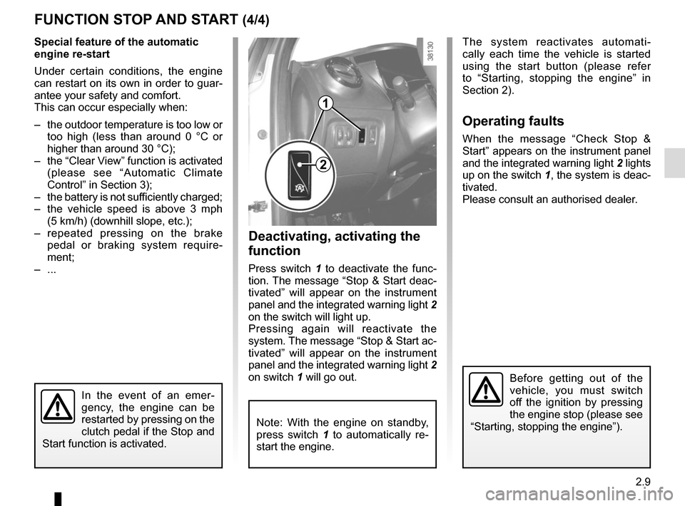
Deactivating, activating the
function
Press switch 1 to deactivate the func-
tion. The message “Stop & Start deac-
tivated” will appear on the instrument
panel and the integrated warning light 2
on the switch will light up.
Pressing again will reactivate the
system. The message “Stop & Start ac-
tivated” will appear on the instrument
panel and the integrated warning light 2
on switch 1 will go out.
FUNCTION STOP AND START (4/4)
The system reactivates automati-
cally each time the vehicle is started
using the start button (please refer
to “Starting, stopping the engine” in
Section 2).
Operating faults
When the message “Check Stop &
Start” appears on the instrument panel
and the integrated warning light 2 lights
up on the switch 1, the system is deac-
tivated.
Please consult an authorised dealer.
1
2
Before getting out of the
vehicle, you must switch
off the ignition by pressing
the engine stop (please see
“Starting, stopping the engine”).
In the event of an emer-
gency, the engine can be
restarted by pressing on the
clutch pedal if the Stop and
Start function is activated.
Note: With the engine on standby,
press switch 1 to automatically re-
start the engine.
Page 107 of 248
2.25
TYRE PRESSURE LOSS WARNING (6/7)
2
3
4
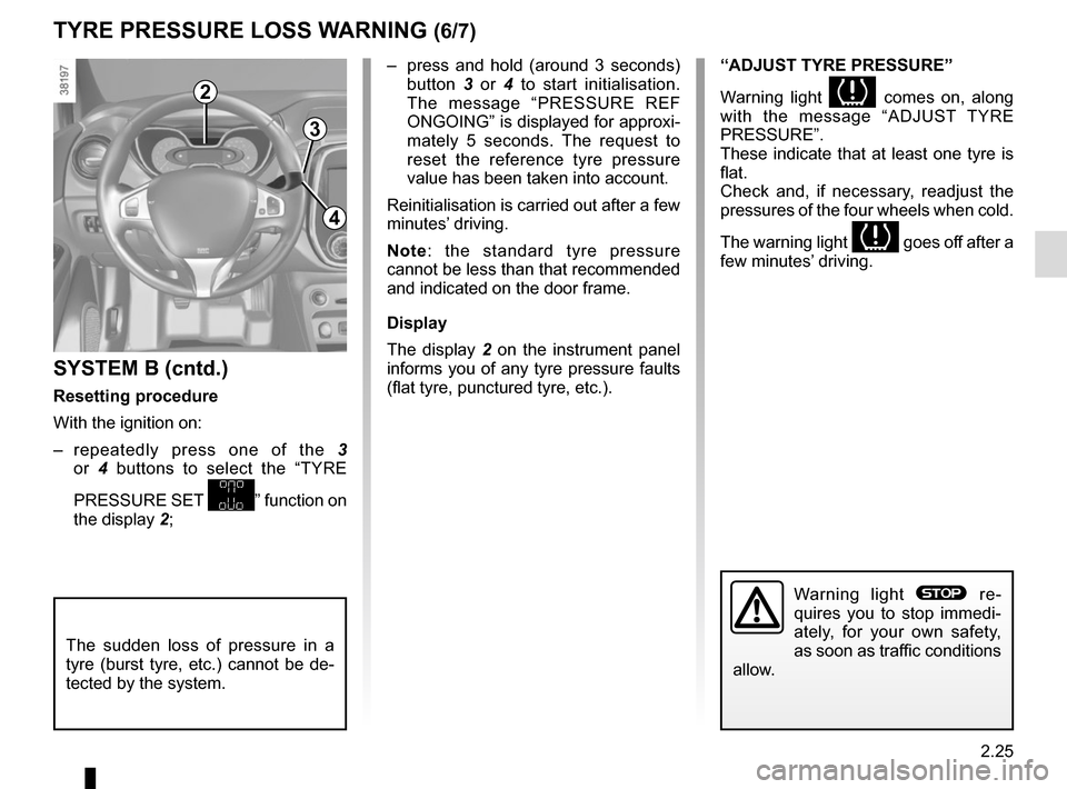
– press and hold (around 3 seconds) button 3 or 4 to start initialisation.
The message “PRESSURE REF
ONGOING” is displayed for approxi-
mately 5 seconds. The request to
reset the reference tyre pressure
value has been taken into account.
Reinitialisation is carried out after a few
minutes’ driving.
Note: the standard tyre pressure
cannot be less than that recommended
and indicated on the door frame.
Display
The display 2 on the instrument panel
informs you of any tyre pressure faults
(flat tyre, punctured tyre, etc.).
SYSTEM B (cntd.)
Resetting procedure
With the ignition on:
– repeatedly press one of the 3
or 4 buttons to select the “TYRE
PRESSURE SET
” function on
the display 2;
“ADJUST TYRE PRESSURE”
Warning light
comes on, along
with the message “ADJUST TYRE
PRESSURE”.
These indicate that at least one tyre is
flat.
Check and, if necessary, readjust the
pressures of the four wheels when cold.
The warning light
goes off after a
few minutes’ driving.
The sudden loss of pressure in a
tyre (burst tyre, etc.) cannot be de-
tected by the system.
Warning light ® re-
quires you to stop immedi-
ately, for your own safety,
as soon as traffic conditions
allow.
Page 135 of 248
3.7
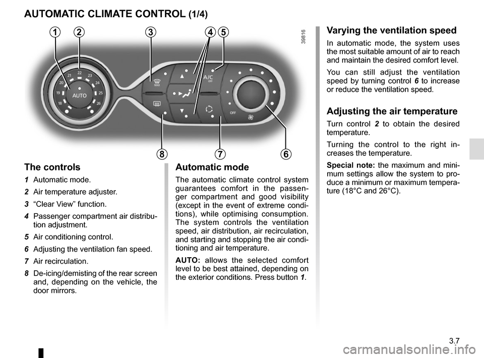
Varying the ventilation speed
In automatic mode, the system uses
the most suitable amount of air to reach
and maintain the desired comfort level.
You can still adjust the ventilation
speed by turning control 6 to increase
or reduce the ventilation speed.
Adjusting the air temperature
Turn control 2 to obtain the desired
temperature.
Turning the control to the right in-
creases the temperature.
Special note: the maximum and mini-
mum settings allow the system to pro-
duce a minimum or maximum tempera-
ture (18°C and 26°C).
The controls
1 Automatic mode.
2 Air temperature adjuster.
3 “Clear View” function.
4 Passenger compartment air distribu-
tion adjustment.
5 Air conditioning control.
6 Adjusting the ventilation fan speed.
7 Air recirculation.
8 De-icing/demisting of the rear screen
and, depending on the vehicle, the
door mirrors.
AUTOMATIC CLIMATE CONTROL (1/4)
235
786
Automatic mode
The automatic climate control system
guarantees comfort in the passen-
ger compartment and good visibility
(except in the event of extreme condi-
tions), while optimising consumption.
The system controls the ventilation
speed, air distribution, air recirculation,
and starting and stopping the air condi-
tioning and air temperature.
AUTO: allows the selected comfort
level to be best attained, depending on
the exterior conditions. Press button 1.
14
Page 138 of 248

3.10
AUTOMATIC CLIMATE CONTROL (4/4)
76
Air recirculation (isolation of
the passenger compartment)
K
This function is managed automatically
(operation is confirmed by a warning
light on button 7), but you can also acti-
vate it manually.
NB:
– during recirculation, air is taken from the passenger compartment and
is recycled, with no air being taken
from outside the vehicle;
– air recirculation allows the external atmosphere to be cut off (when driv-
ing in polluted areas, etc.);
– the recirculation of air makes it pos- sible to reach the desired passenger
compartment temperature quicker.
1
The demisting/de-icing will still take
priority over the air recirculation.
Manual use
Press button 7 – the integrated indica-
tor light comes on.
Prolonged use of this position may lead
to odours, caused by non-renewal of
air, and the formation of condensation
on the windows.
We therefore advise you to return to au-
tomatic mode as soon as air recircula-
tion is no longer needed, by pressing
button 7.
To exit this function, press button 7
again. Stopping the system
Turn the control 6 to “OFF” to stop the
system. To start it, turn the control
6
again, then adjust the fan speed or
press the button 1.
Page 162 of 248
4.2
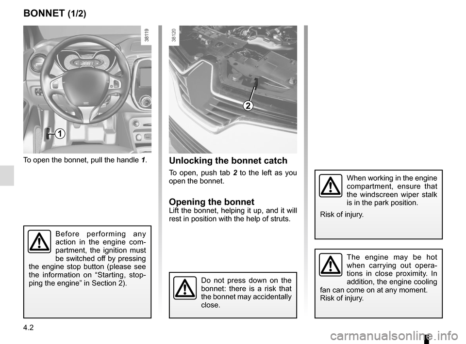
To open the bonnet, pull the handle 1.
BONNET (1/2)
1
The engine may be hot
when carrying out opera-
tions in close proximity. In
addition, the engine cooling
fan can come on at any moment.
Risk of injury.
Unlocking the bonnet catch
To open, push tab 2 to the left as you
open the bonnet.
Opening the bonnetLift the bonnet, helping it up, and it will
rest in position with the help of struts.
2
Do not press down on the
bonnet: there is a risk that
the bonnet may accidentally
close.
When working in the engine
compartment, ensure that
the windscreen wiper stalk
is in the park position.
Risk of injury.
Before performing any
action in the engine com-
partment, the ignition must
be switched off by pressing
the engine stop button (please see
the information on “Starting, stop-
ping the engine” in Section 2).
Page 164 of 248
4.4
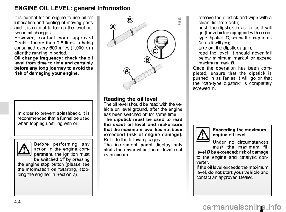
– remove the dipstick and wipe with a clean, lint-free cloth;
– push the dipstick in as far as it will go (for vehicles equipped with a cap-
type dipstick C, screw the cap in as
far as it will go);
– take out the dipstick again;
– read the level: it should never fall below minimum mark A or exceed
maximum mark B.
Once the operation has been com-
pleted, ensure that the dipstick is
pushed in as far as it will go or that
the “cap-type dipstick” is completely
screwed in.
Reading the oil levelThe oil level should be read with the ve-
hicle on level ground, after the engine
has been switched off for some time.
The dipstick must be used to read
the exact oil level and make sure
that the maximum level has not been
exceeded (risk of engine damage).
Refer to the following pages.
The instrument panel display only
alerts the driver when the oil level is at
its minimum.
It is normal for an engine to use oil for
lubrication and cooling of moving parts
and it is normal to top up the level be-
tween oil changes.
However, contact your approved
Dealer if more than 0.5 litres is being
consumed every 600 miles (1,000 km)
after the running in period.
Oil change frequency: check the oil
level from time to time and certainly
before any long journey to avoid the
risk of damaging your engine.
ENGINE OIL LEVEL: general information
A
B
A
B
C
In order to prevent splashback, it is
recommended that a funnel be used
when topping up/filling with oil.
Before performing any
action in the engine com-
partment, the ignition must
be switched off by pressing
the engine stop button (please see
the information on “Starting, stop-
ping the engine” in Section 2).
Exceeding the maximum
engine oil level
Under no circumstances
must the maximum fill
level B be exceeded: risk of damage
to the engine and catalytic con-
verter.
If the oil level exceeds the maximum
level, do not start your vehicle and
contact an approved Dealer.
Page 165 of 248
4.5
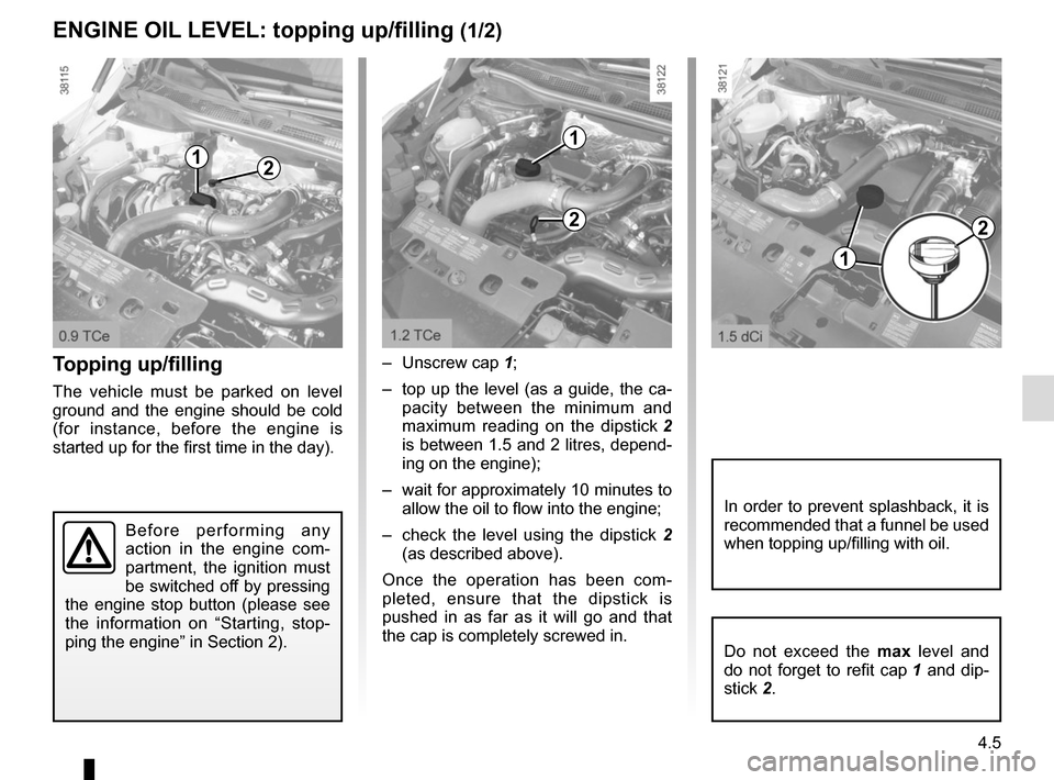
Topping up/filling
The vehicle must be parked on level
ground and the engine should be cold
(for instance, before the engine is
started up for the first time in the day).– Unscrew cap
1;
– top up the level (as a guide, the ca- pacity between the minimum and
maximum reading on the dipstick 2
is between 1.5 and 2 litres, depend-
ing on the engine);
– wait for approximately 10 minutes to allow the oil to flow into the engine;
– check the level using the dipstick 2
(as described above).
Once the operation has been com-
pleted, ensure that the dipstick is
pushed in as far as it will go and that
the cap is completely screwed in.
ENGINE OIL LEVEL: topping up/filling (1/2)
12
Do not exceed the max level and
do not forget to refit cap 1 and dip-
stick 2.
In order to prevent splashback, it is
recommended that a funnel be used
when topping up/filling with oil.
2
1
1
2
Before performing any
action in the engine com-
partment, the ignition must
be switched off by pressing
the engine stop button (please see
the information on “Starting, stop-
ping the engine” in Section 2).
Page 167 of 248
4.7
Frequency of checking coolant level
Check the coolant level regularly
(very severe damage is likely to be
caused to the engine if it runs out of
coolant).
If the level needs to be topped up, only
use products approved by our Technical
Department which ensure:
– protection against freezing;
– an anti-corrosion protection for the cooling system.
Consult your approved dealer at
once if you notice an abnormal or
repeated drop in any of the fluid
levels.
No operations should be
carried out on the cooling
circuit when the engine is
hot.
Risk of burns.
Replacement interval
Refer to the Maintenance Document for
your vehicle.
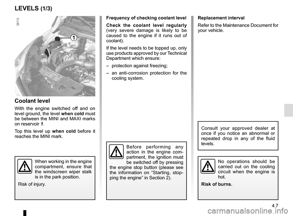
Coolant level
With the engine switched off and on
level ground, the level when cold must
be between the MINI and MAXI marks
on reservoir 1.
Top this level up when cold before it
reaches the MINI mark.
LEVELS (1/3)
1
When working in the engine
compartment, ensure that
the windscreen wiper stalk
is in the park position.
Risk of injury.
Before performing any
action in the engine com-
partment, the ignition must
be switched off by pressing
the engine stop button (please see
the information on “Starting, stop-
ping the engine” in Section 2).