replace RENAULT CAPTUR 2017 1.G Owner's Manual
[x] Cancel search | Manufacturer: RENAULT, Model Year: 2017, Model line: CAPTUR, Model: RENAULT CAPTUR 2017 1.GPages: 248, PDF Size: 6.56 MB
Page 124 of 248
2.42
REVERSING CAMERA (2/2)
The screen shows a reverse image.
The frames are a representation
projected onto flat ground; this in-
formation must not be taken into
account when superimposed on a
vertical object or an object on the
ground.
Objects which appear on the edge
of the screen may be deformed.
In very bright light (snow, vehicle in
sunshine etc.), the camera vision
may be adversely affected.
If the boot is open or poorly closed,
the message “Boot open
2” ap-
pears and, depending on the vehi-
cle, the camera display disappears.
This function is an additional
aid. It cannot, therefore,
under any circumstances
replace the vigilance or the
responsibility of the driver.
The driver should always pay atten-
tion to sudden incidents during driv-
ing: always ensure that there are no
moving obstacles (such as a child,
animal, pram, bicycle, etc.) or small,
narrow objects such as stones or
posts in your path when manoeu-
vring.
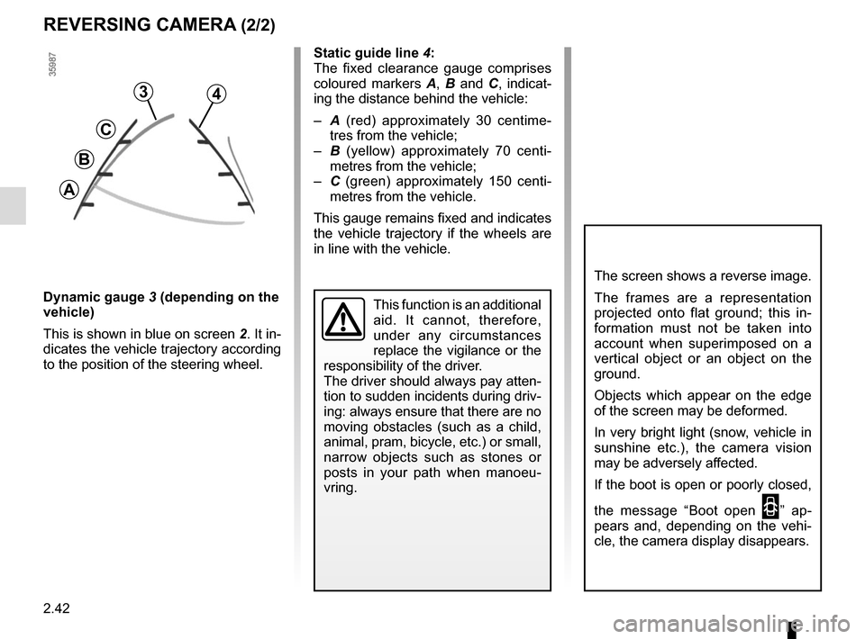
3
C
B
A
4
Static guide line 4:
The fixed clearance gauge comprises
coloured markers A, B and C , indicat-
ing the distance behind the vehicle:
– A (red) approximately 30 centime-
tres from the vehicle;
– B (yellow) approximately 70 centi-
metres from the vehicle;
– C (green) approximately 150 centi-
metres from the vehicle.
This gauge remains fixed and indicates
the vehicle trajectory if the wheels are
in line with the vehicle.
Dynamic gauge 3 (depending on the
vehicle)
This is shown in blue on screen 2. It in-
dicates the vehicle trajectory according
to the position of the steering wheel.
Page 148 of 248
3.20
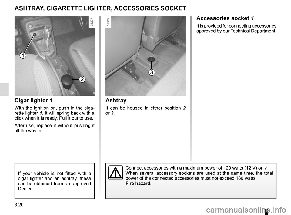
Cigar lighter 1
With the ignition on, push in the ciga-
rette lighter 1. It will spring back with a
click when it is ready. Pull it out to use.
After use, replace it without pushing it
all the way in.
ASHTRAY, CIGARETTE LIGHTER, ACCESSORIES SOCKET
3
Connect accessories with a maximum power of 120 watts (12 V) only.
When several accessory sockets are used at the same time, the total
power of the connected accessories must not exceed 180 watts.
Fire hazard.
If your vehicle is not fitted with a
cigar lighter and an ashtray, these
can be obtained from an approved
Dealer.
Accessories socket 1
It is provided for connecting accessories
approved by our Technical Department.
2
1
Ashtray
It can be housed in either position 2
or 3.
Page 151 of 248
3.23
B
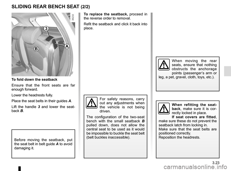
To fold down the seatback
Ensure that the front seats are far
enough forward.
Lower the headrests fully.
Place the seat belts in their guides A.
Lift the handle 3 and lower the seat-
back B.
Before moving the seatback, put
the seat belt in belt guide A to avoid
damaging it.
To replace the seatback, proceed in
the reverse order to removal.
Refit the seatback and click it back into
place.
For safety reasons, carry
out any adjustments when
the vehicle is not being
driven.
The configuration of the two-seat
bench with the small seatback B
pulled down, does not allow the
central seat to be used as it would
be impossible to buckle the seat belt
(belt buckles inaccessible).
When moving the rear
seats, ensure that nothing
obstructs the anchorage
points (passenger’s arm or
leg, a pet, gravel, cloth, toys, etc.).
When refitting the seat-
back, make sure it is cor-
rectly locked in place.
If seat covers are fitted ,
make sure these do not prevent the
seatback latch from locking in.
Make sure that the seat belts are
positioned correctly.
Reposition the headrests.
SLIDING REAR BENCH SEAT (2/2)
A
3
Page 167 of 248
4.7
Frequency of checking coolant level
Check the coolant level regularly
(very severe damage is likely to be
caused to the engine if it runs out of
coolant).
If the level needs to be topped up, only
use products approved by our Technical
Department which ensure:
– protection against freezing;
– an anti-corrosion protection for the cooling system.
Consult your approved dealer at
once if you notice an abnormal or
repeated drop in any of the fluid
levels.
No operations should be
carried out on the cooling
circuit when the engine is
hot.
Risk of burns.
Replacement interval
Refer to the Maintenance Document for
your vehicle.
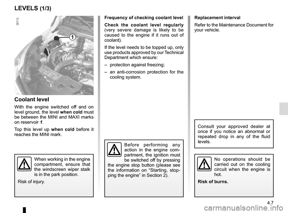
Coolant level
With the engine switched off and on
level ground, the level when cold must
be between the MINI and MAXI marks
on reservoir 1.
Top this level up when cold before it
reaches the MINI mark.
LEVELS (1/3)
1
When working in the engine
compartment, ensure that
the windscreen wiper stalk
is in the park position.
Risk of injury.
Before performing any
action in the engine com-
partment, the ignition must
be switched off by pressing
the engine stop button (please see
the information on “Starting, stop-
ping the engine” in Section 2).
Page 168 of 248
4.8
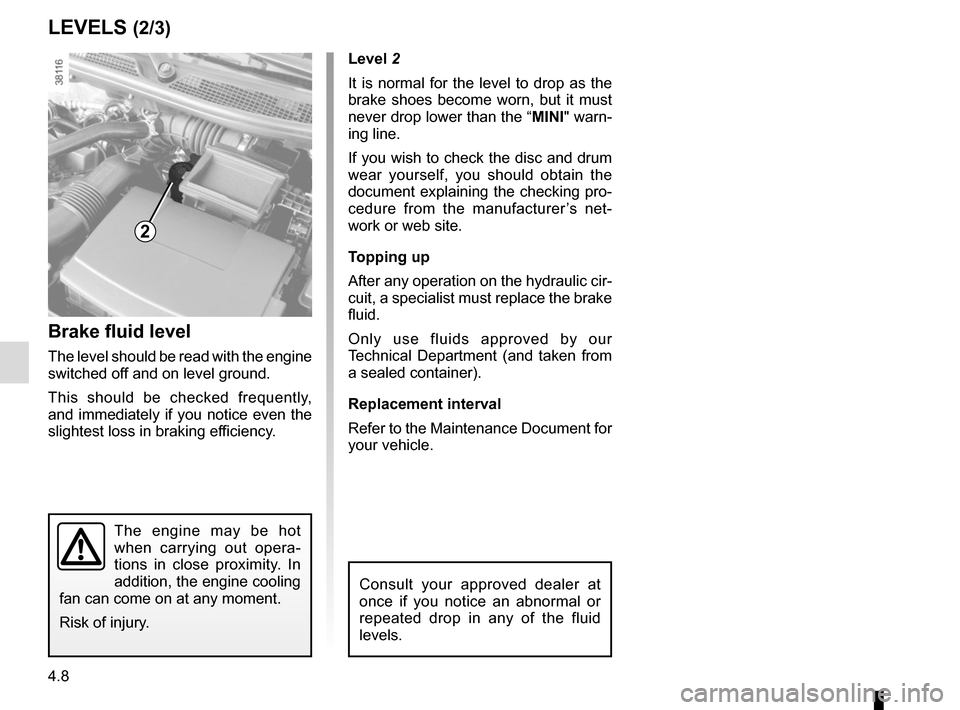
Level 2
It is normal for the level to drop as the
brake shoes become worn, but it must
never drop lower than the “MINI" warn-
ing line.
If you wish to check the disc and drum
wear yourself, you should obtain the
document explaining the checking pro-
cedure from the manufacturer’s net-
work or web site.
Topping up
After any operation on the hydraulic cir-
cuit, a specialist must replace the brake
fluid.
Only use fluids approved by our
Technical Department (and taken from
a sealed container).
Replacement interval
Refer to the Maintenance Document for
your vehicle.
Brake fluid level
The level should be read with the engine
switched off and on level ground.
This should be checked frequently,
and immediately if you notice even the
slightest loss in braking efficiency.
LEVELS (2/3)
2
The engine may be hot
when carrying out opera-
tions in close proximity. In
addition, the engine cooling
fan can come on at any moment.
Risk of injury.
Consult your approved dealer at
once if you notice an abnormal or
repeated drop in any of the fluid
levels.
Page 169 of 248
4.9
Filters
The replacement of filter components
(air filter, cabin filter, diesel filter, etc.)
is scheduled in the maintenance opera-
tions for your vehicle.
Replacement intervals for filter el-
ements: refer to the Maintenance
Document for your vehicle.
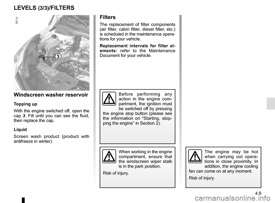
Windscreen washer reservoir
Topping up
With the engine switched off, open the
cap 3. Fill until you can see the fluid,
then replace the cap.
Liquid
Screen wash product (product with
antifreeze in winter).
LEVELS (3/3)/FILTERS
3
When working in the engine
compartment, ensure that
the windscreen wiper stalk
is in the park position.
Risk of injury.The engine may be hot
when carrying out opera-
tions in close proximity. In
addition, the engine cooling
fan can come on at any moment.
Risk of injury.
Before performing any
action in the engine com-
partment, the ignition must
be switched off by pressing
the engine stop button (please see
the information on “Starting, stop-
ping the engine” in Section 2).
Page 172 of 248
4.12
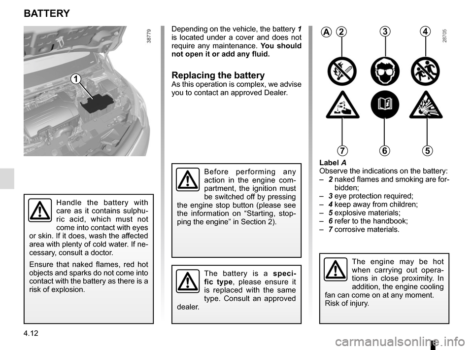
Label A
Observe the indications on the battery:
– 2 naked flames and smoking are for-
bidden;
– 3 eye protection required;
– 4 keep away from children;
– 5 explosive materials;
– 6 refer to the handbook;
– 7 corrosive materials.
BATTERY
1
2
Handle the battery with
care as it contains sulphu-
ric acid, which must not
come into contact with eyes
or skin. If it does, wash the affected
area with plenty of cold water. If ne-
cessary, consult a doctor.
Ensure that naked flames, red hot
objects and sparks do not come into
contact with the battery as there is a
risk of explosion.
The battery is a speci-
fic type, please ensure it
is replaced with the same
type. Consult an approved
dealer.
A234
567
The engine may be hot
when carrying out opera-
tions in close proximity. In
addition, the engine cooling
fan can come on at any moment.
Risk of injury.
Depending on the vehicle, the battery 1
is located under a cover and does not
require any maintenance. You should
not open it or add any fluid.
Replacing the battery
As this operation is complex, we advise
you to contact an approved Dealer.
Before performing any
action in the engine com-
partment, the ignition must
be switched off by pressing
the engine stop button (please see
the information on “Starting, stop-
ping the engine” in Section 2).
Page 184 of 248
5.2
In case of punctureDepending on the vehicle, a tyre infla-
tion kit or emergency spare wheel is
provided (refer to the following pages).
Vehicle fitted with a tyre pressure
loss warning system
If under-inflated (puncture, low pres-
sure etc.), the warning light
on
the instrument panel comes on. See
“Tyre pressure loss warning” in
Section 2.
If the emergency spare wheel has been stored for several years, have it \
checked by your Dealer to ensure that it is safe to use.
Vehicle fitted with an emergency spare wheel that differs from the
other wheels:
– Never fit more than one emergency spare wheel to the same vehicle.
– Replace the emergency spare wheel as soon as possible with a wheel ident\
i- cal to the original one.
– When this is fitted to the vehicle, which must only be a temporary measu\
re, the driving speed must not exceed the speed indicated on the label on the wh\
eel.
– Fitting an emergency spare wheel may alter the way the vehicle usually r\
uns. Avoid sudden acceleration or deceleration and reduce your speed when cor-\
nering.
– If you need to use snow chains, fit the emergency spare wheel to the rea\
r axle and check the tyre pressure.
– The warning light
on the instrument panel flashes for several seconds,
then stays on.
PUNCTURE, EMERGENCY SPARE WHEEL (1/2)
If the vehicle is parked on
the hard shoulder, you must
warn other road users of
your vehicle’s presence
with a warning triangle or with other
devices as per the legislation apply-
ing to the country you are in.
Page 186 of 248
5.4
TYRE PRESSURE KIT (1/3)
The kit is only approved for
inflating the tyres of the ve-
hicle originally equipped
with the kit.
It must never be used to inflate
the tyres of another vehicle, or any
other inflatable object (rubber ring,
rubber boat, etc.).
Avoid spillage on skin when hand-
ling the repair liquid bottle. If drop-
lets do leak out, rinse them off with
plenty of water.
Keep the repair kit away from chil-
dren.
Do not dispose of the empty bottle
in the countryside. Return it to your
approved dealer or to a recycling or-
ganisation.
The bottle has a limited service
life which is indicated on its label.
Check the expiry date.
Contact an approved dealer to re-
place the inflation tube and repair
product bottle.
A
B
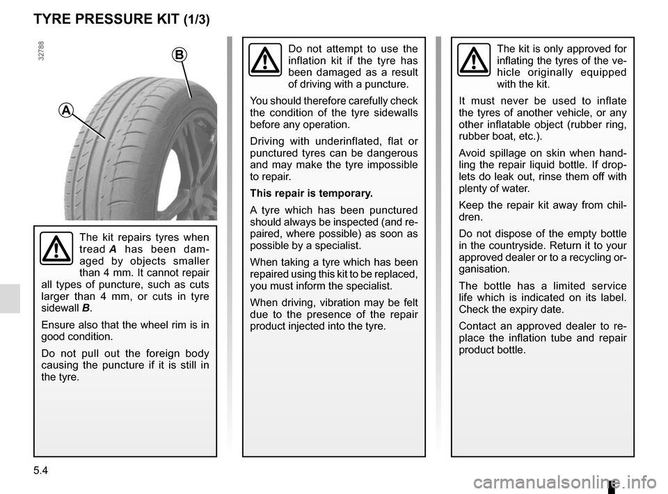
The kit repairs tyres when
tread A has been dam-
aged by objects smaller
than 4 mm. It cannot repair
all types of puncture, such as cuts
larger than 4 mm, or cuts in tyre
sidewall B.
Ensure also that the wheel rim is in
good condition.
Do not pull out the foreign body
causing the puncture if it is still in
the tyre.
Do not attempt to use the
inflation kit if the tyre has
been damaged as a result
of driving with a puncture.
You should therefore carefully check
the condition of the tyre sidewalls
before any operation.
Driving with underinflated, flat or
punctured tyres can be dangerous
and may make the tyre impossible
to repair.
This repair is temporary.
A tyre which has been punctured
should always be inspected (and re-
paired, where possible) as soon as
possible by a specialist.
When taking a tyre which has been
repaired using this kit to be replaced,
you must inform the specialist.
When driving, vibration may be felt
due to the presence of the repair
product injected into the tyre.
Page 188 of 248
5.6
TYRE PRESSURE KIT (3/3)
If a minimum pressure of 1.8 bar is
not reached after 15 minutes, repair
is not possible; do not drive the ve-
hicle but contact an approved dealer.
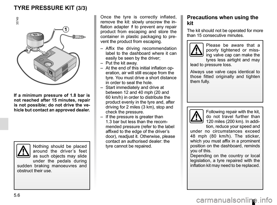
Once the tyre is correctly inflated,
remove the kit: slowly unscrew the in-
flation adapter 1 to prevent any repair
product from escaping and store the
container in plastic packaging to pre-
vent the product from escaping.
– Affix the driving recommendation label to the dashboard where it can
easily be seen by the driver;
– Put the kit away.
– At the end of this initial inflation op- eration, air will still escape from the
tyre. You must drive a short distance
in order to seal the hole.
– Start immediately and drive at between 12 and 40 mph (20 and
60 km/h) in order to distribute the
product evenly in the tyre and, after
driving for 2 miles (3 km), stop and
check the pressure.
– If the pressure is greater than 1.3 bar but less than the recom-
mended pressure (refer to the label
affixed to the edge of the driver’s
door), readjust it. Otherwise, please
contact an authorised dealer: the
tyre cannot be repaired.Precautions when using the
kit
The kit should not be operated for more
than 15 consecutive minutes.
Nothing should be placed
around the driver’s feet
as such objects may slide
under the pedals during
sudden braking manoeuvres and
obstruct their use.
1
Please be aware that a
poorly tightened or miss-
ing valve cap can make the
tyres less airtight and may
lead to pressure loss.
Always use valve caps identical to
those fitted originally and tighten
them fully.
Following repair with the kit,
do not travel further than
120 miles (200 km). In addi-
tion, reduce your speed and
under no circumstances exceed
48 mph (80 km/h). The sticker,
which you must affix in a prominent
position on the dashboard, reminds
you of this.
Depending on the country or local
legislation, a tyre repaired with the
inflation kit may need to be replaced.