check engine light RENAULT CLIO CUP 2013 X85 / 3.G User Manual
[x] Cancel search | Manufacturer: RENAULT, Model Year: 2013, Model line: CLIO CUP, Model: RENAULT CLIO CUP 2013 X85 / 3.GPages: 35, PDF Size: 2.68 MB
Page 30 of 35

Downloaded from www.Manualslib.com manuals search engine 98CUP_2013 Release
C-30
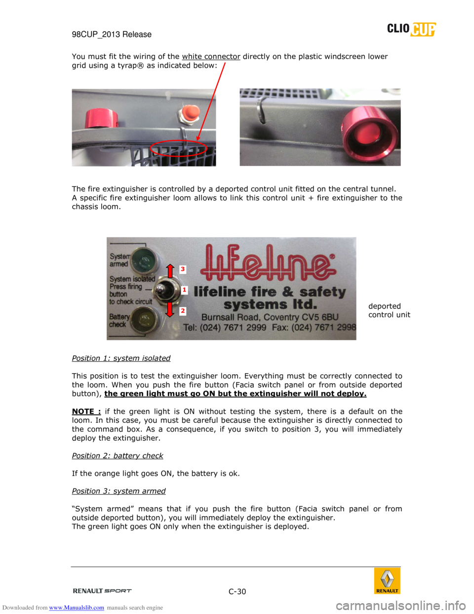
You must fit the wiring of the white connector directly on the plastic windscreen lower
grid using a tyrap® as indicated below:
The fire extinguisher is controlled by a deported c ontrol unit fitted on the central tunnel.
A specific fire extinguisher loom allows to link th is control unit + fire extinguisher to the
chassis loom.
Position 1: system isolated
This position is to test the extinguisher loom. Eve rything must be correctly connected to
the loom. When you push the fire button (Facia swit ch panel or from outside deported
button), the green light must go ON but the extinguisher will n ot deploy.
NOTE :
if the green light is ON without testing the syste m, there is a default on the
loom. In this case, you must be careful because the extinguisher is directly connected to
the command box. As a consequence, if you switch to position 3, you will immediately
deploy the extinguisher.
Position 2: battery check
If the orange light goes ON, the battery is ok.
Position 3: system armed
“System armed” means that if you push the fire butt on (Facia switch panel or from
outside deported button), you will immediately depl oy the extinguisher.
The green light goes ON only when the extinguisher is deployed.
3
1
2 deported
control unit
Page 31 of 35

Downloaded from www.Manualslib.com manuals search engine 98CUP_2013 Release
C-31
Checks
-
Extinguisher cylinder compliance check:
The following information must be clearly
visible on the cylinder: · Serial number.
· Capacity and weight or volume of
extinguisher product.
· Activation date or date of last system check.
· Date of next service.
· Homologation number.
Take care not to exceed the extinguisher’s
next scheduled service date.
- Pressure check
The pressure of the cylinder may be checked using a
manometer placed on the cylinder.
The needle must be situated in the green area on th e
manometer dial.
B.7.2 CIRCUIT BREAKER
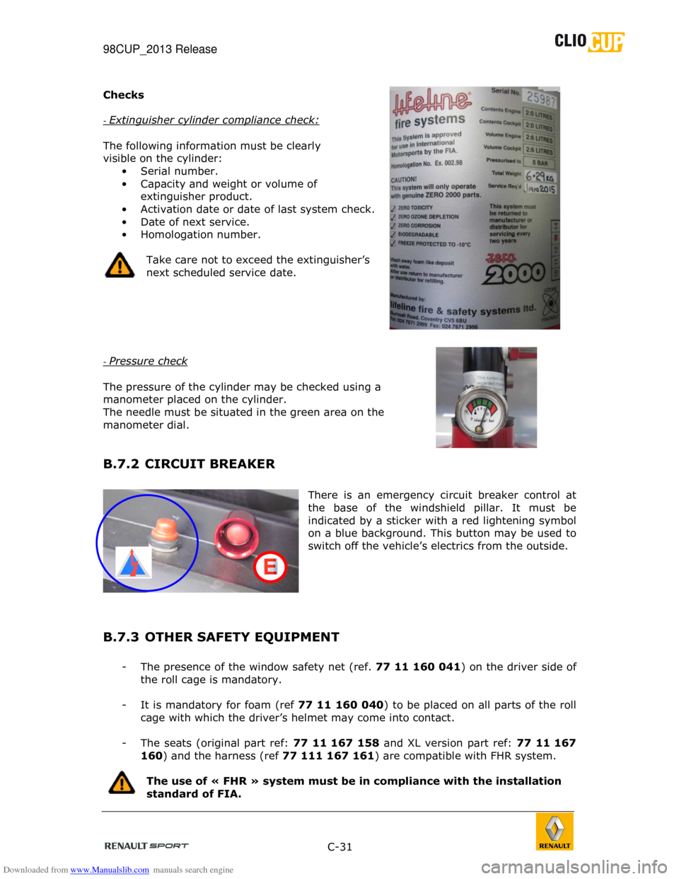
There is an emergency circuit breaker control at
the base of the windshield pillar. It must be
indicated by a sticker with a red lightening symbol
on a blue background. This button may be used to
switch off the vehicle’s electrics from the outside .
B.7.3 OTHER SAFETY EQUIPMENT
- The presence of the window safety net (ref. 77 11 160 041) on the driver side of
the roll cage is mandatory.
- It is mandatory for foam (ref 77 11 160 040) to be placed on all parts of the roll
cage with which the driver’s helmet may come into c ontact.
- The seats (original part ref: 77 11 167 158 and XL version part ref: 77 11 167
160 ) and the harness (ref 77 111 167 161) are compatible with FHR system.
The use of « FHR » system must be in compliance with the installation
standard of FIA.